1
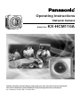
Operating Instructions
Network Camera
Model No.
KX-HCM110A
Please read this manual before using and save this manual for future reference.
Panasonic Network Camera Website: http://www.panasonic.com/netcam
for customers in the USA or Puerto Rico
Operating Instructions
Main Features
IPv6*1 Network Camera
Your Panasonic Network Camera supports IPv6 (Internet Protocol Version 6), IPv6
was created to address the additional IP addresses that will be needed as the
Internet continues to expand. Since the camera also supports IPv4 that's currently
used, it is "dual stack" design will seamlessly operate while IPv6 is phased in. For
more information in IPv6 you wish to visit http://www.ipv6.org/. See page 15 for
more information.
Audio 2-way Communication*2 (Walkie-talkie Type)
Your Panasonic Network Camera now provides 2-way audio, between the camera
and your PC. You will be able to hear the person on camera and respond using a
microphone connected to your PC's sound card (customer-provided.) They will
hear your response through the amplified speaker (customer-provided) connected
to the camera.
For example, the camera can be used in the following various locations:
•
In the baby's room, to hear if the baby is crying.
•
At the front door, to see and hear who is at the door.
•
In the children's play room, to see and hear if they are safe.
Note
PLEASE NOTE that under certain circumstances, audio/video recording may
be PROHIBITED by law. This device should be used only in compliance with
all applicable federal, state and local statutes.
Digital zoom feature*3
Camera has a 10x digital zoom feature.
This feature allows you to increase or decrease the size of the object on the Single
Camera screen, the Multi Camera screen, and the Buffered Image screen.
Therefore, it will be easy to view the object that located to a distant place.*4 A mouse
wheel operation and clicking the right mouse button increase or decrease the size
of the object on the Single Camera screen.
*1
*2
*3
*4
2
To connect in IPv6, subscribe to the ISP's "IPv4/IPv6 Dual-Stack" or "IPv6 over IPv4
Tunneling" service. The camera does not work in IPv6-only network.
Audio feature does not work on cell phones. Talk button and Listen button cannot be used
simultaneously. In consequence of traffic and network environments, the audio may be
delayed or may break up.
This feature is not available when viewing on a cell phone.
As the magnification increases, the image quality decreases.
Operating Instructions
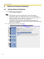
Various Camera Control Features
The camera pans or tilts fast in maximum 80 ° per second. You can control the
camera at high speed from your PC or cell phone. Alarm position feature also
allows the camera to automatically turn the lens to the alarm position. Additionally,
the following control features are available to easily and quickly monitor the
camera.
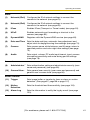
Click to Center ......... When you click a certain point on the camera image, the
point is centered on the image.
Preset Position ......... You can register 8 preset positions. When you click each
button, the image switches to its position.
Output Control ......... You can control the external devices (Open or Short to
GND) (E.g., turning the light on or ringing a buzzer).
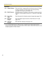
Multi-Camera Support
Multi-Camera page displays up to 4 cameras while supporting each audio 2-way
communication. The previous model displays only 4 cameras, but this camera can
switch 3 sets of 4 cameras. Additionally, the camera can displays maximum 12
cameras on a page in a static image.
DynamicDNS Service Support
DynamicDNS service allows you to access the camera over the Internet with your
favorite domain name (e.g. bob.viewnetcam.com) instead of a global IP address.
Multi-Language Display
Top page, Single Camera and Multi-Camera page can be displayed in English,
French, German, Italian, Spanish, Russian, Simplified Chinese or Japanese. The
Setup, Maintenance and Support pages are displayed only in English or Japanese.
Motion Detection feature
Camera has a Motion Detection feature that detects movement, such as people,
based on the preset threshold and sensitivity of Camera.
You can buffer the camera images, transfer to an FTP server or send E-mails using
the Motion Detection function as a trigger.
[For assistance, please call: 1-800-272-7033]
3
Operating Instructions
How to Use This Documentation
The camera includes the following 4 manual types.
•
Installation
Installation provides explanations for items included with the camera.
•
Getting Started
Getting Started provides explanations for the initial configuration and the ways
of camera mount. The Getting Started helps you to easily configure the
camera.
•
Operating Instructions (This manual)
Operating Instructions explains about operations, settings, features and the
cleaning method when using the camera.
•
Troubleshooting
Troubleshooting provides explanations for troubleshooting tips.
Trademarks
•
•
•
•
•
•
Adobe, Acrobat and Reader are either registered trademarks or trademarks of
Adobe Systems Incorporated in the United States and/or other countries.
Microsoft, Windows, Hotmail and ActiveX are either registered trademarks or
trademarks of Microsoft Corporation in the United States and/or other
countries.
Pentium is a trademark or registered trademark of Intel Corporation or its
subsidiaries in the United States and other countries.
Screen shots reprinted with permission from Microsoft Corporation.
All other trademarks identified herein are the property of their respective
owners.
This software is based in part on the work of the Independent JPEG Group.
Abbreviations
•
•
4
UPnP is the abbreviation for "Universal Plug and Play".
"Network Camera" is called "Camera" in this Operating Instructions.
Operating Instructions
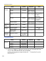
System Requirements for your PC
Your PC (Personal Computer) and network must meet the following technical
specifications for the camera to work properly.
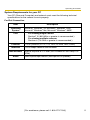
For IPv4 Connection
Item
Operating
System
CPU
Description
Microsoft® Windows® XP, Microsoft® Windows® 2000
Microsoft® Windows® Me, Microsoft® Windows® 98SE
•
•
For viewing single camera
Pentium® III (800 MHz or greater is recommended.)
For viewing multiple cameras
Pentium 4 (1.8 GHz or greater is recommended.)
Protocol
TCP/IP protocol (HTTP, TCP, UDP, IP, DNS, ARP, ICMP)
Interface
10/100 Mbps network card installed
Web Browser
Audio
Internet Explorer 6.0 or later (Not included on the Setup CDROM)
Audio input/output feature (Microphone or speaker)
[For assistance, please call: 1-800-272-7033]
5
Operating Instructions
For IPv6 Connection
Item
Operating
System
CPU
Description
Microsoft® Windows® XP Service Pack 1 or later
•
•
For viewing single camera
Pentium III (800 MHz or greater is recommended.)
For viewing multiple cameras
Pentium 4 (1.8 GHz or greater is recommended.)
Protocol
TCP/IP protocol (HTTP, TCP, UDP, IP, DNS, ICMPv6, NDP)
Interface
10/100 Mbps network card installed
Web Browser
Audio
Internet Explorer 6.0 or later (Not included on the Setup CDROM)
Audio input/output feature (Microphone or speaker)
Note
See Panasonic Network Camera support website at
http://panasonic.co.jp/pcc/products/en/netwkcam/ for the latest
information about web browser.
6
Operating Instructions
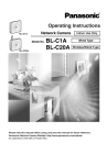
Camera Feature Locations
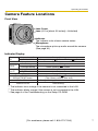
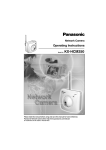
Front View
Lens Cover
Lens (0.5 m [about 20 inches]—Unlimited)
Indicator
The indicator color shows camera status.
Microphone
The microphone picks up audio around the camera.
(See page 30)
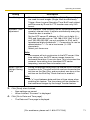
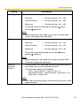
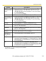
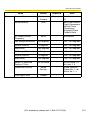
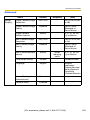
Indicator Display
Not on the LAN
Power
on
On the LAN
Normal Operation*1
Setting
Automatic
Setup
Finished setting
Using
Getting IP address*2
DHCP
Got IP address
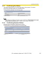
Updating Firmware
Pressing FACTORY
DEFAULT RESET button
UPnPTM Failure
Internal Failure
Orange blinking
Orange blinking
Green blinking
Green
Green
Green blinking
Green blinking
Green
Green blinking
Green
Orange blinking
Orange blinking
Turning off
(The camera restarts after that.)
Orange blinking (About a 2-second interval)
Red blinking*3
*1 The indicator turns orange if the camera is not connected to the LAN.
*2 The indicator blinks orange if the camera is not connected to the LAN.
*3 See page 4 of the Troubleshooting on the Setup CD-ROM.
[For assistance, please call: 1-800-272-7033]
7
Operating Instructions
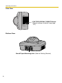
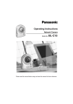
Side View
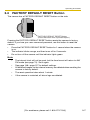
FACTORY DEFAULT RESET Button
Resets settings to default (see page
147).
Bottom View
Stand/Tripod Mounting Hole (See the Getting Started.)
8
Operating Instructions
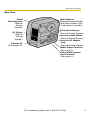
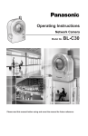
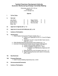
Rear View
Stand
Mounting Hole
(See the
Getting
Started.)
DC IN jack
(See the
Getting
Started.)
External I/O
(See page 145)
MAC Address
(See the Getting Started.)
and Serial number (S/N)
is indicated on the label.
Ethernet (LAN) port
(See the Getting Started.)
Hook for Audio Cables
(See the Getting Started.)
Hook for AC adaptor
Cord
(See the Getting Started.)
Audio Output Terminal
(See page 31)
External Microphone
Input Terminal
(See page 31)
[For assistance, please call: 1-800-272-7033]
9
Operating Instructions
Table of Contents
1
1.1
Accessing the Camera................................................................. 13
1.1.1
To Access the Camera in IPv6................................................................. 15
1.2
Viewing Single Camera page....................................................... 17
1.2.1
1.2.2
1.2.3
1.2.4
1.2.5
Auto Centering the Image (Click to Center) ............................................. 21
Capturing a Still Image ............................................................................ 22
Using Operation Bar ................................................................................ 23
Zooming In and Out ................................................................................. 25
Setting Home Position/Alarm Position/Preset Button .............................. 26
1.3
Listening to Camera Audio—Talking to the Camera .................... 30
1.4
Viewing Multi-Camera page ......................................................... 33
1.5
Viewing Buffered Image page ...................................................... 35
1.5.1
Deleting Buffered Images ........................................................................ 37
1.6
Viewing Still Images on Your Cell Phone ..................................... 38
2
10
Camera Monitoring .....................................................13
Various Camera Features ...........................................40
2.1
Using Camera Features ............................................................... 40
2.2
Connecting the Camera to Your IPv4 Network ............................ 43
2.3
Connecting the Camera to Your IPv6 Network ............................ 48
2.4
What is IPsec? ............................................................................. 52
2.5
Encrypt the Camera Image in Transport Mode ............................ 55
2.6
Encrypt the Camera Image in Tunnel Mode................................. 58
2.7
Using UPnP™ (Universal Plug and Play) .................................... 62
2.7.1
2.7.2
Connecting the Camera to a Router Supporting UPnP™ (IPv4 Only) .... 63
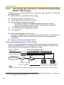
Connecting the Camera to a Router Not Supporting UPnP™ (IPv4 Only) ......... 64
2.8
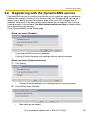
Registering with the DynamicDNS service .................................. 65
2.8.1
DynamicDNS Service (IPv4/IPv6) ........................................................... 68
2.9
Setting Date and Time ................................................................. 70
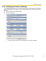
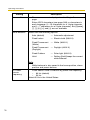
2.10
Changing Camera Settings.......................................................... 73
2.11
Adjusting Audio ............................................................................ 78
2.12
Changing Authentication Setting and Administrator User Name and
Password ..................................................................................... 80
2.13
Logging in to the Camera............................................................. 83
2.14
Creating, Modifying or Deleting General Users ........................... 84
Operating Instructions
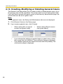
2.15
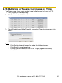
Buffering or Transferring Images by Timer ................................... 87
2.16
Buffering or Transferring Images by Alarm Signal........................ 96
2.17
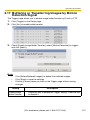
Buffering or Transferring Images by Motion Detection Signal .... 107
2.18
Transfer the Camera Image in Transport Mode.......................... 118
2.19
Transfer the Camera Image in Tunnel Mode .............................. 119
2.20
Setting the Motion Detection...................................................... 120
2.21
Notifying Setup of an Alarm Log ................................................ 123
2.22
Changing Initial Settings on the Single Camera page or the MultiCamera page ............................................................................. 125
2.23
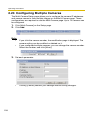
Configuring Multiple Cameras.................................................... 128
2.24
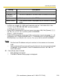
Specifying Operation Time......................................................... 130
2.25
Controlling External Output Terminal ......................................... 132
2.26
Changing Indicator Display ........................................................ 133
3
Camera Maintenance ................................................134
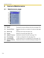
3.1
Maintenance page ..................................................................... 134
3.1.1
3.1.2
3.1.3
3.1.4
3.1.5
3.1.6
3.1.7
3.1.8
Confirming the Status............................................................................ 135
Confirming Session Status .................................................................... 135
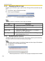
Displaying Alarm Logs........................................................................... 136
Restarting the Camera .......................................................................... 136
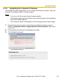
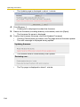
Updating the Camera Firmware ............................................................ 137
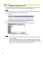
Creating Configuration File.................................................................... 140
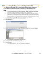
Loading Settings from a Configuration File ........................................... 141
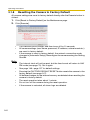
Resetting the Camera to Factory Default .............................................. 142
3.2
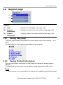
Support page ............................................................................. 143
3.2.1
3.2.2
3.2.3
Seeing Help page .................................................................................. 143
Seeing Product Information ................................................................... 143
Seeing Support Information................................................................... 144
3.3
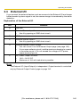
External I/O ................................................................................ 145
3.4
FACTORY DEFAULT RESET Button.......................................... 147
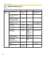
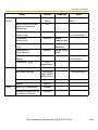
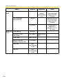
3.5
Default Setting List ..................................................................... 148
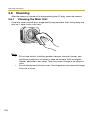
3.6
Cleaning..................................................................................... 158
3.6.1
Cleaning the Main Unit .......................................................................... 158
3.7
Setting an IP Address on Your PC ............................................. 159
3.8
Using Setup Program................................................................. 160
[For assistance, please call: 1-800-272-7033]
11
Operating Instructions
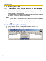
3.9
Setting Your PC.......................................................................... 164
3.9.1
3.9.2
3.9.3
Setting the Proxy Server Settings on Web Browser ............................. 164
Setting UPnP™ to Display Camera Shortcut in My Network Places ..... 167
Setting the Internet Temporary File Setting on Web Browser................ 167
3.10
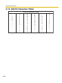
ASCII Character Table ............................................................... 168
3.11
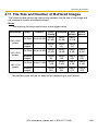
File Size and Number of Buffered Images ................................. 169
3.12
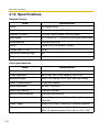
Specifications............................................................................. 170
Index..................................................................................173
12
Operating Instructions
1
Camera Monitoring
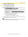
1.1
Accessing the Camera
1. Start up the web browser on your PC.
2. Enter "http://IPv4 Address (or URL):Port Number" on the address bar, and
press [Enter] on the keyboard.
•
When port number is 80 (default), you do not need to enter port number.
See page 45 for details about port number.
•
For IPv6 connection, see page 15 and page 16, and prepare the
requirements. Enter the "http://(IPv6-registered URL):Port Number" on
the address bar.
•
If the camera image is not displayed, see page 7, page 8 and page 9 of
the Troubleshooting on the Setup CD-ROM.
E.g. http://192.168.0.253:50000 (in IPv4)
http://XXXXX.viewnetcam.com:50000 (in IPv6)
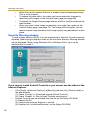
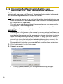
3. The Enter Network Password window is displayed, and enter the user name
and password that were set, and click [OK].
Note
When [Permit access from guest users] is set on the Security: Administrator
page, authentication window will not be displayed.
[For assistance, please call: 1-800-272-7033]
13
Operating Instructions
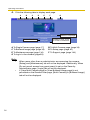
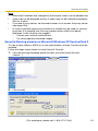
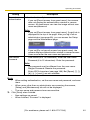
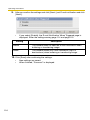
4. Click the following tabs to display each page.
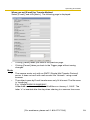
A
B
C
D
E
F
G
Select a language.
Version Number
A To Single Camera page (page 17)
C To Buffered Image page (page 35)
E To Maintenance page (page 134)
G To log in to the camera (page 83)
Displays IPv4, IPv6
or IPsec connection.
B To Multi-Camera page (page 33)
D To Setup page (page 40)
F To Support page (page 143)
Note
•
•
14
When users other than an administrator are accessing the camera,
[Setup] and [Maintenance] tab will not be displayed. Additionally, When
[Do not permit access from guest users] is set on the Security:
Administrator page, [Login] tab will not be displayed.
If [View Multi-Camera page] or [View Buffered Image page] is not
permitted on the General User page, [Multi-Camera] or [Buffered Image]
tab will not be displayed.
Operating Instructions
1.1.1
To Access the Camera in IPv6
You need to prepare the followings to access the camera in IPv6.
•
•
•
PC Requirements
Operating System: Windows XP Service Pack 1 or later
Web Browser: Internet Explorer 6.0 or later
An IPv6 Router
An IPv6 Connection Service
To connect in IPv6, subscribe to the ISP's "IPv4/IPv6 Dual-Stack" or "IPv6 over
IPv4 Tunneling" service. The camera does not work in IPv6-only network.
IPv6 Domain Name Service
In Windows XP, you cannot access the camera entering IP address on the web
browser. You need to enter IPv6 URL registered in the domain name service. We
recommend Viewnetcam.com service (see page 65) as a domain name service.
Ask your ISP about other IPv6 domain name service.
What is IPv6?
•
•
•
•
•
IPv6 is short for "Internet Protocol Version 6".
IPv6 was created to address the additional IP addresses that will be
needed as the Internet continues to expand.
IPv6 is expected to gradually replace IPv4, with the 2 coexisting for a
number of years during a transition period.
Though most ISPs (Internet Service Providers) do not yet support IPv6,
many local networks already use it. When your ISP supports IPv6, your
Panasonic Network Camera will be ready!
For more information you wish to visit http://www.ipv6.org/.
[For assistance, please call: 1-800-272-7033]
15
Operating Instructions
Setting up the IPv6 Router, your PC, and the Camera
Setting up the IPv6 Router
Set up the router as you subscribe to the IPv6 service. If the access from WAN side
is disabled on the router, enable the TCP packets from WAN side in the packet
filtering. See the Panasonic Network Camera support website at http://
panasonic.co.jp/pcc/products/en/netwkcam/ for information about the
recommended routers.
Setting up your PC
1. Click [Start]
•
[All Programs] [Accessories]
Command Prompt window is displayed.
[Command Prompt].
2. Enter "ipv6 install".
•
"Succeeded" is displayed.
Note
•
•
If Windows XP Service Pack 1 or later is not installed, "Succeeded" will
not be displayed. Install it on your PC.
When you use Windows XP Service Pack 2, click [Start] [Control
Panel] [Security Center] [Windows Firewall] [Advanced]
tab [Settings] button of ICMP in the Windows Firewall window, then
check [Allow incoming router request] check box in the ICMP Settings
window.
3. Enter "ipconfig".
•
If the IPv6 address is properly assigned to your PC, IPv6 address will be
displayed on the window.
Setting up the Camera
Usually, IPv6 address is automatically assigned. If you assign a static IPv6
address, see page 48. To access the camera in IPv6, you need to subscribe to the
domain name service such as Viewnetcam.com, and register the URL.
Confirming that You Can Access the Camera
Confirm that the image is properly displayed (see page 13).
16
Operating Instructions
1.2
Viewing Single Camera page
1. Access the camera (see page 13).
•
The Top page is displayed.
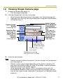
2. Click the [Single] tab at the top of the page.
•
•
When Security Warning window is displayed, click [Yes] (see page 18).
See page 19 for Security Warning window when using Microsoft Windows
XP Service Pack 2.
Audio Control
Bar (Talk Button,
Listen Button
and Adjustment
Bar)
(See page 30)
Click to Center
(See page 21)
Camera Image
The banner is
displayed.
(See page 20)
Capture Image
Button
(See page 22)
Operation Bar
(See page 23)
Digital Zoom
(See page 25)
Refresh
Interval
(See page 23)
Click the URL
when gray color
screen displayed.
Click the URL in case
of no audio.
Displaying to operate
with IPv4, IPv6, or IPsec.
3. Close the web browser.
Note
•
•
•
Refresh interval is [Motion] by default. You can change it on the operation
bar (see page 23).
Refresh interval may change depending on the network condition, PC
performance and what object you view. Using IPsec or enabling Motion
Detection will also slow refresh interval.
When displaying video (Motion JPEG), the camera allows up to 30
simultaneous accesses. When trying more than 30 accesses, the 31st
user will see a gray screen. (Maximum 30 accesses for a Buffered Image
page too.)
[For assistance, please call: 1-800-272-7033]
17
Operating Instructions
•
•
•
•
When the pan/tilt reaches the end, a shadow may be displayed partially.
This is not a problem.
To reduce the data traffic, the video can be automatically changed to
refreshing still images on the General User page (see page 84).
To display the Single Camera page directly, add it to the [Favorites] on the
web browser.
When you view a dark image, enable the color night view mode on the
Camera Setup page (see page 73). The image will be brighter, but the
refresh interval may slow down and image quality may decrease in a dark
place.
Security Warning window
To view a video (Motion JPEG) or to use audio feature, ActiveX® Controls must be
installed. When trying to display a video for the first time, Security Warning window
will be displayed. When using Windows XP or Windows 2000, log in as an
administrator to install it.
If you cannot install ActiveX Controls or you cannot see the video in the
Internet Explorer
•
•
18
Click [Tools] [Internet Options] [Security] tab and click [Custom level] on
the web browser.
(1) Check "Prompt" in "Download signed ActiveX Controls".
(2) Check "Enable" in "Run ActiveX Controls and plug-ins".
ActiveX Controls can be installed from the file on the Setup CD-ROM.
(1) Restart the PC.
(2) Confirm that Internet Explorer is closed.
(3) Double-click "ocx\ActiveXInst.exe" on the Setup CD-ROM.
Operating Instructions
Note
•
When the IP address was changed for the camera, enter it on the address bar.
•
Video may not be displayed quickly or audio may not be listened immediately.
Wait for a while.
•
If you use a proxy server, set the web browser not to access the proxy server
(see page 164).
•
In some corporate network environments a firewall may be used for security
purposes. It is possible that this may prevent motion video from being
displayed. In this situation we suggest:
– Contact your network administrator.
– Try using regularly refreshed images.
Security Warning window on Microsoft Windows XP Service Pack 2
To view a video (Motion JPEG) or to use audio feature, ActiveX Controls must be
installed.
Follow the steps shown below to install ActiveX Controls.
1. Click the warning displayed above the tabs, and click [Install ActiveX
Control...].
2. Click [Install].
[For assistance, please call: 1-800-272-7033]
19
Operating Instructions
The Banner
When the camera accesses the Internet, the banner displays product information
about cameras or announcements about the latest firmware, etc. from Panasonic.
Whether or not to display the banner can be set at Banner Display (see page 125).
Note
•
The banner is displayed when [Yes] is checked for Allow Access from the
Internet on the Automatic Setup page, or when [Enable] is checked for Auto
Port Forwarding on the UPnP page for the Connection Mode of Static or
DHCP.
•
Even if [Yes] is checked for Allow Access from the Internet on the Automatic
Setup page, or [Enable] is checked for Auto Port Forwarding on the UPnP page
for the Connection Mode of Static or DHCP, when the camera is not connected
to the Internet, is displayed.
20
Operating Instructions
1.2.1
Auto Centering the Image (Click to Center)
Using your mouse, click any portion of the camera image. As long as it is within the
pan/tilt range of the camera, the image will automatically move to place the
selected point in the center of the screen.
1. Move the cursor to the desired point.
Cursor
2. Click it.
•
•
The clicked point is centered.
See page 24 for the pan/tilt operation.
Note
•
•
•
•
When using the digital zoom feature, the Click to Center feature is
available.
When End Display appears on the operation bar, Click to Center does not
work beyond the pan/tilt end (see page 23).
The clicked position may slightly miss the center depending on the lens
direction.
If Click to Center is not permitted on the General User page (see page 84),
Click to Center does not work.
[For assistance, please call: 1-800-272-7033]
21
Operating Instructions
1.2.2
Capturing a Still Image
A still image can be saved on your PC.
1. Operate pan/tilt and select a resolution to display an image.
2. Click the capture image button.
Capture Image Button
•
The camera image opens in another window.
3. Right-click the image, and select [Save Picture As...].
•
Save as dialog box is displayed.
4. Specify a folder, and click [Save].
•
Camera image is saved in the folder.
5. Click [Close].
22
Operating Instructions
1.2.3
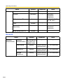
Using Operation Bar
End Display When the pan/tilt has reached the end (Left End,
and Preset Right End, Up End and Down End), End Display
Display:
appears. When clicking a preset button, the preset
name appears.
Pan/Tilt
Scan:
Moves the lens throughout the horizontal ( ) or
vertical ( ) range, and returns to the original
position.
Pan/Tilt/
Home
Position:
Controls lens direction. The camera can be set up
to turn to the home position when detecting
motions.
Pan ( : Left,
: Right), Tilt ( : Up,
: Down) and Home Position ( : Center
[Default])
Preset
Button:
Applies the camera direction to a preset position.
The camera can be set up to turn to the preset
positions when detecting motions. You can preset 8
positions (see page 26—page 29).
Alarm
Position:
When the external sensor detects a signal, the
camera can be set up to turn to this position. Only
an administrator can operate it (see page 26).
Brightness: Changes brightness in nine steps including [STD]
(Standard). Clicking [-] or [+] changes the image
brightness.
Output
Control:
Controls output signals of the External I/O.
Refresh
Interval:
Sets a refresh interval. (Motion—60-second
interval)
Resolution: Selects [640 x 480] or [320 x 240] (default) pixels.
Image
Quality:
Selects the image quality.
•
[Favor Clarity] optimizes the image for good
clarity.
•
[Standard] keeps the standard quality. (default)
•
[Favor Motion] optimizes the image for motion
display.
[For assistance, please call: 1-800-272-7033]
23
Operating Instructions
Note
When the camera image is not displayed correctly, click [Refresh] at the tool
bar on the web browser. The image will be refreshed.
Pan/Tilt Operation
Pan/tilt scan buttons automatically move the
lens horizontally from -60 ° to +60 ° and
vertically from -45 ° to +20 ° and return the
lens to the original position. Each pan/tilt
arrow moves the lens Up, Down, Right or Left,
and the home position button moves it to the
home position.
Pan/Tilt
Scan
Pan/Tilt
Pan/Tilt Range
Pan: -60 ˚ to +60 ˚
Tilt: -45 ˚ to +20 ˚
Note
When the pan/tilt reaches the end, a shadow may be displayed partially. This
is not a problem.
24
Operating Instructions
1.2.4
Zooming In and Out
Camera has a 10x digital zoom feature.
There are two methods of increasing/decreasing the size of the object on the
Single Camera screen, the Multi Camera screen, and the Buffered Image screen
(only while playing video):
1. Rotating the mouse wheel
Rotating the mouse wheel away from you zooms in, and rotating it towards
you zooms out.
2. Clicking the right mouse button
Clicking the right mouse button on the upper third of the Single Camera
screen zooms in, and clicking on the lower third of the Single Camera
screen zooms out.
Note
•
•
•
The Click to Center feature is available even while zooming in or out.
This feature is not available when viewing on a cell phone.
As the magnification increases, the image quality decreases.
Rotating the mouse wheel
On a screen, rotating the mouse wheel away from
you zooms in, and rotating it towards you zooms
out.
Zoom in
Zoom out
Note
The performance of the mouse varies according to your OS.
Clicking the right mouse button
Clicking the right mouse button on the upper third zooms in, and clicking on the
lower third zooms out. Zooming in and out is also available by moving the mouse
up with pressing the right mouse button, or moving the mouse down with pressing
the right mouse button.
Zoom in
Zoom out
[For assistance, please call: 1-800-272-7033]
25
Operating Instructions
1.2.5
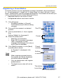
Setting Home Position/Alarm Position/Preset Button
Registering Home Position/Alarm Position
A home position or 2 alarm positions can be registered. When restarted, the
camera takes a home position. The alarm position is one that the camera turn to
when detecting alarms or motions. If the Lens Position When Triggered setting is
set (see page 98 or page 108), the camera takes an alarm position after the
External I/O detects a signal or the camera detects motions. See page 145 for the
External I/O.
1. Click [Program].
•
[Program] switches to [Cancel].
Click [Cancel] to quit without saving
changes.
2. Pan and tilt the camera to a desired
Home
Position
Pan/Tilt
position.
3. Click the home position button or the
Program
alarm position button.
4. Click [Save] to register, or click [Back]
and [Cancel] to cancel.
•
If "Success!" is displayed, click
[Back].
Note
The digital zoom value will not be saved.
26
Alarm
Position
Operating Instructions
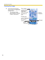
Registering a Preset Button
8 camera positions can be registered as presets. By default, the preset buttons
(1—4) are registered 1: Upper Left, 2: Upper Right, 3: Lower Left and 4: Lower
Right. These buttons can be changed (see page 29). The camera can be set up to
turn to the preset positions when detecting motions.
•
Registered buttons are shown in blue.
•
Unregistered buttons are shown in white.
1. Click [Program].
•
[Program] switches to [Cancel].
Click [Cancel] to quit without saving
changes.
2. Pan and tilt the camera to a desired
Pan/Tilt
position.
3. Click a preset button (1—8) to register.
E.g.:
Setting "Middle" for the preset 5.
4. Enter the preset name.
•
•
Maximum 15 characters.
Enter ASCII characters (see page
168) or characters in each
language. But [Space], ["], ['], [&], [<]
and [>] are not available.
5. Click [Save] to register, or click [Back]
and [Cancel] to cancel.
•
If "Success!" is displayed, click
[Back].
Note
•
•
•
Preset
When registering preset buttons,
the camera also saves brightness
and white balance settings.
Only an administrator can register
preset buttons.
The digital zoom value will not be
saved.
Preset
number
Setting
a name
The button
turns blue.
[For assistance, please call: 1-800-272-7033]
27
Operating Instructions
Viewing the Image
1. Click the home position,
alarm position or registered
preset button.
•
The camera takes
each position, and the
image is displayed.
The preset
name will be
displayed
when the lens
reaches an
end.
Putting the
cursor displays
the preset
name.
Alarm
Position
28
Home
Position
Preset
UpperLeft
Operating Instructions
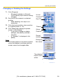
Changing or Deleting the Settings
1. Click [Program].
•
[Program] switches to [Cancel].
Click [Cancel] to quit without saving
changes.
2. Pan and tilt the camera to a desired
Home
Position
Pan/Tilt
position.
•
When deleting, this step is not
necessary.
3. Click the home position, alarm position
or a preset button (1—8).
4. Click [Save] after setting the preset
name or click [Delete].
•
If you quit to change or delete
settings, click [Back], and then
[Cancel].
•
If "Success!" is displayed, click
[Back].
Note
The home position or the alarm position
cannot be deleted, and these position
names cannot be changed either.
Preset
Alarm
Position
Preset
number
Changing
the name
The deleted
button turns
white.
[For assistance, please call: 1-800-272-7033]
29
Operating Instructions
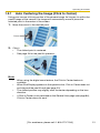
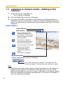
1.3
Listening to Camera Audio—Talking to the
Camera
1. Access the camera (see page 13).
•
The Top page is displayed.
2. Click the [Single] tab at the top of the page.
3. The Audio Control Bar (Talk Button, Listen Button and Adjustment Bar) is
displayed at the top of the screen. Listening or Talking is selected using the 2
icons. For general users, the feature must be enabled, otherwise it will not be
displayed.
Audio Feature
Listen Button
Talk Button
: You can talk from the
camera using the PC's
microphone. Clicking the
button temporarily stops
sending audio.
: The audio is stopped.
Clicking the button again
starts the Talk feature.
: You can listen to the audio
around the camera.
Clicking the button
temporarily stops the
audio.
: The audio is stopped.
Adjustment Bar
(Volume adjustment only for listening)
This slider adjusts the volume. To the right side, the
volume is larger. To the left side, the volume is smaller.
Note
•
Talk button and Listen button cannot be used simultaneously. Talk feature is
stopped during listening. Talk feature can be used only for a user. Listen
feature can be used for maximum 10 users. If the audio is interrupted, reduce
the max. bandwidth (see page 43 and page 48). In this case, the number of
users for listening are reduced.
30
Operating Instructions
•
•
•
•
•
•
•
•
•
•
Audio features such as camera microphone sensitivity and mute during pan/tilt
can be set up on the Audio page (see page 78).
If you are running other applications or opening multiple windows, the audio
may be interrupted or delayed.
When the image is refreshed during any operation such as preset registration
or a web browser refresh, the volume is reset to the default (midrange)
position. Audio that was muted is enabled.
The audio may be interrupted due to your PC's performance or network
environment. Reduce the max. bandwidth (see page 43 and page 48).
If the camera is accessed while the PC user visits other websites, the active
microphone may pick up audio from the PC's speakers. Be careful with it.
Talk feature cannot be used from a PC when the camera is accessed via a
proxy server.
If you cannot listen to the audio or talk from your PC, see page 14 of the
Troubleshooting on the Setup CD-ROM.
If you use external microphone, excessive length or poor quality microphone
cable can cause a degradation in audio quality.
The cables for the external microphone must be less than 7 m (about 23 feet)
long.
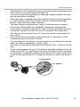
To talk to the camera from your PC, an external amplified speaker such as the
Panasonic RP-SPT70 or equivalent (customer-provided) must be connected
to the camera. The speaker connects to the camera with a stereo audio cable
similar to that used by your PC. Though the connector is stereo, the audio is
not.
For Microphone
For Speaker
MIC
EXTS
P
[For assistance, please call: 1-800-272-7033]
31
Operating Instructions
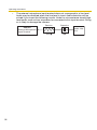
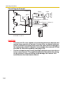
•
The external microphone input terminal does not correspond to a line level.
Audio may be distorted when the line level is input. Audio distortion will be
solved if you insert the following circuits. Under no circumstance should high
level audio, such as from a speaker, be connected to this input terminal. Doing
so is likely to damage the camera.
Resistor
Capacitor
Camera
Audio Line
Out
External Microphone
Input Terminal
33 K
32
1 F
Operating Instructions
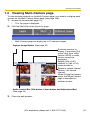
1.4
Viewing Multi-Camera page
To view multiple cameras on the Multi-Camera page, you need to configure each
camera on the Multi-Camera Setup page (see page 128).
1. Access the camera (see page 13).
•
The Top page is displayed.
2. Click the [Multi] tab at the top of the page.
•
Multi-Camera page can display up to 12 camera images.
Capture Image Button (See page 22)
Switches cameras to
display. If you select [All]
at the View Type, video
(Motion JPEG) or audio
buttons cannot be
displayed.
Selects [320 x 240]
(default) or [160 x 120]
pixels resolution.
Selects a refresh interval
(Motion—60-second
interval).
When clicking the camera
name, the Single Camera
page is displayed on
another window.
Audio Control Bar (Talk button, Listen button and Adjustment Bar)
(See page 30)
3. Close the web browser.
[For assistance, please call: 1-800-272-7033]
33
Operating Instructions
Note
•
•
•
•
•
•
•
•
•
When selecting [All] at the View Type, all images are displayed in 160 x
120 pixels resolution, and the Audio Control Bar is not displayed.
640 x 480 pixels image cannot be displayed on the Multi-Camera page.
When viewing video (Motion JPEG), we recommend using an Ethernet
switching hub instead of the repeater hub to prevent degradation in video
display.
Due to the network congestion or the number of accesses, the refresh
interval may slow down.
When the refresh interval is slow, restrict the bandwidth on the Network
page (see page 46 and page 51). The refresh interval may be improved.
To reduce the data traffic, the video can be automatically changed to
refreshing still images on the General User page (see page 84).
When viewing 4 cameras on the Multi-Camera page, you may need 3 to 4
Mbps bandwidth. If the bandwidth is not enough, the refresh interval may
slow down.
The digital zoom can be used. (only for video)
Click to Center feature can be used while using the digital zoom.
When the image is not displayed on the Multi-Camera page
•
•
•
Confirm that the Internet IP address is specified for each camera and that each
camera is connected to the Internet. For Internet access, local IP addresses
(192.168.xxx.xxx) cannot be used.
Confirm the settings on the Multi-Camera Setup page (see page 128).
Confirm that the web browser is not accessing the proxy server (see page
164).
When setting [Do not permit access from guest users] on the
Security: Administrator page
•
•
34
An authentication window is displayed in camera access. Enter the
administrator's or the general user's user name and password.
When you view the images on the Multi-Camera page, all authentication
windows of the configured cameras are displayed. Enter the administrator's or
the general user's user name and password registered for each camera.
Operating Instructions
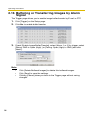
1.5
Viewing Buffered Image page
To buffer the images on the internal memory, you need to set up image transfer
settings (see page 87, page 96 or page 107). You can view buffered images on this
Buffered Image page.
Note
Sound cannot be buffered on the Buffered Image page.
1. Access the camera (see page 13).
•
The Top page is displayed.
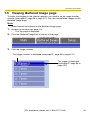
2. Click the [Buffered Image] tab at the top of the page.
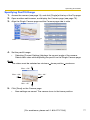
3. Click the trigger number.
The trigger number is displayed (see page 87, page 96 or page 107).
The trigger is displayed
(see page 87, page 96 or
page 107).
[For assistance, please call: 1-800-272-7033]
35
Operating Instructions
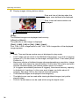
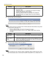
4. Display images clicking buttons below.
Date and time of the day when the
images were buffered are displayed.
Date, time and frame number are
displayed.
[Play]:
The buffered images are displayed continuously.
[<Prev] or [Next>]:
The previous or next image is displayed.
[First], [<100], [<10] or [10>], [100>], [Last]:
First, 10th, 100th, image before or last, 10th, 100th image after of the displayed
image appears.
Note
•
Date, Time and frame number are not displayed in play mode.
•
A still image can be saved on the Buffered Image page, if you are not playing
images on it. Put the cursor on the image, and right-click it. Then select [Save
Picture As...].
•
Maximum number of buffered images change depending on resolution, image
quality and what object the camera buffers. At the 320 x 240 pixels resolution
and the standard quality, the camera buffers about 125 frames.
(If 3 triggers are enabled [maximum 5 triggers], the internal memory capacity
is divided into 3 sections. In this case, each trigger can buffer about 40
images.) See page 169 for the internal memory capacity.
•
The buffered images are displayed chronologically.
•
The digital zoom can be used while viewing buffered images (only while
playing video).
•
Click to Center feature can be used while using the digital zoom.
36
Operating Instructions
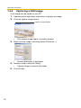
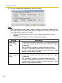
1.5.1
Deleting Buffered Images
If you intend to delete images for each transfer condition, click [Delete Buffered
Images] on the Trigger page (see page 87, page 96 or page 107).
Note
•
If you are buffering images on the internal memory, the following operations
also delete all buffered images.
– Turning off the camera.
– Saving the Date and Time page.
– Restarting, updating firmware or resetting the camera to factory default.
– Changing the setting for [Enable Image Buffer/Transfer]. (See page 87,
page 96 or page 107)
[For assistance, please call: 1-800-272-7033]
37
Operating Instructions
1.6
Viewing Still Images on Your Cell Phone
You can view still images over the Internet from a compatible cell phone.
Enter "http://IP address (or URL):Port Number/mobile" on a cell phone and
press [OK].
•
When the port number is set to 80 (default), it is not required.
E.g. http://202.208.167.XXX:50000/mobile
(or XXXXX.viewnetcam.com:50000/mobile)
•
•
•
The camera must be allowed the Internet access for cell phone access.
When an authentication window is displayed, enter the administrator's or the
general user's user name and password.
A still image is displayed. (Video [Motion JPEG] cannot be displayed.)
Pressing 2, 4, 6 or 8 on the cell phones allows
you to pan or tilt the camera in four directions:
Left, Up, Down or Right.
Pressing 5 will refresh the image.
160 x 120 resolution is displayed at the first
access. Pressing 0 switches the resolution to 320
x 240.
Executing [Home Position] moves the lens to the
home position.
Pressing 1, 3, 7 or 9 on the keypad allows you to
use the first four registered preset buttons.
Registered presets 5—8 are available by
activating the link on the cell phone page.
Displays up to 50 Logs in order of time, and only
when logging in as an administrator.
Go to the control page when clicking.
Displays the number of new logs.
Displays the date and time, the kind of signal and
sensor.
Go to the control page when clicking.
38
Operating Instructions
Note
•
Audio feature does not work on cell phones.
•
If the features are not permitted on the General User page, the buttons related
with the features are not displayed. (See page 84)
•
If the image is not displayed properly, try the following 2 URLs.
1. http:// IP address(or URL):Port Number/MobileH for HTML.
(or XXXXX.viewnetcam.com:50000/MobileH)
2. http:// IP address(or URL):Port Number/MobileX for XHTML.
(or XXXXX.viewnetcam.com:50000/MobileX)
•
When pan/tilt reaches the end, the keypad number and character disappear.
E.g.: The pan reaches the left end.
"(4)L" disappears.
•
•
Some cell phones are not compatible with Panasonic Network Cameras.
Some phones may allow viewing only on port 80, and some may not support
password authentication. See the Panasonic Network Camera support
website at http://panasonic.co.jp/pcc/products/en/netwkcam/ for a cell
phone model list, and the compatibility level which has been verified with the
Panasonic Network Camera.
Some cell phones display images not at the specified resolution but at a
decreased size.
[For assistance, please call: 1-800-272-7033]
39
Operating Instructions
2
Various Camera Features
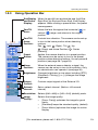
2.1
Using Camera Features
1. Access the camera (see page 13).
•
The Top page is displayed.
Note
•
•
•
When [Permit access from guest users] is set on the Security:
Administrator page, click [Login] tab and log in as an administrator.
When users other than an administrator are accessing the camera, the
[Setup] and [Maintenance] tabs are not displayed.
If [View Multi-Camera page] or [View Buffered Image page] is not
permitted on the General User page, [Multi-Camera] or [Buffered Image]
tab will not be displayed.
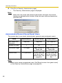
2. Click [Setup] tab at the top of the page.
(1)
(2)
(3)
(4)
(5)
(6)
(7)
(8)
(9)
(10)
(11)
(12)
(13)
(14)
(15)
(16)
(17)
(18)
40
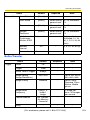
Operating Instructions
Basic
(1)
Network (IPv4) Configures the IPv4 network settings to connect the
camera to the network (see page 43).
(2)
Network (IPv6) Configures the IPv6 network settings to connect the
camera to the network (see page 48).
(3)
IPsec
Enables IPsec (Transport or Tunnel mode) (see page 52).
(4)
UPnP
Enables automatic port forwarding or shortcut to the
camera (see page 62).
(5)
DynamicDNS
Registers with the DynamicDNS service (see page 65).
(6)
Date and Time
Sets the date and time, automatic time adjustment and
adjust clock for daylight saving time settings (see page 70).
(7)
Camera
Sets camera name, white balance, pan/tilt range, return to
specified position and color night view settings (see page
73).
(8)
Audio
Sets output, volume, PC audio input timeout, input, camera
microphone sensitivity and mute during pan/tilt settings
(see page 78).
Account
(9)
Administrator*1 Sets authentication setting and administrator security (user
name and password) (see page 80).
(10)
General User*1
Sets general user security (user name and password) and
general user's access level (see page 84).
Buffer/Transfer
(11)
Trigger
Sets image buffer or transfer by timer or alarm or motion
detection. (See page 87, page 96 or page 107)
(12)
Motion
Detection
Sets the threshold and the sensitivity (see page 120).
(13)
Alarm Log
Sets the information to notify the log by e-mail (see page
123).
[For assistance, please call: 1-800-272-7033]
41
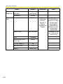
Operating Instructions
Advanced
(14)
Image Display
Sets resolution, image quality and refresh interval of Single
Camera and Multi-Camera page, time stamp setting,
language and banner (see page 125).
(15)
Multi-Camera*1
Sets the camera IP address or host name, camera name on
the Multi-Camera page (maximum 12 cameras) (see page
128).
(16)
Operation
Time
Sets time period to display camera images (see page 130).
(17)
External
Output
Sets the digital output terminal of the External I/O (see
page 132).
(18)
Indicator
Control
Sets indicator display (see page 133).
*1
42
If you change [Administrator], [General User], or [Multi-Camera Setup page] settings,
changes will not be applied to the video (Motion JPEG) viewers. Restart the camera to make
changes applied to all video viewers.
Operating Instructions
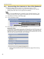
2.2
Connecting the Camera to Your IPv4 Network
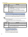
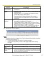
The Network page offers three options to configure the camera in IPv4.
•
[Automatic Setup] automatically assigns an unused IP address to the camera,
and uses UPnPTM (Universal Plug and Play) to configure your router.
•
[Static] allows the user to use a specific IP address.
•
[DHCP] is offered for ISPs who require this option.
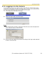
1. Click [Network (IPv4)] on the Setup page.
2. Click a connection mode.
Normally sets Automatic Setup.
Uses a static IP address.
Uses ISP DHCP server function.
•
Each page is displayed (see page 43—page 44).
3. Enter each parameter in the proper data field.
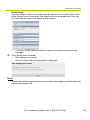
Automatic Setup
The camera automatically obtains the network settings (subnet mask, default
gateway and DNS server address) utilizing a DHCP feature on the router. The
camera also automatically searches the unused IP address on your network.
If you select [Yes] at the Allow Access from the Internet, the camera
automatically enables port forwarding by using UPnPTM. In this case, the
camera automatically searches the unused port number on your network in the
order from 50000 to 50050.
•
Clicking [Cancel] takes you back to the previous page without saving
changes.
[For assistance, please call: 1-800-272-7033]
43
Operating Instructions
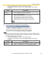
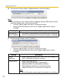
DHCP Setup
•
Static Setup
Clicking [Cancel] takes you back to the previous page without
saving changes.
4. Click [Save] when finished.
•
•
New settings are saved.
When finished, the following page is displayed.
Note
The current network settings are shown on the Status page in the Maintenance
section (see page 135).
5. Click [Restart].
•
•
•
44
The camera restarts, and the Top page is displayed.
If the camera is restarted, all buffered images on the internal memory are
deleted.
Checking [Yes] for [Allow Access from the Internet] on [Automatic Setup]
may not display the Top page, because the port number may change. Use
the Setup Program to access the camera.
Operating Instructions
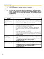
Note
When you do not know the camera IP address while setting [Automatic Setup]
or [DHCP Setup], you can search it by using the Setup Program (see page
160).
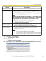
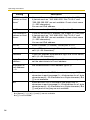
Setting
Allow Access from
the Internet
(Automatic Setup
Only)
Description
•
Allow Access from the Internet setting automatically
configures the router's Port Forwarding setting (some
routers call it "Address Translation", "Static IP
Masquerade", "Virtual Server" or "Port Mapping"). To
enable Internet access to the camera, check [Yes]. In this
case, the camera automatically searches the unused port
number on your network in the order from 50000 to 50050.
To disable Internet access to the camera, check [No].
Network
•
Configuration from
Setup Program
(Static/DHCP Only)
If you prohibit the Setup Program from changing the
network settings, clear the check box.
Port Number
•
(Static/DHCP Only)
The port number is 80 by default. When you use multiple
cameras with a router on your network, each camera must
be assigned its own port number (see page 64 "2.7.2
Connecting the Camera to a Router Not Supporting
UPnP™ (IPv4 Only)").
Do not set the following port numbers.
E.g., FTP: 20 and 21, Telnet: 23, SMTP: 25, DNS: 53,
POP3: 110, HTTPS: 443, ICQ: 4000 and IRC: 6661—
6667.
Enter only the number (1—65535).
Some ISPs do not allow you to use port 80. Ask your ISP
or network administrator about the accessible port number
over the Internet.
•
•
•
•
IP address
•
Subnet Mask
(Static Only)
•
•
•
If your ISP or network administrator specifies the IP
address and subnet mask, enter them in each data field.
If you use the camera on the LAN, set the IP address in the
same class as your PC (see page 159).
Set 4 digits (0—255) and 3 periods such as
"192.168.0.253". But "0.0.0.0" and "255.255.255.255" are
not available.
[For assistance, please call: 1-800-272-7033]
45
Operating Instructions
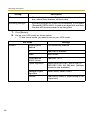
Setting
Host Name
(DHCP Only)
Description
•
•
If your ISP uses the DHCP function which automatically
assigns the IP address to the camera, enter the ISPassigned host name. (Host name may be used as an
authentication.)
Enter ASCII characters for the host name (see page 168).
But [Space], ["], ['], [&], [<] and [>] are not available.
Default Gateway*1
•
(Static/DHCP Only)
•
If you have the assigned Default Gateway address by your
ISP or network administrator, enter it in this data field.
Set 4 digits (0—255) and 3 periods such as
"192.168.0.253". But "0.0.0.0" and "255.255.255.255" are
not available.
DNS Server
•
Address*1
(Static/DHCP Only)
DNS server address is required in the following conditions.
– Transferring camera images by E-mail or FTP
– Setting cameras by their host names on the MultiCamera Setup page
– Using the DynamicDNS service
– Using the alarm log notification
If you have the assigned DNS server addresses by your
ISP or network administrator, enter them in this data field.
They usually have two addresses.
Set 4 digits (0—255) and 3 periods such as
"192.168.0.253". But "0.0.0.0" and "255.255.255.255" are
not available.
•
•
Max. Bandwidth
Usage
•
•
•
The bandwidth can be restricted.
Select the maximum bandwidth usage from [Unlimited] to
[0.1 Mbps].
This setting is valid in both IPv4/IPv6.
Note
Set the maximum bandwidth usage seeing the following
file sizes. These are examples for a JPEG file with a
standard image quality. File sizes may change depending
on the image quality or how bright the object is.
160 x 120 pixels: About 3.5 KB (28 Kbit)
320 x 240 pixels: About 10 KB (80 Kbit)
640 x 480 pixels: About 18 KB (144 Kbit)
46
Operating Instructions
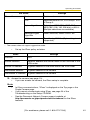
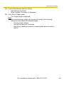
Setting
Connection Type
Description
•
•
*1
Select [Auto Negotiation] normally. If you cannot access
the camera, see page 7 of the Troubleshooting on the
Setup CD-ROM.
This setting is valid in both IPv4/IPv6.
If you automatically obtain the IP address from the DHCP server, you do not need to set it.
[For assistance, please call: 1-800-272-7033]
47
Operating Instructions
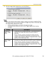
2.3
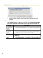
Connecting the Camera to Your IPv6 Network
The Network page offers two options to configure the camera in IPv6.
•
[Automatic Setup] automatically assigns an IPv6 address to the camera.
•
[Static] allows the user to use a specific IPv6 address.
Note
IPv6 is the expanded protocol created for future Internet expansion. Your
network and your ISP must support IPv6 before you can use this feature.
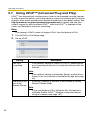
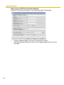
1. Click [Network (IPv6)] on the Setup page.
2. Click a connection mode.
Normally sets Automatic Setup.
Uses a static IP address.
3. Enter each parameter in the proper data field.
Automatic Setup
The camera is automatically assigned an IPv6 prefix from the IPv6 router, and
produces the original IPv6 address from the IPv6 prefix. If you select [No] at
the Allow Access from the Internet, the camera can be accessed only from the
LAN that has the same IPv6 prefix as the camera.
•
48
Clicking [Cancel] takes you back to the previous page without saving
changes.
Operating Instructions
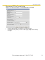
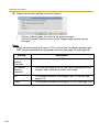
Static Setup
You can assign a static IPv6 address to the camera. If you select [No] at the
Allow Access from the Internet, the camera can be accessed only from the
LAN that has an same IPv6 prefix as the camera.
•
Clicking [Cancel] takes you back to the previous page without saving
changes.
4. Click [Save] when finished.
•
•
New settings are saved.
When finished, the following page is displayed.
Note
The current network settings are shown on the Status page in the Maintenance
section (see page 135).
[For assistance, please call: 1-800-272-7033]
49
Operating Instructions
5. Click [Restart].
•
The camera restarts, and the Top page is displayed.
Note
•
•
When you do not know the camera IP address while setting [Automatic
Setup], you can search it by using the Setup Program (see page 160). Or
you can search it on the Status page (see page 135) after accessing the
camera in IPv4.
If the camera is restarted, all buffered images on the internal memory are
deleted.
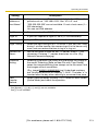
Setting
Allow Access from
the Internet
(Automatic Setup
Only)
Description
•
If [Yes] is selected at the Allow Access from the Internet,
you can access the camera from the Internet. If [No] is
selected, the camera can be accessed only from the LAN
that has the same IPv6 prefix as the camera.
Port Number (Static •
Only)
•
The port number is 80 by default. The port number must be
unique for each terminal on your network.
Do not set the following port numbers.
E.g., FTP: 20 and 21, Telnet: 23, SMTP: 25, DNS: 53,
POP3: 110, HTTPS: 443, ICQ: 4000 and IRC: 6661—
6667.
Enter only the number (1—65535).
Some ISPs do not allow you to use port 80. Ask your ISP
or network administrator about the accessible port number
over the Internet.
•
•
IP address
(Static Only)
•
•
Default Gateway
(Static Only)
•
•
50
Enter a global address. You do not need to enter prefix
length.
IPv6 address consists of 8 hexadecimal digits divided with
":". Consecutive 0s can be abbreviated as "::".
(E.g. 2001:2:3:4::5)
If you have the assigned Default Gateway IPv6 address by
your ISP or network administrator, enter it in this data field.
IPv6 address consists of 8 hexadecimal digits divided with
":". Consecutive 0s can be abbreviated as "::".
(E.g. 2001:2:3:4::5)
Operating Instructions
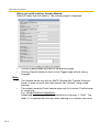
Setting
DNS Server
Address
Description
•
•
•
Max. Bandwidth
Usage
•
•
•
DNS server address is required in the following conditions.
– Transferring camera images by E-mail or FTP
– Setting cameras by their host names on the MultiCamera Setup page
– Using the DynamicDNS service
– Using the alarm log notification
If you have the assigned DNS server IPv6 addresses by
your ISP or network administrator, enter them in this data
field. They usually have two addresses.
IPv6 address consists of 8 hexadecimal digits divided with
":". Consecutive 0s can be abbreviated as "::".
(E.g. 2001:2:3:4::5)
The bandwidth can be restricted.
Select the maximum bandwidth usage from [Unlimited] to
[0.1 Mbps].
This setting is valid in both IPv4/IPv6.
Note
Set the maximum bandwidth usage seeing the following
file sizes. These are examples for a JPEG file with a
standard image quality. File sizes may change depending
on the image quality or how bright the object is.
160 x 120 pixels: About 3.5 KB (28 Kbit)
320 x 240 pixels: About 10 KB (80 Kbit)
640 x 480 pixels: About 18 KB (144 Kbit)
Connection Type
•
•
Select [Auto Negotiation] normally. If you cannot access
the camera, see page 7 of the Troubleshooting on the
Setup CD-ROM.
This setting is valid in both IPv4/IPv6.
[For assistance, please call: 1-800-272-7033]
51
Operating Instructions
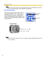
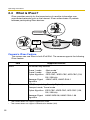
2.4
What is IPsec?
IPsec provides security for the transmission of sensitive information over
unprotected networks such as the Internet. IPsec authenticates IP packets
between participating IPsec devices.
Unreadable
Malicious User
Image
Allowed User
Internet
Readable
Camera's IPsec Feature
The camera can use IPsec in both IPv4/IPv6. The camera supports the following
IPsec feature.
Item
IKEv1
Supported Feature
Pre-shared Key Method
Phase 1 mode
: Main mode*1
Phase 2 mode
: Quick mode
Cipher Algorithm : DES-CBC, 3DES-CBC, AES-CBC (128,
192, 256 bits)
Message-Digest : HMAC-MD5, HMAC-SHA-1
Algorithm
IPsec
ESP (Encapsulating Security Payload)*2
Transport mode, Tunnel mode
Cipher Algorithm :DES-CBC, 3DES-CBC, AES-CBC (128,
192, 256 bits)
Message-Digest :HMAC-MD5-96, HMAC-SHA-1-96
Algorithm
*1
*2
52
The camera does not support aggressive mode.
The camera does not support authentication header (AH).
Operating Instructions
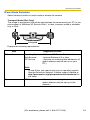
IPsec Mode Selection
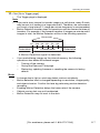
Select transport mode or tunnel mode to access the camera.
Transport Mode (IPv4 Only)
The image is encrypted in the whole way between the camera and your PC. In the
environment of Windows XP Service Pack 1 or later, transport mode is available
only in IPv4.
Transport Mode
Encrypted
Prepare the following requirements.
Item
PC
Supported Feature
Operating System : Windows XP Service Pack 1 or later
Web Browser
: Internet Explorer 6.0 or later
ISP Service
: Services for multiple global addresses (A
global address must be set up on your
PC.)
Note
To use IPsec, you need to set up your operating system.
See the Panasonic Network Camera support website at
http://panasonic.co.jp/pcc/products/en/netwkcam/ for
the setup.
Camera
ISP Service
: Services for multiple global addresses (A
global address must be set up to the
camera.)
[For assistance, please call: 1-800-272-7033]
53
Operating Instructions
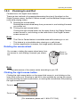
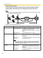
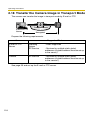
Tunnel Mode (IPv4/IPv6)
An IPsec mode of operation where the entire IP packet including IP header is
authenticated and encrypted. A new IP header is added (protecting the entire
original packet). Both VPN clients and VPN gateways can use this mode.
Note
The camera can be accessed only from the PCs under the VPN router. Other
PCs cannot access the camera.
LAN
WAN
Tunnel Mode
Not Encrypted
Encrypted
Prepare the following requirements.
Item
Supported Feature
PC
Operating System : Windows XP, Windows 2000, Windows
Me, Windows 98SE (in IPv4)
: Windows XP Service Pack 1 or later (in
IPv6)
Web Browser
: Internet Explorer 6.0 or later
Router
ISP Service
(in IPv4)
ISP Service
(in IPv6)
: Static global address service (A global
address must be set up to the WAN side of
the router.)
: "IPv4/IPv6 Dual-Stack" or "IPv6 over IPv4
Tunneling" service
Note
See the Panasonic Network Camera support website at
http://panasonic.co.jp/pcc/products/en/netwkcam/ for
the recommended router.
Camera
ISP Service
(in IPv4)
ISP Service
(in IPv6)
54
: Services for multiple global addresses (A
global address must be set up to the
camera.)
: "IPv4/IPv6 Dual-Stack" or "IPv6 over IPv4
Tunneling" service
Operating Instructions
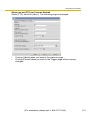
2.5
Encrypt the Camera Image in Transport Mode
The camera can encrypt the image using IPsec transport mode.
Note
If you use IPsec, refresh interval slows down.
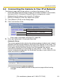
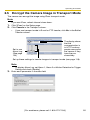
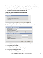
1. Click [IPsec] on the Setup page.
2. Click Camera in the Transport column.
•
If you use transport mode in E-mail or FTP transfer, click No. in the Buffer/
Transfer column.
The display shows
that the
communication is
in HTTP and any
people can access
the camera if they
have the preshared key.
Set to use
Alarm Log.
(See page
123)
Set up these settings to transfer images in transport mode (see page 118).
Note
To display Alarm Log, set Alarm 1, Alarm 2 or Motion Detection for Trigger
Setting and check [Enable].
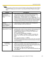
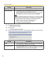
3. Enter each parameter in the data field.
[For assistance, please call: 1-800-272-7033]
55
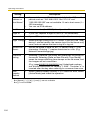
Operating Instructions
Setting
Description
Status
•
Pre-Shared Key
•
Check the box to use this encryption method.
It is the key to use in the authentication of communications.
Enter the same pre-shared key as your PC.
•
Enter ASCII characters for the host name (see page 168).
But [Space], ["], ['], [&], [<] and [>] are not available.
Note
If the pre-shared key leaks to a third party, it may lead to illegal
access, private information leak or interference. To protect your
security and privacy, pay attention to the following points.
•
Make it known only to the specified people.
•
Set it as many characters as possible.
•
Change the password regularly.
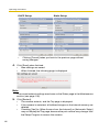
4. Click [Save] when finished.
•
New settings are saved.
5. Click [Cancel].
•
The IPsec page is displayed.
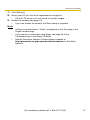
6. Check [Use] in the IPsec column, check encoding strength, and click [Save].
Setting
56
Description
IPsec
•
Check the box to enable IPsec features. If you clear the
box, whole IPsec features will be invalid.
Encoding strength
•
Encoding strength for IPsec can be selected. If you select
[Standard], DES or NULL is valid as an algorithm, and then
the data will become easier to be decrypted.
Operating Instructions
7. Click [Restart].
8. Set up your PC as it fits to the requirements on page 53.
•
Set the FTP server or E-mail server to transfer images.
9. Access the camera (see page 13).
•
If you can access the camera, the IPsec setup is complete.
Note
•
•
•
In IPsec communications, "IPsec" is displayed on the Top page or the
Single Camera page.
If you cannot communicate using IPsec, see page 20 of the
Troubleshooting on the Setup CD-ROM.
See the Panasonic Network Camera support website at
http://panasonic.co.jp/pcc/products/en/netwkcam/ for the IPsec
features.
[For assistance, please call: 1-800-272-7033]
57
Operating Instructions
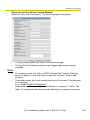
2.6
Encrypt the Camera Image in Tunnel Mode
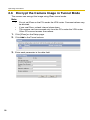
The camera can encrypt the image using IPsec tunnel mode.
Note
•
•
•
Do not set IPsec on the PCs under the VPN router. Communications may
be blocked.
If you use IPsec, refresh interval slows down.
The camera can be accessed only from the PCs under the VPN router.
Other PCs cannot access the camera.
1. Click [IPsec] on the Setup page.
2. Click Add in the Tunnel column.
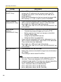
3. Enter each parameter in the data field.
58
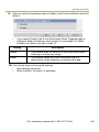
Operating Instructions
Setting
Description
Status
•
Check the box to use this encryption method.
Pre-Shared Key
•
Network address
•
•
Enter the destination network address.
Enter "IP address/Prefix length" in the data field.
Router address
•
Enter the WAN IP address of the VPN router on a
destination network.
It is the key to use in the authentication of communications.
Enter the same pre-shared key as your VPN router.
•
Enter ASCII characters for the host name (see page 168).
But [Space], ["], ['], [&], [<] and [>] are not available.
Note
If the pre-shared key leaks to a third party, it may lead to illegal
access, private information leak or interference. To protect your
security and privacy, pay attention to the following points.
•
Make it known only to the specified people.
•
Set it as many characters as possible.
•
Change the password regularly.
Note
•
•
IPv6 link-local address is not available.
The camera can be accessed only from the PCs under
the VPN router. Other PCs cannot access the camera.
4. Click [Save] when finished.
•
New settings are saved.
5. Click [Cancel].
•
The IPsec page is displayed.
6. Check [Use] in the IPsec column, check encoding strength, and click [Save].
[For assistance, please call: 1-800-272-7033]
59
Operating Instructions
Setting
Description
IPsec
•
Check the box to enable IPsec features. If you clear the
box, whole IPsec features will be invalid.
Encoding strength
•
Encoding strength for IPsec can be selected. If you select
[Standard], DES or NULL is valid as an algorithm, and then
the data will become easier to be decrypted.
7. Click [Restart].
8. Set up your VPN router as shown below.
•
To use tunnel mode, you need to set up your VPN router.
IKE Items
Phase 1
60
Settings
Authentication
Method
Pre-shared Key Method
ID
Specifies by address.
Mode
Main mode*1
Diffie-Hellman
MODP Group
Specifies 1 or 2.
Cipher Algorithm
Select from DES-CBC, 3DES-CBC or
AES-CBC (128, 192, 256 bits). (Multiple
selections are available.)
Message-Digest
Algorithm
HMAC-MD5, HMAC-SHA-1
Lifetime
Specifies by 28800 s (Byte setting is not
supported.)
Operating Instructions
IKE Items
Phase 2
*1
Settings
Mode
Quick mode
PFS
Specifies either of Off, D-H Group 1 or DH Group 2.
Cipher Algorithm
Select from DES-CBC, 3DES-CBC,
AES-CBC (128, 192, 256 bits) or NULL.
(Multiple selections are available.)
Message-Digest
Algorithm
HMAC-MD5-96, HMAC-SHA-1-96
Lifetime
Specifies by 28800 s (Byte setting is not
supported.)
The camera does not support aggressive mode.
•
Set up the IPsec policy as below.
Items
Settings
Protocol
ANY
Source Network
Network address and subnet mask on the LAN side of the
VPN router
Source IP address
A global address on the WAN side of the VPN router
Destination Network
A global address of the camera
Destination IP address A global address of the camera
9. Access the camera (see page 13).
•
If you can access the camera, the IPsec setup is complete.
Note
•
•
•
In IPsec communications, "IPsec" is displayed on the Top page or the
Single Camera page.
If you cannot communicate using IPsec, see page 20 of the
Troubleshooting on the Setup CD-ROM.
See the Panasonic Network Camera support website at
http://panasonic.co.jp/pcc/products/en/netwkcam/ for the IPsec
features.
[For assistance, please call: 1-800-272-7033]
61
Operating Instructions
2.7
Using UPnP™ (Universal Plug and Play)
UPnPTM can automatically configure your router to be accessed from the Internet.
In order to use this feature, your router needs to support this feature and it must be
enabled. Most router manufacturers disable this feature as the default setting. See
http://panasonic.co.jp/pcc/products/en/netwkcam/ for details and see your
router's manual for how to enable UPnPTM. After the UPnPTM is enabled on the
router, set [Enable] for auto port forwarding.
Note
The camera's UPnPTM does not support IPv6. Use this feature in IPv4.
1. Click [UPnP] on the Setup page.
2. Set up UPnP.
Setting
Auto Port
Forwarding
Description
•
If the network setting is [Static] or [DHCP], enabling auto
port forwarding allows you to access the camera from the
Internet.
Note
If the network setting is [Automatic Setup], enable [Allow
Access from the Internet] on the Network page (see page
45).
Display Shortcut •
Icon in My
Network Places
Enabling it displays a shortcut to the camera in the My
Network Places folder.
Note
If you use Windows XP or Windows Me, this feature is
available. Enable UPnPTM Windows component before
using this feature (see page 167).
62
Operating Instructions
3. Click [Save] when finished.
•
•
New settings are saved.
When finished, "Success!" is displayed.
4. Click [Go to UPnP page].
•
2.7.1
The UPnP page is displayed.
Connecting the Camera to a Router Supporting
UPnP™ (IPv4 Only)
To allow access from the Internet with a router supporting UPnPTM, follow the
procedures shown on the Getting Started.
Note
•
•
In some routers, the UPnPTM feature is disabled by default. Enable your
router's UPnPTM feature following the router manual before you set up the
camera. See the Panasonic Network Camera support website at http://
panasonic.co.jp/pcc/products/en/netwkcam/ for details.
If the maximum idle time is set in PPPoE or PPTP connection with your
ISP, disable it on the router. See the router manual for details.
[For assistance, please call: 1-800-272-7033]
63
Operating Instructions
2.7.2
Connecting the Camera to a Router Not Supporting
UPnP™ (IPv4 Only)
To allow access from the Internet with a router not supporting UPnPTM, follow the
procedures below.
1. Select [Static] on the Network (IPv4) page.
(1) Access the camera (see page 13).
(2) Click [Setup] tab at the top of the page.
(3) Select [Static] on the Network page.
•
The Static IP Address Configuration page is displayed. Make a
note of the IP address and port number, since they are required to
enable port forwarding on the router.
(4) Click [Save] without changing the settings.
(5) Click [Restart].
2. Enable port forwarding on the router.
Using the IP address and port number note written on step 1-(3), enable port
forwarding on the router. See the router manual for how to enable port
forwarding.
3. Register with the DynamicDNS service.
Port Forwarding feature*1 (IPv4 Only)
The port forwarding feature is required to allow access from the Internet with a
router not supporting UPnPTM. It exchanges a local IP address to a global one.
Each camera must be assigned a unique port number.
Global IP address
of the router
vvv.xxx.yyy.zzz:80
vvv.xxx.yyy.zzz:81
Port Forwarding feature
Port No.
Modem
vvv.xxx.yyy.zzz:80
vvv.xxx.yyy.zzz:81
192.168.0.253:80
192.168.0.252:81
Router
Internet
CATV
192.168.0.1
xDSL
Optical cable
192.168.0.252 192.168.0.253
Local IP address
Port No. 80
Port No. 81
Note
The IP addresses shown above may differ from those offered on your home network.
*1
64
"Port forwarding" may be called "Address translation", "Static IP Masquerade", "Virtual server"
or "Port mapping" in other products.
Operating Instructions
2.8
Registering with the DynamicDNS service
DynamicDNS service is a service that allows you to assign an easy-to-remember
name to the camera, similar to your favorite web site. DynamicDNS service also
allows you to easily access the camera, even when your ISP changes the IP
address. Panasonic Communications recommends you to register with it for the
Internet access to the camera. See http://www.viewnetcam.com for details about
the Viewnetcam.com service.
Click [DynamicDNS] on the Setup page.
When you select [Disable]
•
•
The DynamicDNS service is disabled.
Clicking [Cancel] cancels your settings without saving changes.
When you select [Viewnetcam.com]
1. Click [Next].
•
Clicking [Cancel] cancels your settings without saving changes.
2. Click [Save] when finished.
•
New settings are saved.
[For assistance, please call: 1-800-272-7033]
65
Operating Instructions
•
•
When finished, the message dialog is displayed.
Clicking [Cancel] cancels your settings without saving changes.
Setting
Description
Personal
(Camera) URL
•
The camera's personal URL will be displayed after you
register with the Viewnetcam.com service.
Your Account
Link
•
The URL is displayed to register with the Viewnetcam.com
service. Clicking [Your Account Link] item name displays
the Viewnetcam.com registration website.
3. Click [Go to Viewnetcam.com page].
•
The Viewnetcam.com page is displayed.
4. Click Your Account Link.
•
The Viewnetcam.com registration website is displayed.
Note
•
When the Viewnetcam.com registration website is not displayed,
confirm that the URL is displayed in the right column of the Your
Account Link. If the URL is not displayed, follow the procedures below.
1. Wait for a while, and click [Refresh] on the web browser.
2. Confirm that your network (your PC and camera) is connected to
the Internet.
•
•
Personal (Camera) URL is available after you registered with the
Viewnetcam.com service.
If port forwarding is not enabled or your network is not connected to
the Internet, the Viewnetcam.com service is not available.
5. Register with the Viewnetcam.com service following the website.
•
The Viewnetcam.com page is displayed.
6. Access the camera with a registered URL from the Internet (see page 13).
•
When the Top page is displayed, the Viewnetcam.com registration is
complete.
Note
•
•
It may take a maximum of 30 minutes for the registered URL to work.
If "Expired" is displayed at the Personal (Camera) URL on the
Viewnetcam.com page or at the Camera URL in the DynamicDNS on
the Status page, restart the camera. After that, confirm that your
registered URL is displayed on their pages.
Confirming the Internet access
66
Operating Instructions
Due to the router specifications, the image may not be displayed even if you
access the camera from your PC on the same LAN as the camera. In this case,
access the camera in the following procedures.
•
Accessing from the PC on another network (see page 13)
•
Accessing from your cell phone (see page 38)
When you select [User-specified DynamicDNS]
1. Click [Next].
•
Clicking [Cancel] cancels your settings without saving changes.
2. Set each parameter.
•
You can get DynamicDNS information from the DynamicDNS service
industry company.
3. Click [Save] after finished.
•
•
New settings are saved.
When finished, "Success!" is displayed.
4. Click [Go to DynamicDNS page].
•
The DynamicDNS page is displayed.
[For assistance, please call: 1-800-272-7033]
67
Operating Instructions
Note
•
It may take several minutes for the registered URL to connect.
•
Some DynamicDNS service is not connected.
Confirming the Internet access
Due to the router specifications, the image may not be displayed even if you
access the camera from your PC on the same LAN as the camera. In this case,
access the camera in the following procedures.
•
Accessing from the PC on another network (see page 13)
•
Accessing from your cell phone (see page 38)
2.8.1
DynamicDNS Service (IPv4/IPv6)
DynamicDNS allows you to choose an easy-to-remember address (such as
"bob.viewnetcam.com") that you can use to view images from your camera over the
Internet. This service is compatible with both IPv4 and IPv6 addresses. Some
DynamicDNS service is not compatible with IPv6 address.
What is the advantage of DynamicDNS service?
In order to view camera images over the Internet, you need to know your camera's
global IP address. However, many Internet Service Providers (ISPs) assign their
customers a "dynamic" IP address that changes monthly, weekly, or each time they
log on. Unless you have been assigned a static IP address (an IP address that
does not change periodically) by your ISP, you may find it difficult to access your
camera over the Internet because your IP address changes periodically.
Viewnetcam.com service allows you to access your camera even if your assigned
global IP address changes.
68
Operating Instructions
How the DynamicDNS service works
DynamicDNS service server
DNS
server
3. New address registered with
2. Camera reports new address
DNS server
On-site Network
Camera
ISP
4. DNS looks up
Internet
current address
1. Global IP address
changes
Off-site PC
5. Camera connection established
1. Your ISP assigns a global IP address to your Internet access account that
changes periodically. This is the address needed to access the camera over
the Internet.
2. When your ISP assigned global IP address changes, your camera
automatically notifies the DynamicDNS service server of the new address in
the DynamicDNS. The camera notifies the DynamicDNS service server of the
new address in DynamicDNS in the following cases.
– When starting the camera
– Depending the time to be set at the update interval
– When clicking the [Save] button
3. The DynamicDNS server contacts a Domain Name System (DNS) and
registers your new global IP address to your chosen DynamicDNS address
(such as "bob.viewnetcam.com").
4. When you enter your DynamicDNS address in your web browser while away
from home or the office, the DNS server looks up the global IP address
assigned to your DynamicDNS address.
5. The DNS server finds your current global IP address and allows you to connect
to your camera.
Note
•
•
•
Ask your ISP about what type of IP address you are using.
Some ISPs assign you a local IP address. In this case, you cannot use the
DynamicDNS service.
If the camera is using a port number other than 80, the port number must
be specified at the end of the DynamicDNS URL. For example:
Using port 80: http://(Cameraname).viewnetcam.com
Using any other port: http://(Cameraname).viewnetcam.com:Port
Number
[For assistance, please call: 1-800-272-7033]
69
Operating Instructions
2.9
Setting Date and Time
The Date and Time page allows you to set date and time. Date and time are used
for each images (Single, Multi and Buffered), Trigger, Alarm Log and Operation
Time.
Note
Saving the date and time settings deletes all buffered images on the internal
memory.
1. Click [Date and Time] on the Setup page.
2. Set each parameter.
70
•
Set [Automatic Time Adjustment] to synchronize the time automatically
with an NTP server.
•
Clicking [Cancel] cancels your settings without saving changes.
Operating Instructions
Setting
Time Setting
Description
•
Select date and format (AM/PM or 24 H). These settings
are used for each images (Single, Multi and Buffered),
Trigger, Alarm Log and Operation Time. But E-mail subject
and file name by E-mail or FTP transfer uses only 24 h
format.
Automatic Time •
Adjustment
NTP (Network Time Protocol) server synchronizes the
camera's internal clock. It adjusts automatically every day.
Check the box to enable it.
Set the NTP server IP address. In IPv4, set 4 digits (0—
255) and 3 periods such as "192.168.0.253". But "0.0.0.0"
and "255.255.255.255" are not available. In IPv6, set 8
hexadecimal digits divided with ":". Consecutive 0s can be
abbreviated as "::". Or set a host name (1—255
characters).
Select your time zone.
•
•
Note
The camera will not synchronize to the NTP server if the
time setting from the NTP server moves forward or
backward more than 1 hour at a time. This is to protect the
camera's time setting from fraudulent NTP server
tampering, incorrect time information, etc.
Adjust Clock for •
Daylight Saving
Time
During the daylight saving time, the internal clock is turned
forward an hour. The clock will shift one hour forward at the
set time on the Start Day, and move back one hour at the
set time on the End Day. Check the box to enable it.
Note
An "s" is put between date and time of time stamp when
enabling this feature. The time stamp will be attached to
the transferred images by the Image Transfer feature.
3. Click [Save] when finished.
•
•
New settings are saved.
When finished, "Success!" is displayed.
4. Click [Go to Date and Time page].
•
The Date and Time page is displayed.
[For assistance, please call: 1-800-272-7033]
71
Operating Instructions
Note
Date and time settings become incorrect depending on the length of power-on
time or the internal temperature. Using the Automatic Time Adjustment is
recommended.
72
Operating Instructions
2.10 Changing Camera Settings
The Camera page allows you to set the camera name, white balance, AC power
source frequency, pan/tilt range, return to specified position and color night view
settings.
1. Click [Camera] on the Setup page.
2. Set each parameter.
•
Clicking [Cancel] cancels your settings without saving changes.
[For assistance, please call: 1-800-272-7033]
73
Operating Instructions
Setting
Camera Name
Description
•
•
White Balance
The camera name is displayed on the Single Camera
page.
Enter ASCII characters (see page 168) or characters in
each language (1—15 characters for a 1-byte character
and 1—7 characters for a 2-byte character). But [Space],
["], ['], [&], [<], and [>] are not available.
Select from the following options.
•
Auto (default)
— Automatic adjustment
•
Fixed Indoor
— Electric bulb (2800 K)
•
Fixed Fluorescent
(White)
— White (3600 K)
•
Fixed Fluorescent
(Daylight)
— Daylight (4000 K)
•
Fixed Outdoor
— Solar light (6000 K)
•
Hold
— Setting [Hold] keeps the current
white balance.
Note
White balance is also saved in the home position, alarm
position and preset buttons.
AC Power
Source
Frequency
74
•
It can select Flicker Correction by power line frequency.
– 60 Hz (default)
– 50 Hz
Select 60 Hz in the United States.
Operating Instructions
Setting
Pan Range*1
Description
Select from the following options.
•
Minimum
— Current settings, -60—+60
•
Home Position*2
— Current settings, -60—+60
•
Maximum
— Current settings, -60—+60
•
The values must be selected as minimum home
position maximum.
Note
If you wrongly set the range, your privacy may be seen.
Confirm the range after the setup.
Tilt Range*1
Select from the following options.
•
Minimum
— Current settings, -45—+20
•
Home Position*2
— Current settings, -45—+20
•
Maximum
— Current settings, -45—+20
•
The values must be selected as minimum home
position maximum.
Note
If you wrongly set the range, your privacy may be seen.
Check the range after the setup.
Return to
Specified
Position
•
•
If the camera is not operated during the specified period,
the camera turns to the specified position.
The following settings are available.
– Time - Do not move, 10 min, 30 min, 1 h
– Specified Position - Home Position, Preset No.1—8,
Alarm No.1, Alarm No.2
Note
If you did not set any presets, the camera cannot turn to the
preset position.
[For assistance, please call: 1-800-272-7033]
75
Operating Instructions
Setting
Color Night
View
Description
•
•
In the color night view mode, the camera image becomes
brighter in a low illuminance. The camera image returns
normal operation in a bright location.
If you enable the color night view mode, refresh interval
may slow down.
Note
In the color night view mode, the image may have white or
colored circles around the object. This is not a problem,
since it is a CMOS sensor characteristic.
*1
*2
See page 77 for details about pan/tilt range settings.
These home position settings are displayed as you set on page 26.
3. Click [Save] when finished.
•
•
New settings are saved. If the [Pan Range] or [Tilt Range] settings are
changed, the camera turns to the home position.
When finished, "Success!" is displayed.
4. Click [Go to Camera page].
•
76
The Camera page is displayed.
Operating Instructions
Specifying Pan/Tilt Range
1. Access the camera (see page 13), and click [Single] at the top of the Top page.
2. Open another web browser, and display the Camera page (see page 73).
3. Align the Single Camera page and the Camera page side to side.
4. Set the pan/tilt range.
•
Selecting [Current Settings] displays the current angle of the camera.
Select each value while adjusting the pan/tilt on the Single Camera page.
Note
The values must be selected as minimum home position maximum.
Max.: +20 ˚
Min.: -60 ˚
Max.: +60 ˚
Min.: -45 ˚
5. Click [Save] on the Camera page.
•
New settings are saved. The camera turns to the home position.
[For assistance, please call: 1-800-272-7033]
77
Operating Instructions
2.11 Adjusting Audio
The Audio page allows you to adjust the built-in microphone, the use of external
speaker, microphone sensitivity and external speaker volume.
1. Click [Audio] on the Setup page.
2. Set each parameter.
•
78
Clicking [Cancel] cancels your settings without saving changes.
Operating Instructions
Setting
Description
Output
•
It controls audio output for external speaker connected to
the camera.
Volume
•
•
•
•
It controls the volume to output to external speaker.
Minimum: Turn down the volume
Standard: Standard setting (default)
Maximum: Turn up the volume
PC Audio Input
Timeout
•
You can set the time to consecutively perceive the audio
from your PC.
The following settings are available.
1 min, 2 min, 3 min, 5 min, 10 min, 20 min, 30 min, 60 min
•
Input
•
It controls audio input from the built-in microphone or
external microphone.
Camera
Microphone
Sensitivity
•
You can select the built-in microphone or external
microphone sensitivity.
Minimum: Decreased sensitivity
Standard: Standard setting (default)
Maximum: Enhanced sensitivity
Mute during Pan/Tilt •
You can temporarily stop listening (audio input) when the
camera pans or tilts.
3. Click [Save] when finished.
•
•
New settings are saved.
When finished, "Success!" is displayed.
4. Click [Go to Audio page].
•
The Audio page is displayed.
[For assistance, please call: 1-800-272-7033]
79
Operating Instructions
2.12 Changing Authentication Setting and
Administrator User Name and Password
The Security: Administrator page allows you to change authentication,
administrator user name and password. The authentication window is displayed,
and allows the registered users to access the camera.
Note
•
If you access the camera for the first time, the window to set administrator user
name and password is displayed. Make a note of the user name and password
so that you will not forget them.
•
The user name and password should be secured at your own responsibility.
Pay attention to the following points.
– Set the user name and password as many characters as possible.
– Change the password regularly.
IMPORTANT
•
It is important to limit access to the camera by use of a unique User Name and
a secret Password. Because the camera is accessed through the Internet it is
possible that the camera could be accessed by unknown individuals, including
those who are commonly known as "crackers" to whom you do not want to
allow access. The use of a unique User Name and a Password known only to
you will help insure that only authorized individuals are given access to the
camera. You have the option of proceeding without a User Name and
Password, but it is strongly recommended that you utilize these protections.
1. Click [Administrator] on the Setup page.
2. Set each parameter.
•
80
Clicking [Cancel] cancels your settings without saving changes.
Operating Instructions
Setting
General
Authentication
Description
Authentication has 2 phases.
•
If you set [Permit access from guest users], the camera
does not display the authentication window in camera
access. All guest users can view the image without user
name and password.
Note
If you set [Permit access from guest users], [Login] tab is
displayed at the top of the page. After you log in as an
administrator (see page 83), you can access the Setup
page and the Maintenance page.
User Name/
Password
•
If you set [Do not permit access from guest users], the
camera displays authentication window in camera access.
Users must enter the user name and password.
•
•
User Name (6 to 15 characters): Enter the user name.
Password (6 to 15 characters): Enter the password.
Note
•
•
The password must be different from the user name.
Retype Password: Reenter the password.
Enter ASCII characters (see page 168). But [Space], ["], ['],
[&], [<], [>] and [:] are not available.
Note
•
•
•
When setting authentication, set the user name and password, and save
them.
When users other than an administrator are accessing the camera,
[Setup] and [Maintenance] tab will not be displayed.
The user name and password are case sensitive.
3. Click [Save] when finished.
•
•
New settings are saved.
When finished, "Success!" is displayed.
[For assistance, please call: 1-800-272-7033]
81
Operating Instructions
4. Click [Go to Security: Administrator page].
•
The Security: Administrator page is displayed.
Note
•
When the user name and password have been changed, the camera
displays an authentication window. Enter the user name and password,
and click [OK].
Administrator/General Users/Guest Users
The camera has 3 user levels (administrator, general users and guest users).
Items
Administrator
General Users
Guest Users
User Name and
Password
Required
Required
Not Required
Number of Users
1
50
—
Accessible Pages
All Pages
Access Level
All Operations
Pages Except For Pages Except For
Setup and
Setup and
Maintenance page Maintenance page
Access level can
be set for each
general user (see
page 84).
Access level can
be set for guest
users (see page
84).
Note
Guest users mean unregistered users. Set [Permit access from guest users]
on the Security: Administrator page (see page 80).
82
Operating Instructions
2.13 Logging in to the Camera
If you set [Permit access from guest users] on the Security: Administrator page,
[Login] tab is displayed at the top of the page. After you log in as an administrator,
you can access the Setup page and the Maintenance page.
1. Click [Login] tab at the top of the page.
2. Check the login mode, and click [Login].
Note
The authentication window is displayed. Enter the user name and password
set for General Users or Administrator.
3. Enter a valid user name and password according to the Login mode selected
in step 2, and click [OK].
[For assistance, please call: 1-800-272-7033]
83
Operating Instructions
2.14 Creating, Modifying or Deleting General Users
The General User page allows you to create, modify or delete general users. Up to
50 general users can be registered. The access level is set for each general user.
If you set [Permit access from guest users] on the Security: Administrator page, the
access level can be set for guest users.
Note
For general users, the Setup and Maintenance tabs are not displayed.
1. Click [General User] on the Setup page.
2. If you create a general user, click [Create].
•
When setting [Do not permit
access from guest users]
•
If you change the settings of general users or guest users, select
their name and click [Modify]. The modification page is displayed.
If you delete a general user, select the name and click [Delete]. The
confirmation page is displayed.
•
84
•
When setting [Permit access
from guest users]
Operating Instructions
3. Set each parameter.
•
Settings for a general user
•
Clicking [Cancel] takes you back to the previous page without
saving changes.
Setting
•
Settings for guest users
Description
User ID List
•
•
Up to 50 general users can be registered.
The list is used to modify or delete general user settings.
User Name/
Password
•
•
User Name (6 to 15 characters): Enter the user name.
Password (6 to 15 characters): Enter the password.
Note
•
•
The password must be different from the user name.
Retype Password: Reenter the password.
Enter ASCII characters (see page 168). But [Space], ["], ['],
[&], [<], [>] and [:] are not available.
[For assistance, please call: 1-800-272-7033]
85
Operating Instructions
Setting
Access Level
Description
Access level is set for each general user. Check the feature to
enable.
•
In the limit time of continuous motion JPEG, set the time to
change the video (Motion JPEG) to still images for each
user. (Not permitted, Unlimited, 10 seconds—60 minutes)
In the refresh interval, set the refresh interval after the
video changes to still images. (3—60 seconds)
•
See each page for the following features.
Pan/Tilt Control (see page 24)
Preset Control (see page 23)
Click to Center Control (see page 21)
Brightness Control (see page 23)
External Output Control (see page 23)
Change Refresh Interval (see page 23)
Change Resolution (see page 23)
Change Quality (see page 23)
Capture Image Button (see page 22)
Listen (see page 30)
Talk (see page 30)
View Multi-Camera page (see page 33)
View Buffered Image page (see page 35)
4. Click [Save] when finished.
•
•
New settings are saved.
When finished, "Success!" is displayed.
5. Click [Go to General User page].
86
Operating Instructions
2.15 Buffering or Transferring Images by Timer
The Trigger page allows you to enable image buffer/transfer by E-mail or FTP.
1. Click [Trigger] on the Setup page.
2. Click No. to enable buffer/transfer.
3. Check [Enable Image Buffer/Transfer], and select [Timer] for trigger, and click
[Next>].
Note
•
•
•
Click [Delete Buffered Images] to delete the buffered images.
Click [Save] to save the settings.
Clicking [Cancel] takes you back to the Trigger page without saving
changes.
[For assistance, please call: 1-800-272-7033]
87
Operating Instructions
Setting
Description
Enable Image
Buffer/Transfer
•
Check the box to enable the Trigger setting. Clear the box
to disable it.
Trigger
•
Selecting [Timer] enables the camera to buffer/transfer the
image by timer.
Selecting [Alarm 1 or 2] enables the camera to buffer/
transfer the image by alarm signal.
Selecting [Motion Detection] enables the camera to
capture/transfer the images when the motion detects
something.
•
•
4. Set the time, and click [Next>].
Note
The timer works by an internal clock. Set the date and time before using timer
buffer/transfer (see page 70).
•
Clicking [<Back] takes you back to the previous page.
•
Clicking [Cancel] takes you back to the Trigger page without saving
changes.
Setting
Description
A day of the
week
•
Check the box to enable the day. Clear the box to disable it.
Active Time of
Trigger
•
Select the [Always] option when you do not specify the time
period. If you specify the time period, select the time period
option and set the time period.
5. Set the image settings, and click [Next>].
88
Operating Instructions
•
•
Clicking [<Back] takes you back to the previous page.
Clicking [Cancel] takes you back to the Trigger page without saving
changes.
Setting
Description
Image
Resolution
•
Select image resolution (640 x 480, 320 x 240 (default) or
160 x 120 pixels) to buffer or transfer.
Image Quality
•
Select the image quality.
[Favor Clarity] optimizes for good quality.
[Standard] offers standard quality. (default)
[Favor Motion] optimizes for enhanced motion.
[Mobile Phone] is for a transfer to a cell phone.
Note
640 x 480 pixels cannot be set for a transfer to a cell phone.
6. Set the image buffer frequencies, and click [Next>].
Note
Due to the network environment, object, number of accesses, enabling IPsec,
the camera may not record the numbers of images as you set. In this case, set
the image buffer frequencies longer.
•
Clicking [<Back] takes you back to the previous page.
•
Clicking [Cancel] takes you back to the Trigger page without saving
changes.
Setting
Image Buffer
Frequency
Description
•
Select the image buffer frequency to buffer or transfer the
image. (1 image per hour—30 images per second)
[For assistance, please call: 1-800-272-7033]
89
Operating Instructions
7. Select the transfer method, and click [Next>].
•
•
Clicking [<Back] takes you back to the previous page.
Clicking [Cancel] takes you back to the Trigger page without saving
changes.
Note
If you transfer image by E-mail or FTP, confirm that the default gateway and
DNS server addresses are assigned correctly (see page 43 and page 48).
Setting
90
Description
No Transfer, No •
Memory
Overwrite
If the internal memory is full, the camera stops the buffer.
No Transfer,
Memory
Overwrite
•
If the internal memory is full, the camera deletes the old
images, and continues to buffer the image.
FTP
•
The camera transfers the image to an FTP server (see
page 91).
E-mail
•
The camera transfers the image by E-mail (see page 93).
Operating Instructions
When you set [FTP] for Transfer Method
Select [FTP], and click [Next>]. The following page is displayed.
•
•
Clicking [<Back] takes you back to the previous page.
Clicking [Cancel] takes you back to the Trigger page without saving
changes.
[For assistance, please call: 1-800-272-7033]
91
Operating Instructions
Setting
Description
Server IP
•
Address or
Host Name*1
•
If you set the server IP address, set 4 digits (0—255) and 3
periods such as "192.168.0.253". But "0.0.0.0" and
"255.255.255.255" are not available. Or set a host name (1—
255 characters).
You can set IPv6 address.
Port No.
•
Enter a number (1—65535). Usually set to 21.
Login ID*2
•
If your ISP requires a login ID, set it (0—63 characters).
Password*2
•
If your ISP requires a password, set it (0—63 characters).
Login Timing •
Select the login timing to an FTP server. If you set [One Time]
during 1-minute transfer, the camera logs in to the server only
once, and can reduce the time to log in or log out.
Upload File
Name*1
•
Set the file name to save on an FTP server. Enter 1—234
characters. Entering "\" creates directories for a file. (E.g.
NetworkCamera\image.jpg)
Overwrite
Setting
•
Selecting [Overwrite File] saves and overwrites the image on
the server. Selecting [Save as New File with Time Stamp]
saves the image attaching time stamps on the file name, and
the images are not overwritten.
(E.g. image20050101093020500.jpg) Underlined numbers
are "9h30min20s500ms on January 1, 2005". The letter "s" is
inserted after the day when referring to a summer time zone.
Data
Transfer
Method
•
Select [Passive Mode] normally. If FTP does not work, select
[Active Mode] and check the operation.
*1
*2
92
But [Space], ["], ['], [&], [<] and [>] are not available.
But ["] is not available.
Operating Instructions
When you set [E-mail] for Transfer Method
Select [E-mail], and click [Next>]. The following page is displayed.
•
•
Clicking [<Back] takes you back to the previous page.
Clicking [Cancel] takes you back to the Trigger page without saving
changes.
Note
•
•
The camera works only with an SMTP (Simple Mail Transfer Protocol)
server. It does not work with mail servers like "Hotmail®" using a web
browser.
The subject name by E-mail transfer uses only 24 h format. The file name
is "image.jpg".
E.g. "image:20050101093020500".
Underlined numbers are "9h30min20s500ms on January 1, 2005". The
letter "s" is inserted after the day when referring to a summer time zone.
[For assistance, please call: 1-800-272-7033]
93
Operating Instructions
Setting
Description
SMTP Server IP •
Address or Host
Name*1
Port No.
•
If you set the server IP address, set 4 digits (0—255) and
3 periods such as "192.168.0.253". But "0.0.0.0" and
"255.255.255.255" are not available. Or set a host name
(1—255 characters).
You can set IPv6 address.
•
Enter a number (1—65535). Usually set to 25.
POP3 Server IP •
Address or Host
Name*1
•
If you set the server IP address, set 4 digits (0—255) and
3 periods such as "192.168.0.253". But "0.0.0.0" and
"255.255.255.255" are not available. Or set a host name
(1—255 characters).
You can set IPv6 address.
Port No.
•
Enter a number (1—65535). Usually set to 110.
Login ID*2
•
If your ISP requires a login ID to log in to a POP3 server,
set it (0—63 characters).
Password*2
•
If your ISP requires a password to log in to a POP3 server,
set it (0—63 characters).
Reply E-mail
Address*2
•
Set the sender's E-mail address. We recommend you to
set the administrator's E-mail address.
Destination Email Address*2
1—3
•
Set the destination E-mail address (up to 3).
Subject
•
Enter a subject with ASCII characters (see page 168) or
characters in each language (0—44 characters for a 1-byte
character and 0—22 characters for a 2-byte character). But
["] is not available.
Text
•
Enter text with ASCII characters (see page 168) or
characters in each language (0—63 characters for a 1-byte
character and 0—31 characters for a 2-byte character). But
["] and [end-of-line] key are not available.
*1
*2
94
But [Space], ["], ['], [&], [<] and [>] are not available.
But ["] is not available.
Operating Instructions
8. Confirm the settings, and click [Save].
•
•
New settings are saved.
When finished, "Success!" is displayed.
9. Click [Go to Trigger page].
•
The Trigger page is displayed.
Note
•
If you are buffering images on the internal memory, the following
operations also delete all buffered images.
– Turning off the camera.
– Saving the Date and Time page.
– Restarting, updating firmware or resetting the camera to factory
default.
[For assistance, please call: 1-800-272-7033]
95
Operating Instructions
2.16 Buffering or Transferring Images by Alarm
Signal
The Trigger page allows you to enable image buffer/transfer by E-mail or FTP.
1. Click [Trigger] on the Setup page.
2. Click No. to enable buffer/transfer.
3. Check [Enable Image Buffer/Transfer], select [Alarm 1 or 2] for trigger, select
[Rising: GND to Open (High).] or [Falling: Open (High) to GND.] and click
[Next>].
Note
•
•
•
96
Click [Delete Buffered Images] to delete this buffered images.
Click [Save] to save the settings.
Clicking [Cancel] takes you back to the Trigger page without saving
changes.
Operating Instructions
Setting
Description
Enable Image
Buffer/Transfer
•
Check the box to enable the Trigger setting. Clear the box
to disable it.
Trigger
•
Selecting [Timer] enables the camera to buffer/transfer the
image by timer.
Selecting [Alarm 1 or 2] enables the camera to buffer/
transfer the image by alarm signal.
Selecting [Motion Detection] enables the camera to
capture/transfer the images when the motion detects
something.
•
•
Alarm enable
condition
•
•
Selecting the method of the detection for an alarm
connected to the External I/O terminal.
Select [Rising: GND to Open (High).] or [Falling: Open
(High) to GND.]. [Rising: GND to Open (High).] is the state
that GND pin and pin 1 or pin 2 is left open.
[Falling: Open (High) to GND.] is the state that GND pin
and pin 1 or pin 2 is short-circuited. (See page 145)
4. Set the time, and click [Next>].
Note
The timer works by an internal clock. Set the date and time before using timer
buffer/transfer (see page 70).
•
Clicking [<Back] takes you back to the previous page.
•
Clicking [Cancel] takes you back to the Trigger page without saving
changes.
Setting
Description
A day of the
week
•
Check the box to enable the day. Clear the box to disable it.
Active Time of
Trigger
•
Select the [Always] option when you do not specify the time
period. If you specify the time period, select the time period
option and set the time period.
[For assistance, please call: 1-800-272-7033]
97
Operating Instructions
5. Set the Lens Position When Triggered setting, and click [Next>].
Note
If you enable the Lens Position When Triggered setting, buffer/transfer starts
after the camera turns to the alarm position.
•
Clicking [<Back] takes you back to the previous page.
•
Clicking [Cancel] takes you back to the Trigger page without saving
changes.
Setting
Description
Lens Position
•
When Triggered
Set [Move to alarm position] to move the lens to the alarm
position (see page 26) when the alarm signal is detected.
6. Set the image settings, and click [Next>].
•
•
Clicking [<Back] takes you back to the previous page.
Clicking [Cancel] takes you back to the Trigger page without saving
changes.
Setting
Description
Image
Resolution
•
Select image resolution (640 x 480, 320 x 240 (default) or
160 x 120 pixels) to buffer or transfer.
Image Quality
•
Select the image quality.
[Favor Clarity] optimizes for good quality.
[Standard] offers standard quality. (default)
[Favor Motion] optimizes for enhanced motion.
[Mobile Phone] is for a transfer to a cell phone.
Note
640 x 480 pixels cannot be set for a transfer to a cell phone.
98
Operating Instructions
7. Set the image buffer frequencies, and click [Next>].
Note
Due to the network environment, object, number of accesses, enabling IPsec,
the camera may not record the numbers of images as you set. In this case, set
the image buffer frequencies longer.
•
Clicking [<Back] takes you back to the previous page.
•
Clicking [Cancel] takes you back to the Trigger page without saving
changes.
Setting
Enable Pretrigger Image
Buffer
Description
•
•
Enable Posttrigger Image
Buffer
•
•
Check the box to enable the setting. The camera buffers or
transfers the image right before the alarm signal is
detected.
Set an interval, number of images to buffer and total
number. The buffered images may not match the total
number due to memory capacity, image resolution, image
quality or what object you view.
Check the box to enable the setting. The camera buffers or
transfers the image right after the alarm signal is detected.
Set an interval, number of images to buffer and total
number. The buffered images may not match the total
number due to memory capacity, image resolution, image
quality or what object you view.
[For assistance, please call: 1-800-272-7033]
99
Operating Instructions
8. Select the transfer method, and click [Next>].
•
•
Clicking [<Back] takes you back to the previous page.
Clicking [Cancel] takes you back to the Trigger page without saving
changes.
Note
If you transfer image by E-mail or FTP, confirm that the default gateway and
DNS server addresses are assigned correctly (see page 43 and page 48).
Setting
100
Description
No Transfer, No •
Memory
Overwrite
If the internal memory is full, the camera stops the buffer.
No Transfer,
Memory
Overwrite
•
If the internal memory is full, the camera deletes the old
images, and continues to buffer the image.
FTP
•
The camera transfers the image to an FTP server (see
page 101).
E-mail
•
The camera transfers the image by E-mail (see page 103).
Operating Instructions
When you set [FTP] for Transfer Method
Select [FTP], and click [Next>]. The following page is displayed.
•
•
Clicking [<Back] takes you back to the previous page.
Clicking [Cancel] takes you back to the Trigger page without saving
changes.
[For assistance, please call: 1-800-272-7033]
101
Operating Instructions
Setting
Description
Server IP
•
Address or
Host Name*1
•
If you set the server IP address, set 4 digits (0—255) and 3
periods such as "192.168.0.253". But "0.0.0.0" and
"255.255.255.255" are not available. Or set a host name (1—
255 characters).
You can set IPv6 address.
Port No.
•
Enter a number (1—65535). Usually set to 21.
Login ID*2
•
If your ISP requires a login ID, set it (0—63 characters).
Password*2
•
If your ISP requires a password, set it (0—63 characters).
Login Timing •
Select the login timing to an FTP server. If you set [One Time]
during 1-minute transfer, the camera logs in to the server only
once, and can reduce the time to log in or log out.
Upload File
Name*1
•
Set the file name to save on an FTP server. Enter 1—234
characters. Entering "\" creates directories for a file. (E.g.
NetworkCamera\image.jpg)
Overwrite
Setting
•
Selecting [Overwrite File] saves and overwrites the image on
the server. Selecting [Save as New File with Time Stamp]
saves the image attaching time stamps on the file name, and
the images are not overwritten.
(E.g. image20050101093020500.jpg) Underlined numbers
are "9h30min20s500ms on January 1, 2005". The letter "s" is
inserted after the day when referring to a summer time zone.
Data
Transfer
Method
•
Select [Passive Mode] normally. If FTP does not work, select
[Active Mode] and check the operation.
*1
*2
102
But [Space], ["], ['], [&], [<] and [>] are not available.
But ["] is not available.
Operating Instructions
When you set [E-mail] for Transfer Method
Select [E-mail], and click [Next>]. The following page is displayed.
•
•
Clicking [<Back] takes you back to the previous page.
Clicking [Cancel] takes you back to the Trigger page without saving
changes.
Note
•
•
The camera works only with an SMTP (Simple Mail Transfer Protocol)
server. It does not work with mail servers like "Hotmail" using a web
browser.
The subject name by E-mail transfer uses only 24 h format. The file name
is "image.jpg".
E.g. "image:20050101093020500".
Underlined numbers are "9h30min20s500ms on January 1, 2005". The
letter "s" is inserted after the day when referring to a summer time zone.
[For assistance, please call: 1-800-272-7033]
103
Operating Instructions
Setting
Description
SMTP Server IP •
Address or Host
Name*1
Port No.
•
If you set the server IP address, set 4 digits (0—255) and
3 periods such as "192.168.0.253". But "0.0.0.0" and
"255.255.255.255" are not available. Or set a host name
(1—255 characters).
You can set IPv6 address.
•
Enter a number (1—65535). Usually set to 25.
POP3 Server IP •
Address or Host
Name*1
•
If you set the server IP address, set 4 digits (0—255) and
3 periods such as "192.168.0.253". But "0.0.0.0" and
"255.255.255.255" are not available. Or set a host name
(1—255 characters).
You can set IPv6 address.
Port No.
•
Enter a number (1—65535). Usually set to 110.
Login ID*2
•
If your ISP requires a login ID to log in to a POP3 server,
set it (0—63 characters).
Password*2
•
If your ISP requires a password to log in to a POP3 server,
set it (0—63 characters).
Reply E-mail
Address*2
•
Set the sender's E-mail address. We recommend you to
set the administrator's E-mail address.
Destination Email Address*2
1—3
•
Set the destination E-mail address (up to 3).
Subject
•
Enter a subject with ASCII characters (see page 168) or
characters in each language (0—44 characters for a 1-byte
character and 0—22 characters for a 2-byte character). But
["] is not available.
Text
•
Enter text with ASCII characters (see page 168) or
characters in each language (0—63 characters for a 1-byte
character and 0—31 characters for a 2-byte character). But
["] and [end-of-line] key are not available.
*1
*2
104
But [Space], ["], ['], [&], [<] and [>] are not available.
But ["] is not available.
Operating Instructions
9. After you confirm the settings and click [Next>], set E-mail notification and click
[Next>].
•
If you select [Enable], the E-mail Notification When Triggered page is
displayed. Enter the settings seeing page 103 and page 104. When
finished, click [Next>] and go to step 10.
Setting
Description
Disable
•
The camera does not send an E-mail notification when
buffering or transferring image.
Enable
•
The camera sends an E-mail notification (up to 3
destinations) when buffering or transferring image.
10. Click [Save] after confirming the settings.
•
•
New settings are saved.
When finished, "Success!" is displayed.
[For assistance, please call: 1-800-272-7033]
105
Operating Instructions
11. Click [Go to Trigger page].
•
The Trigger page is displayed.
Note
•
If you set a short interval to transfer image to a cell phone, many E-mails
may be sent to it leading to a large phone bill. Therefore, we recommend
you to set a long interval. 1 image per minute frequency is recommended.
•
Alarm transfer stops its operations until the camera finishes all transfers.
For example, if the camera transfers 3 images per minute and 6 images in
total, the alarm detection will be in the following operation.
120 seconds
1st
Detectable
2nd 3rd
4th
5th
Undetectable
6th
Detectable
An alarm signal is detected.
•
106
If you are buffering images on the internal memory, the following
operations also delete all buffered images.
– Turning off the camera.
– Saving the Date and Time page.
– Restarting, updating firmware or resetting the camera to factory
default.
Operating Instructions
2.17 Buffering or Transferring Images by Motion
Detection Signal
The Trigger page allows you to enable image buffer/transfer by E-mail or FTP.
1. Click [Trigger] on the Setup page.
2. Click [No.] to enable buffer/transfer.
3. Check [Enable Image Buffer/Transfer], select [Motion Detection] for trigger,
and click [Next>].
Note
•
•
•
Click [Delete Buffered Images] to delete this buffered images.
Click [Save] to save the settings.
Clicking [Cancel] takes you back to the Trigger page without saving
changes.
Setting
Enable Image
Buffer/Transfer
Description
•
Check the box to enable the Trigger setting. Clear the box
to disable it.
[For assistance, please call: 1-800-272-7033]
107
Operating Instructions
Setting
Trigger
Description
•
•
•
Selecting [Timer] enables the camera to buffer/transfer the
image by timer.
Selecting [Alarm 1 or 2] enables the camera to buffer/
transfer the image by alarm signal.
Selecting [Motion Detection] enables the camera to
capture/transfer the images when the motion detects
something.
4. Set the time, and click [Next>].
Note
The timer works by an internal clock. Set the date and time before using timer
buffer/transfer (see page 70).
•
Clicking [>Back] takes you back to the previous page.
•
Clicking [Cancel] takes you back to the Trigger page without saving
changes.
Setting
Description
A day of the
week
•
Check the box to enable the day. Clear the box to disable it.
Active Time of
Trigger
•
Select the [Always] option when you do not specify the time
period. If you specify the time period, select the time period
option and set the time period.
5. Set the image settings, and click [Next>].
Note
If you enable the Lens Position When Triggered setting, buffer/transfer starts
after the camera turns to the Home Position, Preset No.1–8, or Alarm No.1–2.
108
Operating Instructions
•
•
Clicking [>Back] takes you back to the previous page.
Clicking [Cancel] takes you back to the Trigger page without saving
changes.
Setting
Description
Lens Position
•
When Triggered
Set the lens position when motion detection triggered.
6. Set the image settings, and click [Next>].
•
•
Clicking [>Back] takes you back to the previous page.
Clicking [Cancel] takes you back to the Trigger page without saving
changes.
Setting
Description
Image
Resolution
•
Select image resolution (640 × 480, 320 × 240 (default) or
160 × 120 pixels) to buffer or transfer.
Image Quality
•
Select the image quality.
[Favor Clarity] optimizes for good quality.
[Standard] offers standard quality. (Default)
[Favor Motion] optimizes for enhanced motion.
[Mobile Phone] is for a transfer to a cell phone.
Note
640 × 480 pixels cannot be set for a transfer to a cell
phone.
[For assistance, please call: 1-800-272-7033]
109
Operating Instructions
7. Set the image buffer frequencies, and click [Next>].
Note
Due to the network environment, object, number of accesses, enabling IPsec,
the camera may not record the numbers of images as you set. In this case, set
the image buffer frequencies longer.
•
Clicking [Cancel] takes you back to the Trigger page without saving
changes.
•
Clicking [<Back] takes you back to the previous page.
Setting
Enable Pretrigger Image
Buffer
Description
•
•
Enable Posttrigger Image
Buffer
•
•
110
Check the box to enable the setting. The camera buffers or
transfers the image right before the motion detection signal
is detected.
Set an interval, number of images to buffer and total
number. The buffered images may not match the total
number due to memory capacity, image resolution, image
quality or what object you view.
Check the box to enable the setting. The camera buffers or
transfers the image right after the motion detection signal
is detected.
Set an interval, number of images to buffer and total
number. The buffered images may not match the total
number due to memory capacity, image resolution, image
quality or what object you view.
Operating Instructions
8. Select the transfer method, and click [Next>].
•
•
Clicking [<Back] takes you back to the previous page.
Clicking [Cancel] takes you back to the Trigger page without saving
changes.
Note
If you transfer image by E-mail or FTP, confirm that the default gateway and
DNS server addresses are assigned correctly (see page 43 and page 48).
Setting
Description
No Transfer, No •
Memory
Overwrite
If the internal memory is full, the camera stops the buffer.
No Transfer,
Memory
Overwrite
•
If the internal memory is full, the camera deletes the old
images, and continues to buffer the image.
FTP
•
The camera transfers the image to an FTP server (see
page 112).
E-mail
•
The camera transfers the image by E-mail (see page 114).
[For assistance, please call: 1-800-272-7033]
111
Operating Instructions
When you set [FTP] for Transfer Method
Select [FTP], and click [Next>]. The following page is displayed.
•
•
112
Clicking [<Back] takes you back to the previous page.
Clicking [Cancel] takes you back to the Trigger page without saving
changes.
Operating Instructions
Setting
Description
Server IP
•
Address or
Host Name*1
•
If you set the server IP address, set 4 digits (0—255) and 3
periods such as "192.168.0.253". But "0.0.0.0" and
"255.255.255.255" are not available. Or set a host name (1—
255 characters).
You can set IPv6 address.
Port No.
•
Enter a number (1—65535). Usually set to 21.
Login ID*2
•
If your ISP requires a login ID, set it (0—63 characters).
Password*2
•
If your ISP requires a password, set it (0—63 characters).
Login Timing •
Select the login timing to an FTP server. If you set [One Time]
during 1-minute transfer, the camera logs in to the server only
once, and can reduce the time to log in or log out.
Upload File
Name*1
•
Set the file name to save on an FTP server. Enter 1—234
characters. Entering "\" creates directories for a file. (E.g.
NetworkCamera\image.jpg)
Overwrite
Setting
•
Selecting [Overwrite File] saves and overwrites the image on
the server. Selecting [Save as New File with Time Stamp]
saves the image attaching time stamps on the file name, and
the images are not overwritten.
(E.g. image20050101093020500.jpg) Underlined numbers
are "9h30min20s500ms on January 1, 2005". The letter "s" is
inserted after the day when referring to a summer time zone.
Data
Transfer
Method
•
Select [Passive Mode] normally. If FTP does not work, select
[Active Mode] and check the operation.
*1
*2
But [Space], ["], ['], [&], [<] and [>] are not available.
But ["] is not available.
[For assistance, please call: 1-800-272-7033]
113
Operating Instructions
When you set [E-mail] for Transfer Method
Select [E-mail], and click [Next>]. The following page is displayed.
•
•
Clicking [<Back] takes you back to the previous page.
Clicking [Cancel] takes you back to the Trigger page without saving
changes.
Note
•
•
114
The camera works only with an SMTP (Simple Mail Transfer Protocol)
server. It does not work with mail servers like "Hotmail" using a web
browser.
The subject name by E-mail transfer uses only 24 h format. The file name
is "image.jpg".
E.g. "image:20050101093020500".
Underlined numbers are "9h30min20s500ms on January 1, 2005". The
letter "s" is inserted after the day when referring to a summer time zone.
Operating Instructions
Setting
Description
SMTP Server IP •
Address or Host
Name*1
Port No.
•
If you set the server IP address, set 4 digits (0—255) and
3 periods such as "192.168.0.253". But "0.0.0.0" and
"255.255.255.255" are not available. Or set a host name
(1—255 characters).
You can set IPv6 address.
•
Enter a number (1—65535). Usually set to 25.
POP3 Server IP •
Address or Host
Name*1
•
If you set the server IP address, set 4 digits (0—255) and
3 periods such as "192.168.0.253". But "0.0.0.0" and
"255.255.255.255" are not available. Or set a host name
(1—255 characters).
You can set IPv6 address.
Port No.
•
Enter a number (1—65535). Usually set to 110.
Login ID*2
•
If your ISP requires a login ID to log in to a POP3 server,
set it (0—63 characters).
Password*2
•
If your ISP requires a password to log in to a POP3 server,
set it (0—63 characters).
Reply E-mail
Address*2
•
Set the sender's E-mail address. We recommend you to
set the administrator's E-mail address.
Destination Email Address*2
1—3
•
Set the destination E-mail address (up to 3).
Subject
•
Enter a subject with ASCII characters (see page 168) or
characters in each language (0—44 characters for a 1-byte
character and 0—22 characters for a 2-byte character). But
["] is not available.
Text
•
Enter text with ASCII characters (see page 168) or
characters in each language (0—63 characters for a 1-byte
character and 0—31 characters for a 2-byte character). But
["] and [end-of-line] key are not available.
*1
*2
But [Space], ["], ['], [&], [<] and [>] are not available.
But ["] is not available.
[For assistance, please call: 1-800-272-7033]
115
Operating Instructions
9. After you confirm the settings and click [Next>], set E-mail notification and click
[Next>].
•
If you select [Enable], the E-mail Notification When Triggered page is
displayed. Enter the settings seeing page 114 and page 115.
Setting
Description
Disable
•
The camera does not send an E-mail notification when
buffering or transferring image.
Enable
•
The camera sends an E-mail notification (up to 3
destinations) when buffering or transferring image.
10. Click [Save] after confirming the settings.
•
•
116
New settings are saved.
When finished, "Success!" is displayed.
Operating Instructions
11. Click [Go to Trigger page].
•
The Trigger page is displayed.
Note
•
If you set a short interval to transfer image to a cell phone, many E-mails
may be sent to it leading to a large phone bill. Therefore, we recommend
you to set a long interval. 1 image per minute frequency is recommended.
•
Motion Detection transfer stops its operations until the camera finishes all
transfers. For example, if the camera transfers 3 images per minute and 6
images in total, the Motion Detection will be in the following operation.
120 seconds
1st
Detectable
2nd 3rd
4th
5th
6th
Undetectable
Detectable
A Motion Detection signal is detected.
•
If you are buffering images on the internal memory, the following
operations also delete all buffered images.
– Turning off the camera.
– Saving the Date and Time page.
– Restarting, updating firmware or resetting the camera to factory
default.
Note
•
•
•
•
•
A change due to light or wind may detect motions mistakenly.
Motion detection level is changed depending on resolution, image quality,
and object situation. Confirm the level by performing motion detection
recording.
Enabling Motion Detection delays the frame rate of the camera.
Objects moving fast may not be detected.
Motion Detection may not work in the dark.
[For assistance, please call: 1-800-272-7033]
117
Operating Instructions
2.18 Transfer the Camera Image in Transport Mode
The camera can transfer the image in transport mode by E-mail or FTP.
Transport Mode
E-mail or FTP
Server
Encrypted
Prepare the following requirements.
Item
E-mail or FTP
Server
Camera
Supported Feature
Operating
System
ISP Service
: IPsec supported
ISP Service
: Services for multiple static global
addresses (A global address must be set up
to the camera.)
: Services for multiple static global
addresses (A global address must be set up
to the server.)
See page 55 and set up the E-mail or FTP server.
118
Operating Instructions
2.19 Transfer the Camera Image in Tunnel Mode
The camera can transfer the image in tunnel mode by E-mail or FTP.
E-mail or FTP
Server
VPN Router
LAN WAN
Not Encrypted
Tunnel Mode
Encrypted
Prepare the following requirements.
Item
VPN Router
Supported Feature
ISP Service
(in IPv4)
ISP Service
(in IPv6)
Camera
ISP Service
(in IPv4)
ISP Service
(in IPv6)
: Services for static global addresses (A
global address must be set up to the WAN
side.)
: "IPv4/IPv6 Dual-Stack" or "IPv6 over IPv4
Tunneling" service
: Services for multiple static global
addresses (A global address must be set up
to the camera.)
: "IPv4/IPv6 Dual-Stack" or "IPv6 over IPv4
Tunneling" service
See page 58 and set up the E-mail or FTP server.
[For assistance, please call: 1-800-272-7033]
119
Operating Instructions
2.20 Setting the Motion Detection
The Motion Detection page allows you to adjust sensitivity of the Motion Detection.
Threshold: If the threshold is set low, this function sensitively detects changes.
Sensitivity: If you set sensitivity high, amplitude of motion detection bar gets jumpy.
1. Click [Motion Detection] on the Setup page.
2. Click the Motion Detection bar in Threshold to set the threshold level.
3. Click the Motion Detection bar in Sensitivity to set the sensitivity level.
4. Click [Save] to save the settings.
•
Clicking [Cancel] cancels your settings without saving changes
5. Click [Go to Motion Detection page].
•
The Motion Detection page is displayed.
Setting
Description
Threshold
•
Adjust the threshold for Motion Detection.
Sensitivity
•
If you set sensitivity high, amplitude of motion detection bar
gets jumpy.
Preview
Display current threshold and detection level.
•
The threshold is displayed by between green and red bar.
•
The detection level is displayed by between dark and light color.
Note
Setting Threshold and Sensitivity is enabled after saving, and reflect to
preview.
120
Operating Instructions
Threshold
What is the threshold?
The threshold is a value for the camera to detect motions on the image during the
motion detection buffering. Setting the threshold lower allows subtler changes to
be detected. Setting the threshold higher allows bigger changes that might occupy
half the image to be detected.
What is the sensitivity?
The sensitivity is the brightness change level for the camera to detect as the
motion. The high sensitivity setting enables the camera to detect the slight
brightness change. Lower the sensitivity to make the camera to detect only the big
brightness change.
Detect motions When the level exceeds
according to the the threshold, the camera
detects motions.
threshold.
Note
Lowering the threshold and heightening sensitivity enable the camera easily to
detect the trivial motion on the part of the image.
[For assistance, please call: 1-800-272-7033]
121
Operating Instructions
Note
•
•
122
The motion detection is activated by object outline's changes and the
brightness changes. This feature is designed to alleviate false detections
by overall brightness changes due to sunlight. But in this case, the camera
may falsely detect the rapid brightness changes by the artificial light such
as the fluorescent light. In other cases, motion detection by the Network
Camera Recorder detects whole objects and brightness changes. The
way to detect motion differs between the camera and Network Camera
Recorder. Additionally, if the object's color is absorbed by the background
color, the camera is hard to detect the motions.
The detecting level depends on the object, resolution, or image quality.
Confirm the condition on the Preview window with following the above
procedure when setting the Motion Detection.
Operating Instructions
2.21 Notifying Setup of an Alarm Log
Once a day, an alarm log sent at a specified time can be checked. To enable Alarm
Log, set Alarm 1, Alarm 2 or Motion Detection for Trigger Setting and check
[Enable].
1. Click [Alarm Log] on the Setup page.
When selecting Alarm1, Alarm2 or Motion Detection in Trigger page, the Alarm
log window is displayed.
2. Set each parameter.
Note
•
•
Click [Save] to save the settings.
Clicking [Cancel] cancels your settings without saving changes.
[For assistance, please call: 1-800-272-7033]
123
Operating Instructions
Setting
A setup of operation •
Alarm log operation can be set here.
Time
•
Set the date and time to send alarm logs via E-mail.
SMTP Server IP
Address or Host
Name*1
•
•
If you set the server IP address, set 4 digits (0—255)
and 3 periods such as "192.168.0.253". But "0.0.0.0"
and "255.255.255.255" are not available. Or set a host
name (1—255 characters).
An IPv6 address can be set.
Port No.
•
Enter a number (1—65535). Usually set to 25.
POP3 Server IP
Address or Host
Name*1
•
•
If you set the server IP address, set 4 digits (0—255)
and 3 periods such as "192.168.0.253". But "0.0.0.0"
and "255.255.255.255" are not available. Or set a host
name (1—255 characters).
An IPv6 address can be set.
•
Enter a number (1—65535). Usually set to 110.
•
If your ISP requires a login ID to log in to a POP3
server, set it (0—63 characters).
Password*2
•
If your ISP requires a password to log in to a POP3
server, set it (0—63 characters).
Reply E-mail
Address*2
•
Set the sender's E-mail address. We recommend you
to set the administrator's E-mail address.
Destination E-mail
Address 1-3*2
•
Set the destination E-mail address (up to 3).
Subject
•
Enter a subject with ASCII characters (see page 168)
or characters in each language (0—44 characters for a
1-byte character and 0—22 characters for a 2-byte
character). But ["] is not available.
Port No.
Login ID
*1
*2
124
Description
*2
But [Space], ["], ['], [&], [<] and [>] are not available.
But ["] is not available.
Operating Instructions
2.22 Changing Initial Settings on the Single
Camera page or the Multi-Camera page
The Image Display page allows you to change initial settings (display settings when
a user accesses the camera) of image resolution, image quality and refresh
interval. You can display a time stamp on the image. The initial language can be
selected from eight languages. The banner can be displayed for administrator or
general users or both.
1. Click [Image Display] on the Setup page.
2. Set each parameter.
•
Clicking [Cancel] cancels your settings without saving changes.
[For assistance, please call: 1-800-272-7033]
125
Operating Instructions
Setting
Description
Image Resolution
•
Select the image resolution.
640 x 480 pixels (Only for the Single Camera page)
320 x 240 pixels (default)
160 x 120 pixels (Only for the Multi-Camera page)
Image Quality
•
Select the image quality.
[Favor Clarity] optimizes for good quality.
[Standard] offers standard quality. (default)
[Favor Motion] optimizes for enhanced motion.
Refresh Interval
•
Select a refresh interval.
Motion, 3 s, 5 s, 10 s, 30 s, and 60 s
Time stamp setting
•
You can display a time stamp on the upper left side of
the image. Select from [Enable] or [Disable].
Note
•
•
If you enable this feature, the time is also stamped
on the buffered image.
Set AM/PM format and 24H format on the Date
and Time page.
Language
•
Select the initial language from English, French,
German, Italian, Spanish, Russian, Simplified Chinese
or Japanese. The selected language is displayed as
the initial language on the Top, Single Camera, MultiCamera and Buffered Image pages. If you select
English or Japanese, all pages can be changed. But if
you select other language, the Setup, Maintenance and
Support pages are displayed only in English.
Banner Display
•
When the camera accesses the Internet, the banner
displays product information about cameras or
announcements about the latest firmware, etc. from
Panasonic. Checking [Display] for Administrator is
particularly recommended.
When checked, the banner is displayed for
administrator or general users or both.
The banner is displayed only on the Single Camera
page (see page 17).
•
•
3. Click [Save] when finished.
•
126
New settings are saved.
Operating Instructions
•
When finished, "Success!" is displayed.
4. Click [Go to Image Display page].
•
The Image Display page is displayed.
[For assistance, please call: 1-800-272-7033]
127
Operating Instructions
2.23 Configuring Multiple Cameras
The Multi-Camera Setup page allows you to configure the camera IP addresses
and camera names to view multiple images on the Multi-Camera page. These
configurations are required to use the Multi-Camera page. Up to 12 cameras can
be configured.
1. Click [Multi-Camera] on the Setup page.
2. Click Add.
Note
•
•
If you click the camera number, the modification page is displayed. The
camera setting can be modified or deleted on it.
If you configured multiple cameras, you can change the camera number.
Select the number, and click [Move].
3. Set each parameter.
•
128
Clicking [Cancel] cancels your settings without saving changes.
Operating Instructions
Setting
Display
Description
•
Check the box to enable the camera.
IP Address or
Host Name*2
•
Set the IP address or the host name to enable the camera.
Port No.
•
Set the port number (1—65535).
*1
Camera Name*3 •
*1
*2
*3
This camera name is displayed only on the Multi-Camera
page.
In IPv4, set 4 digits (0—255) and 3 periods such as "192.168.0.253". But
"0.0.0.0" and "255.255.255.255" are not available.
In IPv6, set the host name.
Enter ASCII characters for the host name (see page 168). But [Space], ["], ['],
[#], [&], [%], [=], [+], [?], [<] and [>] are not available.
Enter 1—255 characters.
Enter ASCII characters (see page 168) or characters in each language (1—15
characters for a 1-byte character and 1—7 characters for a 2-byte character).
But [Space], ["], ['], [#], [&], [%], [=], [+], [?], [:], [<], and [>] are not available.
Note
•
•
Set the local IP address and port number for the camera on the same
LAN.
If the cameras will be accessed from the Internet, be sure to use the global
IP address. In this situation, local IP addresses such as 192.168. x.x
cannot be used.
4. Click [Save] when finished.
•
•
New settings are saved.
The Multi-Camera Setup page is displayed.
[For assistance, please call: 1-800-272-7033]
129
Operating Instructions
2.24 Specifying Operation Time
The Operation Time page allows you to limit the operation time. The camera image
turns to a gray screen outside the operation time.
Note
•
•
If you wrongly set the time period, your privacy may be seen. Confirm the
time period after the setup.
If you access the camera as an administrator, you can view the image
outside the time period.
1. Click [Operation Time] on the Setup page.
2. Click [No.] to set the operation time.
Note
If No. 1—7 are disabled, the camera can always be operated.
3. Check [Enable], set the time, and click [Save]
•
130
Clicking [Cancel] takes you back to the previous page.
Operating Instructions
Setting
Description
Enable
•
Check the box to enable the setting. Clear the box to
disable it.
A day of the
week
•
Check the box to enable the day. Clear the box to disable it.
Operation Time
•
Select the [Always] option when you do not specify the time
period. If you specify the time period, select the time period
option and set the time period.
4. Click [Save] when finished.
•
•
New settings are saved.
The Operation Time page is displayed.
About Operation Time
In the operation time settings, the enabled settings take priority over the disabled
settings. Therefore, if Monday or Tuesday is disabled in a setting but enabled in
other settings, the camera can be operated on both Monday and Tuesday.
[For assistance, please call: 1-800-272-7033]
131
Operating Instructions
2.25 Controlling External Output Terminal
The digital output terminal allows you to control the external devices. You can
change the initial status of the output signal.
Note
Connect the external devices to the camera.
1. Click [External Output] on the Setup page.
2. Click [Save] when finished.
•
•
•
Clicking [Cancel] cancels your settings without saving changes.
New settings are saved.
When finished, "Success!" is displayed.
Setting
Description
External Device •
Control Output
If you check [Open], the internal transistor turns off and the
external output terminal gets high impedance (open
collector) when the camera powers up. If you check [Short
to GND], the internal transistor turns on and is electrically
short-circuited to GND pin when the camera powers up.
The external output terminal gets low impedance (0 V).
Button name
modification
You can change the output control button names on the
operation bar. You can name the button depending on your
external devices.
•
3. Click [Go to External Output Control page].
•
132
The External Output Control page is displayed.
Operating Instructions
2.26 Changing Indicator Display
The Indicator Control page allows you to select Indicator operation. Indicator has
three options.
•
Always on
•
Turn the indicator on when the camera is accessed.
•
Always off
1. Click [Indicator Control] on the Setup page.
2. Select indicator option.
•
Clicking [Cancel] cancels your settings without saving changes.
Note
•
•
See page 7 for indicator display.
Selecting [Never turn indicator on] keeps indicator always off.
3. Click [Save] when finished.
•
•
New settings are saved.
When finished, "Success!" is displayed.
4. Click [Go to Indicator Control page].
•
The Indicator Control page is displayed.
[For assistance, please call: 1-800-272-7033]
133
Operating Instructions
3
3.1
Camera Maintenance
Maintenance page
(1)
(2)
(3)
(4)
(5)
(6)
(7)
(8)
Maintenance
134
(1)
Status
Displays the camera settings and status (see page 135).
(2)
Session Status
Displays information on access to the camera (see page
135).
(3)
Alarm Log
Displays alarm logs (see page 136).
(4)
Restart
Restarts the camera (see page 136).
(5)
Update Firmware
Updates the camera firmware (see page 137).
(6)
Save Settings
Creates a configuration file (see page 140).
(7)
Load Settings
Loads settings from a configuration file (see page 141).
(8)
Reset to Factory
Default
Resets the camera to its default settings (see page 142).
Operating Instructions
3.1.1
Confirming the Status
The Status page allows you to check the status of the camera. The status
information provides support for troubleshooting.
Clicking [Status] displays the following page.
Note
See Panasonic Network Camera support website at http://panasonic.co.jp/
pcc/products/en/netwkcam/ for details about status information.
3.1.2
Confirming Session Status
Displays client information connecting to camera.
Clicking [Session Status] displays the following page.
[For assistance, please call: 1-800-272-7033]
135
Operating Instructions
3.1.3
Displaying Alarm Logs
Displays up to 50 Alarm Logs in order of time. Old logs will be overwritten by new
one.
1. Click [Alarm Log] on Maintenance page.
2. Alarm Logs are displayed.
Note
If the camera is restarted, all alarm logs are deleted.
Item
Description
New Alarm Logs
•
Displays the number of new alarm logs.
Date
•
Displays the date and time when the Alarm 1, 2, or Motion
Detect were responded.
Sensor Type
•
Displays the Trigger Setting (Alarm 1, 2, or Motion
Detection) on the Trigger page.
Signal Type
•
Displays the Alarm enable condition on the Trigger page
when selected Alarm 1 or 2.
3.1.4
Restarting the Camera
The Restart page can restart the camera. The camera restarts by disconnecting
the power cord from the outlet and reconnecting it again.
Note
When the camera restarts, the buffered images and alarm logs will be deleted.
1. Click [Restart] on the Maintenance page.
2. Click [Restart].
•
136
Restarting takes about 1 minute. The Top page is displayed when finished.
Operating Instructions
3.1.5
Updating the Camera Firmware
The Update Firmware page allows you to update the camera firmware. If the new
firmware is available, install it into the camera.
Note
•
•
•
Do not turn off the power during firmware update.
All buffered images and alarm logs on the internal memory will be deleted
after the firmware update.
The firmware version is displayed on the Top page and the Status page.
1. Download the new firmware on the Panasonic Network Camera support
website at http://panasonic.co.jp/pcc/products/en/netwkcam/, and save it
on your PC.
2. Click [Update Firmware] on the Maintenance page.
3. Click [Update Firmware].
•
The camera restarts.
[For assistance, please call: 1-800-272-7033]
137
Operating Instructions
•
The Update page is displayed in about 1 minute.
4. Click [Browse...].
•
A dialog box is displayed to select the firmware.
5. Select the firmware (including directory information) and click [Open].
•
The firmware file name is displayed.
6. Confirm the firmware file name, and click [Update Firmware].
138
•
•
Clicking [Cancel] takes you back to the Top page without firmware update.
The next message is displayed during update.
•
The camera restarts automatically after update.
•
The Top page is displayed in about 1 minute.
Operating Instructions
7. Confirm that the version number on the Top page is updated.
Updated version
•
If the version number is updated, the firmware update is complete.
[For assistance, please call: 1-800-272-7033]
139
Operating Instructions
3.1.6
Creating Configuration File
A configuration file can be saved on your PC. You can load the camera settings
from the configuration file on the Load Settings page (see page 141).
Note
The saved image has privacy information. Prevent private information leaks.
1. Click [Save Settings] on the Maintenance page.
2. Click [Save].
3. Click [Save] on the File Download dialog box.
4. Specify the location, and click [Save] on the Save As dialog box.
•
The configuration file is saved in the location.
Note
•
•
140
The file extension (.dat) cannot be changed. If you change it, the settings
cannot be loaded.
If you try to update the camera, create a configuration file after updating
the firmware. If there is a firmware version difference between the camera
that you create a configuration file from and the camera that you try to load
settings to, the settings may not be loaded to the camera.
Operating Instructions
3.1.7
Loading Settings from a Configuration File
The settings can be loaded from a configuration file. If you reset the camera to
factory default, the camera can load its settings from the configuration file.
Note
•
•
The configuration file has network settings. When the settings are loaded,
the network settings are also loaded as they were saved.
If you try to update the camera, create a configuration file after updating
the firmware. If there is a firmware version difference between the camera
that you create a configuration file from and the camera that you try to load
settings to, the settings may not be loaded to the camera.
1. Click [Load Settings] on the Maintenance page.
2. Click [Browse...].
3. Select the configuration file on the Choose file dialog box, and click [Open].
•
The file name is displayed in the data field.
4. Confirm the file name, and click [Load].
5. Click [Restart].
•
The camera restarts, and the Top page is displayed.
[For assistance, please call: 1-800-272-7033]
141
Operating Instructions
3.1.8
Resetting the Camera to Factory Default
All camera settings are reset to factory default directly after the Execute button is
clicked.
1. Click [Reset to Factory Default] on the Maintenance page.
2. Click [Execute].
•
•
•
The indicator blinks orange, and then turns off for 10 seconds.
All camera settings (user name, password, IP address, subnet mask etc.)
are reset to factory default.
If the camera is reset to factory default, the network connection mode
changes to [Automatic Setup]. Reconfigure the camera seeing the Getting
Started.
Note
•
•
•
•
•
•
•
142
The internal clock will not be reset, but the time format will return to AM/
PM mode (see page 70). Set it again.
See page 148—page 157 for default settings.
Pressing the FACTORY DEFAULT RESET button resets the camera to the
factory default (see page 147).
All buffered images on the internal memory are deleted when resetting the
camera to factory default.
The reset operation takes about 1 minute.
Do not turn off the camera during the reset operation.
If the camera is restarted, all alarm logs are deleted.
Operating Instructions
3.2
Support page
(1)
(2)
(3)
Support
(1)
Help
Displays the Help page (see page 143).
(2)
Product
Information
Displays product information website (see page 143).
(3)
Support
Information
Displays support information website (see page 144).
3.2.1
Seeing Help page
The Help page displays explanations for each feature about the following 1. to 6.
items.
Clicking [Help] on the Support page displays the next page.
3.2.2
Seeing Product Information
You can see product information on the Panasonic Network Camera support
website.
Clicking [Product Information] on the Support page displays the URL, click it.
Note
If the camera is not connected to the Internet, the website cannot be displayed.
[For assistance, please call: 1-800-272-7033]
143
Operating Instructions
3.2.3
Seeing Support Information
You can see support information on the Panasonic Network Camera support
website.
Clicking [Support Information] on the Support page displays the URL, click it.
Note
If the camera is not connected to the Internet, the website cannot be displayed.
144
Operating Instructions
3.3
External I/O
If you connect the external devices such as sensors to the External I/O and image
buffer/transfer by alarm signal is set, the camera image is transferred by the alarm
detection.
Explanation of the External I/O
Pin
Features
G
GND pin
1
External Sensor Input 1
•
Use it by opening or GND short-circuit.
G
GND pin
2
External Sensor Input 2
•
Use it by opening or GND short-circuit.
3
External Device Control Output
•
You can control it on the External Output page (see page 132).
•
It is an open collector circuit, and the maximum drawing-in current
is the same as pin 4. Do not exceed the voltage of DC power
output terminal (pin 4).
4
DC Power Output Terminal
•
10.5—13.5 V DC
•
Maximum of 100 mA load drive is possible.
Note
The External I/O (Input/Output) is independent. Output terminal is controlled
only by External Output Control page on page 132.
[For assistance, please call: 1-800-272-7033]
145
Operating Instructions
Circuit Diagram Example
Camera
Relay
Light
12 V
4
3
2
G
1
G
Door Sensor 2 (Alarm 2)
Door Sensor 1 (Alarm 1)
DC10.5 V–13.5 V
CAUTION
•
•
146
The external I/O is not capable of connecting directly to devices that
require large amounts of current. In some case, a custom interface
circuit (customer-provided) may have to be used. Serious damage to
the camera may result if a device is connected to the external I/O that
exceeds its electrical capability (see page 145).
The low voltage/current circuits and high voltage/current circuits are
in the camera circuit. The qualified electrician should do the wiring
not by yourself. Incorrect wiring could damage the camera. You
could receive the fatal electric shock.
Operating Instructions
3.4
FACTORY DEFAULT RESET Button
The camera has a FACTORY DEFAULT RESET button on the side.
FACTORY DEFAULT RESET Button
(Press the button with a pointed object.)
Pressing the FACTORY DEFAULT RESET button resets the camera to factory
default. If you lose your user name and password, use this button to reset the
camera.
•
Press the FACTORY DEFAULT RESET button for 1 second when the camera
is on.
•
The indicator blinks orange, and then turns off for 5 seconds.
•
Do not turn off the camera until the indicator lights green.
Note
•
•
•
•
•
The internal clock will not be reset, but the time format will return to AM/
PM mode (see page 70). Set it again.
See page 148—page 157 for default settings.
All buffered images on the internal memory are deleted when resetting the
camera to factory default.
The reset operation takes about 1 minute.
If the camera is restarted, all alarm logs are deleted.
[For assistance, please call: 1-800-272-7033]
147
Operating Instructions
3.5
Default Setting List
Basic
Items
Network
(IPv4)
Default
Required
Automatic
Setup
-
Allow Access from the
Internet (Automatic
Setup only)
No
-
-
Network Configuration
from Setup Program
(Static/DHCP only)
Enable
-
-
80
-
20, 21, 25 and 110
is not available.*2
IP address
(Static only)
192.168.0.
253
When
setting Static
*1
Subnet Mask
(Static only)
255.255.
255.0
When
setting Static
*1
Host Name
(DHCP only)
[Blank]
When
setting
DHCP (Not
always
required)
0—63 characters
*4
Default Gateway
(Static/DHCP only)
[Blank]
When using
Gateway
*1
DNS Server 1
DNS Server 2
(Static/DHCP only)
[Blank]
When using
DNS
*1
Unlimited
-
0.1, 0.2, 0.3, 0.5, 1
or Unlimited
Auto
Negotiation
-
-
Connection Mode
Port No.
(Static/DHCP only)
Max. Bandwidth Usage
(Mbps)
Connection Type
148
Note
Automatic Setup/
Static/DHCP
Operating Instructions
Items
Network
(IPv6)
Default
Required
Note
Automatic
Setup
-
Automatic Setup/
Static
Allow Access from the
Internet (Automatic
Setup only)
No
-
-
Port No.
(Static only)
80
-
20, 21, 25 and 110
is not available.*2
IP address
(Static only)
[Blank]
When
setting Static
*1
Default Gateway (Static
only)
[Blank]
When using
Gateway
*1
DNS Server 1
DNS Server 2
[Blank]
When using
DNS
*1
Unlimited
-
0.1, 0.2, 0.3, 0.5, 1
or Unlimited
Auto
Negotiation
-
-
No check
-
-
Standard
(AES, 3DES,
DES, NULL)
-
Standard/High
Transport
[Blank]
-
-
Tunnel
[Blank]
-
-
Auto Port Forwarding
Disable
-
-
Display Shortcut Icon in
My Network Places
Enable
-
-
Connection Mode
Max. Bandwidth Usage
(Mbps)
Connection Type
IPsec
Use
Encoding strength
UPnP
[For assistance, please call: 1-800-272-7033]
149
Operating Instructions
Items
Dynamic Viewnetcam.com
DNS
User-specified
DynamicDNS
No check
Required
Note
When
Viewnetcam.com/
setting
User-specified
viewnetcam.
DynamicDNS/
com
Disable
[Blank]
-
Viewnetcam.com/
User-specified
DynamicDNS/
Disable
10 min
-
At the time of
starting/10,
30(min), 1, 3, 6,
12, 24(h)
AM/PM
-
-
No check
When using
NTP
-
GMT -05:00
-
-
No check
-
-
Start Day
Apr,
First Sunday,
2 AM
-
-
End Day
Oct,
Last Sunday,
2 AM
-
-
Date and Time Setting
Time
Automatic Time
Adjustment
Time Zone
Adjust Clock for
Daylight Saving Time
150
Default
Operating Instructions
Items
Camera
Default
Required
Note
Camera Name
Network
Camera
Required
1—15 characters
*6
White Balance
Auto
-
Auto/Fixed Indoor/
Fixed Fluorescent
(White)/Fixed
Fluorescent
(Daylight)/Fixed
Outdoor/Hold
AC Power Source
Frequency
60Hz
-
50Hz/60Hz
-60 degrees
-
-60—+60 degrees
0 degrees
-
-60—+60 degrees
(Maximum)
+60 degrees
-
-60—+60 degrees
Tilt Range (Minimum)
-45 degrees
-
-45—+20 degrees
0 degrees
-
-45—+20 degrees
(Maximum)
+20 degrees
-
-45—+20 degrees
Return to Specified
Position (Time)
Do not move
-
Do not move, 10,
30 (min), 1 h
(Specified Position)
Home
Position
-
Home Position/
Preset No. 1—8/
Alarm No. 1, 2
Color Night View
Disable
-
Pan Range (Minimum)
(Home Position)
(Home Position)
[For assistance, please call: 1-800-272-7033]
-
151
Operating Instructions
Items
Audio
Default
Required
Note
Output
Enable
-
-
Volume
Standard
-
Minimum/
Standard/
Maximum
1 min
-
1, 2, 3, 5, 10, 20,
30, 60 (min)
Enable
-
-
Camera Microphone
Sensitivity
Standard
-
Minimum/
Standard/
Maximum
Mute during Pan/Tilt
Enable
-
-
PC Audio Input Timeout
Input
Account
Items
Security:
Administrator
152
Default
Required
Note
Do not permit
access from
guest users
-
-
User Name
[Blank]
When setting
administrator
6—15 characters
*3
Password
[Blank]
When setting
administrator
6—15 characters
*3
Retype
Password
[Blank]
When setting
administrator
6—15 characters
*3
General
Authentication
Operating Instructions
Items
General User
Default
Required
Note
User ID List
[Blank]
-
-
User Name
[Blank]
When setting
general user
6—15 characters
*3
Password
[Blank]
When setting
general user
6—15 characters
*3
Retype
Password
[Blank]
When setting
general user
6—15 characters
*3
Not permitted
-
Not permitted,
Unlimited, 10, 30
(s), 1, 5, 10, 30, 60
(min)
3s
-
3, 5, 10, 30, 60 (s)
No checks
-
-
Limit time of
Continuous
Motion JPEG
Refresh
Interval
Access Level
Buffer/Transfer
Items
Trigger
Default
Required
Note
Status
Off
-
-
Trigger
Timer
-
-
Active Time of Trigger
Always
-
-
Image Setting
(Image Resolution)
320 x 240
-
160 x 120, 320 x
240, 640 x 480
Image Quality
Standard
-
Favor Clarity,
Standard, Favor
Motion, Mobile
phone
Image Buffer
Frequency
Every 1 s,
buffer 1
image.
-
1 image per
hour—30 images
per second
No Transfer,
No Memory
Overwrite
-
-
-
-
-
Transfer Method
Notify
[For assistance, please call: 1-800-272-7033]
153
Operating Instructions
Items
Default
Required
Note
Third blocks
from the left
-
-
Sensitivity
Center
-
-
A setup of operation
Disable
When
selecting
Alarm1,
Alarm2 or
Motion
Detection in
Trigger.
Disable/
Enable(When
there is no newarrival alarm
log:Disable)/
Enable(When
there is no newarrival alarm
log:Enable)
Motion
Threshold to start
Detection recording
Alarm
Log
Active Time
PM 12h 0min
AM/PM, 1–12
(h), 0/10/20/30/
40/50 (min)
Checked
-
[Blank]
-
Port No. (SMTP)
25
-
Port No. (POP)
110
-
Alarm Log
-
Time
Notice setup of an
alarm log
Subject
154
Operating Instructions
Advanced
Items
Image
Display
Default
Required
Note
Single Camera Image
Resolution
320 x 240
-
320 x 240 or 640
x 480
Single Camera Image
Quality
Standard
-
Favor Clarity,
Standard or
Favor Motion
Motion
-
3, 5, 10, 30, 60
(s) or Motion
Multi-Camera Image
Resolution
320 x 240
-
160 x 120 or 320
x 240
Multi-Camera Image
Quality
Standard
-
Favor Clarity,
Standard or
Favor Motion
Multi-Camera Refresh
Interval
Motion
When
reducing
traffic
3, 5, 10, 30, 60
(s) or Motion
Time stamp setting
Disable
-
Disable/Enable
Language
English
-
English/
Japanese/
French/German/
Italian/Spanish/
Simplified
Chinese/Russian
Banner Display
(Administrator)
Checked
-
-
(General User)
Checked
-
-
Single Camera
Refresh Interval
[For assistance, please call: 1-800-272-7033]
155
Operating Instructions
Items
MultiCamera
Multi-Camera
Display
Note
[Blank]
-
-
Checked
When setting
Multi-Camera
-
[Blank]
When setting IP address*1
Multi-Camera Host name*5 is
1—255
characters.
Port No.
[Blank]
When setting 20, 21, 25 and
Multi-Camera 110 are not
available.*2
Camera Name
[Blank]
When setting 1—15 characters
Multi-Camera *7
External Device
Control Output
Button name
modification
Indicator
Control
Required
IP Address or Host
Name
Operation Operation Time
Time
External
Output
Default
Indicator Control
Always
-
-
Open
-
Open/Short to
GND
Open/Short
-
-
Turn indicator
on when
camera is on
-
-
Preset Buttons
Items
Preset
Buttons
Default
Required
Note
Preset 1
UpperLeft
-
-
Preset 2
UpperRight
-
-
Preset 3
LowerLeft
-
-
Preset 4
LowerRight
-
-
*1 In IPv4, set 4 digits (0—255) and 3 periods such as "192.168.0.253". But
"0.0.0.0" and "255.255.255.255" are not available.
In IPv6, set 8 hexadecimal digits divided with ":". Consecutive 0s can be
abbreviated as "::".
156
Operating Instructions
*2 Set the number of 1—65535.
*3 Enter ASCII characters (see page 168). But [Space], ["], ['], [&], [<], [>] and [:]
are not available.
*4 Enter ASCII characters for the host name (see page 168). But [Space], ["], ['],
[&], [<], and [>] are not available.
*5 Enter ASCII characters for the host name (see page 168). But [Space], ["], ['],
[#], [&], [%], [=], [+], [?], [<], and [>] are not available.
*6 Enter ASCII characters (see page 168) or characters in each language (1—15
characters for a 1-byte character and 1—7 characters for a 2-byte character).
But [Space], ["], ['], [&], [<], and [>] are not available.
*7 Enter ASCII characters (see page 168) or characters in each language (1—15
characters for a 1-byte character and 1—7 characters for a 2-byte character).
But [Space], ["], ['], [#], [&], [%], [=], [+], [?], [<], and [>] are not available.
[For assistance, please call: 1-800-272-7033]
157
Operating Instructions
3.6
Cleaning
After the camera is turned off by disconnecting the AC plug, clean the camera.
3.6.1
Cleaning the Main Unit
If the lens cover has the dust, image quality may decrease. After taking away the
dust on it, wipe it with a dry cloth.
Note
•
•
158
Do not use alcohol, polishing powder, cleanser, benzine, thinner, wax,
petroleum products or hot water to wipe the camera. Also avoid glass
cleaner, pesticide or hair spray. They may cause change in the shape or
color.
Do not directly touch the lens cover. Your fingerprints can cause the image
to be out of focus.
Operating Instructions
3.7
Setting an IP Address on Your PC
Your PC's IP address can be assigned by the following procedures.
1. Display the TCP/IP Properties window.
•
The steps are different depending on your OS. The steps are shown
below.
OS
Steps
Windows XP
[Start] ( [Settings]) [Control Panel] [Network and
Internet Connections] [Network Connections] [Local Area
Connection] in use [Properties] Select Internet Protocol
[TCP/IP] [Properties] [Use the following IP address]
Windows 2000
[Start] [Settings] [Control Panel] [Network and Dial-up
Connections] [Local Area Connection] in use
[Properties] Select Internet Protocol [TCP/IP]
[Properties] [Use the following IP address]
Windows Me,
Windows 98SE
[Start] [Settings] [Control Panel] [Network] Select
[TCP/IP] with adaptor in use [Properties] [IP Address]
[Specify an IP address]
•
When using Windows XP and Windows 2000, log in as an administrator
to access the TCP/IP Properties window.
2. Enter IP address and subnet mask.
3. Click [OK].
•
In Windows Me or Windows 98SE, the PC needs to be restarted to enable
the settings.
Local IP Address
Local IP address is the network ID that is not used on the Internet. They are
classified into Class A, Class B and Class C, as shown below. Set the IP address
in the range of the number specified in the class corresponding to your local
network scale.
Class
Subnet Mask
Local IP Address
Class A
255. 0. 0. 0
10. 0. 0. 1
—
10. 255. 255. 254
Class B
255. 255. 0. 0
172. 16. 0. 1
—
172. 31. 255. 254
Class C
255. 255. 255. 0
192. 168. 0. 1
—
192. 168. 0. 254
[For assistance, please call: 1-800-272-7033]
159
Operating Instructions
3.8
Using Setup Program
The Setup Program can be used for the following purposes.
•
Finding the IP address and port number of the camera connected to your
network.
•
Setting up the camera automatically.
•
Setting up the camera manually to a Static or a DHCP setting.
•
Disabling IPsec.
•
Displaying the Setup page.
Finding the camera
1. Insert the Setup CD-ROM into the CD-ROM drive of your PC.
•
If the Panasonic Network Camera Setup window does not appear, click
"setup.exe" on the Setup CD-ROM.
2. Click [Camera Setup].
Displays version information
about this program.
Sets up the camera.
Displays the camera manuals.
If your PC does not have Adobe®
Acrobat® Reader®, install it from
the Adobe Reader website.
Installs Network Camera
Recorder trial version.
Closes the Setup Program.
160
Operating Instructions
•
When the following dialog box is displayed, click [Unblock].
•
You can find the camera IP address and port number by looking up the
MAC address of your camera.
MAC
Address
Port
No.
IP
Address
Camera
Status
Camera
List window
Displays IPv4 or
IPv6 information.
IPv6 Information
Note
•
•
If you try to find multiple cameras, each MAC address beside the Ethernet
(LAN) port verifies which camera you are setting up.
See the Getting Started for the setup from the MAC address.
[For assistance, please call: 1-800-272-7033]
161
Operating Instructions
Automatic Setup (Local or Internet Access) or Manual Setup
1. Click [Execute] on the Camera List window shown on page 161.
2. Click each button to execute the program.
Sets up the camera to view on
the LAN.
Sets up the Internet access to
the camera.
Manually sets up the camera.
Disables IPsec. If disabled, the
button is displayed gray.
Displays the Setup page (see
page 40).
Note
See the Getting Started for the local and Internet access setup.
162
Operating Instructions
Manual Setup window
Set up each parameter seeing page 45—page 47.
•
If more than 20 minutes have passed since the camera was turned
on, the camera cannot be set up from the Setup Program. If the
camera cannot be set up, restart the camera.
•
If "Camera setup completed" is displayed, click [Close] to finish the
Manual Setup.
3. Close all Setup windows.
[For assistance, please call: 1-800-272-7033]
163
Operating Instructions
3.9
Setting Your PC
3.9.1
Setting the Proxy Server Settings on Web Browser
If the proxy server is not used, the settings are not required. If you are using the
proxy server, the following settings are required.
•
To communicate with a camera installed inside a LAN, changing the web
browser settings is recommended.
•
A firewall of a proxy server in a corporate environment may prevent access to
the camera. Consult your network administrator.
Note
•
•
•
A proxy server is used to protect your network connected to the Internet.
If the camera is accessed via a proxy server, problems may occur. Consult
your network administrator before installing the camera.
If the camera is accessed via a proxy server, the refresh interval may be
slow.
How to Set the Proxy Server Settings
1. Start up Internet Explorer. (The example is Internet Explorer 6.0.)
2. Click [Tools] [Internet Options...].
164
Operating Instructions
3. Click the [Connections] tab, and click [LAN Settings].
4. See if the Use a proxy server check box is checked or not. If checked, click
[Advanced...].
See if the check
box is checked or not.
If checked,
click [Advanced...].
•
If not checked, click [Cancel]. Proxy settings are not required.
[For assistance, please call: 1-800-272-7033]
165
Operating Instructions
5. Enter the camera IP address into the Do not use proxy server for addresses
beginning with data field. (Example: 192.168.0.253)
6. Click [OK].
Note
When accessing the camera via a proxy server, the Talk Button is displayed
gray. Talk feature cannot be used.
166
Operating Instructions
3.9.2
Setting UPnP™ to Display Camera Shortcut in My
Network Places
To display the camera shortcut in the My Network Places folder, Windows
component should be added. Enable UPnPTM (Universal Plug and Play) following
the steps below.
OS
Steps
Windows XP
[Start] ( [Settings]) [Control Panel] [Programs]
[Windows Components] Select [Network Service]
[Properties] Check [UPnP] [OK]
[Next] Complete
Windows XP
Service Pack 2
[Start] ( [Settings]) [Control Panel] [Programs]
[Windows Components] Select [Networking Service]
[Details] Check [Internet Gateway Device Discovery and
Control Client] Check [UPnP User Interface]
[OK] Complete
Windows Me
[Start] [Settings] [Control Panel] [Application]
[Windows File] tab Select [Communication]
[Detail] Check [UPnP] [OK] [OK]
[Restart] Complete
Note
This feature is available only when Windows XP or Windows Me is being used.
3.9.3
Setting the Internet Temporary File Setting on Web
Browser
The old image may be displayed. In this case, set the web browser following the
steps below.
[Tools] [Internet Options] [General] tab [Settings] in the Temporary Internet
files Check [Every visit to the page] in the Check for newer versions of stored
pages [OK] [OK] Complete
[For assistance, please call: 1-800-272-7033]
167
Operating Instructions
3.10 ASCII Character Table
ASCII Character Table
(space)
!
"
#
$
%
&
'
(
)
*
+
,
.
/
168
0
1
2
3
4
5
6
7
8
9
:
;
<
=
>
?
@
A
B
C
D
E
F
G
H
I
J
K
L
M
N
O
P
Q
R
S
T
U
V
W
X
Y
Z
[
\
]
^
_
`
a
b
c
d
e
f
g
h
i
j
k
l
m
n
o
p
q
r
s
t
u
v
w
x
y
z
{
|
}
~
Operating Instructions
3.11 File Size and Number of Buffered Images
The following table shows the relationship between the file size of the image and
the maximum number of buffered images.
Note
The following file sizes were shown at the largest value.
Resolution
640 x 480
(pixels)
320 x 240
(pixels)
160 x 120
(pixels)
*
Items
Capture
Favor
Clarity
Standard
Favor
Motion
Mobile
phone*
File Size About 60 KB
About
50 KB
About
33 KB
About
20 KB
-
Buffered
Images
About
40
About
60
About
100
-
File Size About 30 KB
About
25 KB
About
16 KB
About
8 KB
About
8 KB
Buffered
Images
About
80
About
125
About
250
About
250
File Size About 10 KB
About
7 KB
About
5 KB
About
3 KB
About
3 KB
Buffered
Images
About
290
About
400
About
675
About
675
-
-
-
The values shown are the file sizes when transferring to a cell phone.
[For assistance, please call: 1-800-272-7033]
169
Operating Instructions
3.12 Specifications
Network Camera
Items
Specifications
Zoom
10x digital zoom
Pan/Tilt Angle
Pan: -60 ° to +60 °, Tilt: -45 ° to +20 °
Number of Pixels
1/4-inch CMOS Sensor 320,000 pixels
Illuminance
5—10,000 lx (1—10,000 lx in color night view mode)
White Balance
Auto/Manual/Hold
Focus
Fixed 0.5 m (20 inches)—Infinity
Caliber Ratio (F No.)
F2.8
Horizontal Viewing Angle
43 °
Exposure
Auto
Other Specifications
Items
170
Specifications
Video Compression
JPEG (3 Levels)
Video Resolution
640 x 480, 320 x 240 (default), 160 x 120
Buffered Image*1
About 125 frames (320 x 240) with time display
Audio Communication
2-way Half Duplex
Audio Bandwidth
300 Hz—3.4 KHz
Audio Play Method
Play with ActiveX
Input Encoding Method
Encoding with ActiveX
Audio Input
Built-in Microphone or External Microphone Input
Terminal
Audio Output*2
Audio Line Output Terminal for External Speaker
Frame rate*3
Max. 12 frames/second (640 x 480)
Max. 30 frames/second (320 x 240 or 160 x 120)
Operating Instructions
Other Specifications
Items
Specifications
Supported Protocols
IPv4/IPv6 Dual-Stack
•
IPv4:
TCP, UDP, IP, HTTP, FTP, SMTP, DHCP, DNS,
ARP, ICMP, POP3, NTP, IPsec, UPnP™
•
IPv6:
TCP, UDP, IP, HTTP, FTP, SMTP, DNS, ICMPv6,
POP3, NDP, NTP, IPsec
IPsec Feature
ESP Encryption, ESP Authentication
Transport mode/Tunnel mode
IKE (Internet Key Exchange)
IKE (Internet Key Exchange)
Pre-Shared Key
Cipher Algorithm
DES-CBC, 3DES-CBC, AES-CBC
Message-Digest Algorithm
HMAC-MD5, HMAC-SHA-1
Message Transfer Condition
Alarm, Timer or Motion Detection
Image Transfer Method
SMTP, FTP
Interface
10Base-T/100Base-TX Ethernet RJ-45 connector x
1
Indicator Display
Power/Network Communication/Camera operation/
Ethernet link
External Microphone Input
ø 3.5 mm Mini Jack
Audio Output
ø 3.5 mm Stereo Mini Jack (But output is mono.)
External I/O
External Sensor Input x 2
External Sensor Output x 1
Dimension (HWD)
About 100 mm (3.94 inches) x About 100 mm (3.94
inches) x About 73.5 mm (2.89 inches)
Weight
275
Power Supply
AC adaptor: Input 120 V AC, 60 Hz
Output 12 V DC, 750 mA
Consumption: About 2.5 W (5.5 W during pan/tilt
scan)
(0.61 lb.) (Only the unit)
[For assistance, please call: 1-800-272-7033]
171
Operating Instructions
Other Specifications
Items
Temperature
Operation: 0 °C (+32 °F) to +40 °C (+104 °F)
Storage: 0 °C (+32 °F) to +50 °C (+122 °F)
Humidity
Operation: 20 %—80 % (No Condensation)
Storage: 20 %—90 % (No Condensation)
*1
*2
*3
172
Specifications
The maximum number of frames changes depending on the image quality and what object
you buffer.
Connect it to an amplifier or an external speaker with a built-in amplifier.
Frame rate may slow down depending on the network environment, the PC performance, the
image quality, enabling IPsec, or what object you view.
Operating Instructions
Index
173
Operating Instructions
A
G
Abbreviations 4
ActiveX Controls 18
Administrator/General Users/Guest
Users 82
Alarm Image Buffer/Transfer 96
Alarm Log 123, 136
Alarm Position 26
ASCII Character Table 168
Audio page 78
General User page 84
Help page 143
Home Position 26
How to Use This Documentation 4
I
Buffered Image page 35
Image Display page 125
Indicator Control page 133
IPsec 52
IPv6 Domain Name Service 15
C
L
Camera Access 13
Camera page 73
Capture Image Button 22
Cell Phone 38
Cleaning 158
Click to Center 21
Clicking the right mouse button 25
CPU 5, 6
Listen 30
Load Settings page 141
Login 83
B
D
M
Maintenance page 134
Motion Detection 107, 120
Multi-Camera page 33
Multi-Camera Setup page 128
Date and Time page 70
Default Setting List 148
Digital zoom feature 2
DynamicDNS 65, 68
N
E
O
External I/O 145
External Output page 132
F
FACTORY DEFAULT RESET Button
147
For IPv4 Connection 5
For IPv6 Connection 6
174
H
Network (IPv4) page 43
Network (IPv6) page 48
Operating System 5, 6
Operation Bar 23
Operation Time page 130
P
Pan/Tilt Range 24, 77
Preset Button 26
Product Information page 143
Protocol 5, 6
Operating Instructions
R
Reset to Factory Default page 142
Restart page 136
Rotating the mouse wheel 25
S
Save Settings page 140
Security: Administrator page 80
Session Status 135
Setup page 40
Setup Program 160
Single Camera page 17
Specifications 170
Status page 135
Support Information page 144
Support page 143
System Requirements for your PC 5
T
Talk 30
Timer Image Buffer/Transfer 87
Top page 14
Trademarks 4
Transport mode 55, 118
Tunnel mode 58, 119
U
Update Firmware page 137
UPnP page 62
W
Web Browser 5, 6
175
For product service
Panasonic Servicenters are listed in the servicenter directory.
Call 1-800-272-7033 for the location of an authorized servicenter.
This Network Camera is designed for use in the United States of America.
Sale or use of this product in other countries/areas may violate local laws.
When you ship the product
Carefully pack your unit, preferably in the original carton.
Attach a letter, detailing the symptom, to the outside of the carton.
Symptom
Send the unit to an authorized servicenter, prepaid and adequately insured.
Do not send your unit to the Panasonic Consumer Electronics Company listed below or to
executive or regional sales offices. These locations do not repair consumer products.
The information in this document is subject to change without notice.
Panasonic Consumer Electronics Company,
Division of Panasonic Corporation of North America
Panasonic Puerto Rico, Inc.
Copyright:
This material is copyrighted by Panasonic Communications Co., Ltd., and may be reproduced
for internal use only. All other reproduction, in whole or in part, is prohibited without the written
consent of Panasonic Communications Co., Ltd.
2005 Panasonic Communications Co., Ltd. All Rights Reserved.
Printed in Japan
PSQX3638ZA
KK0305YT0