1
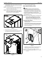
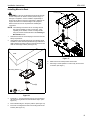
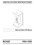
INSTALLATION INSTRUCTIONS
Instrucciones de instalación
Installationsanleitung
Instruções de Instalação
Istruzioni di installazione
Installatie-instructies
Instructions d´installation
Wall and Desk CPU Mount
Spanish Product Description
German Product Description
Portuguese Product Description
Italian Product Description
Dutch Product Description
French Product Description
KSA-1020
KSA-1020
Installation Instructions
DISCLAIMER
Milestone AV Technologies, and its affiliated corporations and
subsidiaries, (collectively, Milestone) intend to make this
manual accurate and complete. However, Milestone makes no
claim that the information contained herein covers all details,
conditions or variations, nor does it provide for every possible
contingency in connection with the installation or use of this
product. The information contained in this document is subject
to change without notice or obligation of any kind. Milestone
makes no representation of warranty, expressed or implied,
regarding the information contained herein. Milestone assumes
no responsibility for accuracy, completeness or sufficiency of
the information contained in this document.
Chief® is a registered trademark of Milestone AV Technologies.
All rights reserved.
IMPORTANT WARNINGS AND
CAUTIONS!
WARNING: A WARNING alerts you to the possibility of
serious injury or death if you do not follow the instructions.
WARNING: Failure to read, thoroughly understand, and
follow all instructions can result in serious personal injury,
damage to equipment, or voiding of factory warranty! It is the
installer’s responsibility to make sure all components are
properly assembled and installed using the instructions
provided.
WARNING: Failure to provide adequate structural strength
for this component can result in serious personal injury or
damage to equipment! It is the installer’s responsibility to
make sure the structure to which this component is attached
can support five times the combined weight of all equipment.
Reinforce the structure as required before installing the
component. The wall to which the mount is being attached
may have a maximum drywall thickness of 5/8" (1.6cm). Do
not install drywall anchors into the seam between drywall
pieces.
WARNING: Exceeding the weight capacity can result in
serious personal injury or damage to equipment! It is the
installer’s responsibility to make sure the combined weight of
all components attached to this accessory does not exceed
40 lbs (18.1 kg).
CAUTION: A CAUTION alerts you to the possibility of
damage or destruction of equipment if you do not follow the
corresponding instructions.
DIMENSIONS
360
SWIVEL
CAPABILITY
-UNDER DESK MOUNTED CONFIGURATION
*ONLY AVAILABLE WITH KSA-1020 PRODUCT
**OPTION NOT AVAILABLE WITH KWT110 ALL IN ONE WORKSTATION
37
1.46
MOUNTING SURFACE
TO CPU SURFACE
[0 - 191]
0" - 8.50"
WIDTH OF
CPU RANGE
[248 - 457]
CPU RANGE
2
7
.26
MOUNTING
HOLES
Installation Instructions
KSA-1020
LEGEND
Tighten Fastener
Pencil Mark
Apretar elemento de fijación
Marcar con lápiz
Befestigungsteil festziehen
Stiftmarkierung
Apertar fixador
Marcar com lápis
Serrare il fissaggio
Segno a matita
Bevestiging vastdraaien
Potloodmerkteken
Serrez les fixations
Marquage au crayon
Loosen Fastener
Drill Hole
Aflojar elemento de fijación
Perforar
Befestigungsteil lösen
Bohrloch
Desapertar fixador
Fazer furo
Allentare il fissaggio
Praticare un foro
Bevestiging losdraaien
Gat boren
Desserrez les fixations
Percez un trou
Phillips Screwdriver
Open-Ended Wrench
Destornillador Phillips
Llave de boca
Kreuzschlitzschraubendreher
Gabelschlüssel
Chave de fendas Phillips
Chave de bocas
Cacciavite a stella
Chiave a punte aperte
Kruiskopschroevendraaier
Steeksleutel
Tournevis à pointe cruciforme
Clé à fourche
TOOLS REQUIRED FOR INSTALLATION
7/64"
17/64"
1/2"
#2
1/2"
PARTS
B (2)
1/4-20"
A (1)
[CPU mount]
D (1)
[Swivel bearing]
C (4)
[Rubber edger--3"]
E (2)
1/4-20 x 1-3/4"
F (1)
3/8 x 1-1/4"
G (2)
#12 x 2-1/2"
3
KSA-1020
Installation Instructions
ASSEMBLY
3.
Installation of Protective Rubber Edging
If hanging mount underneath desk, remove mounting
buttons to reinstall them in the holes in which they will be
used.
1.
•
Place four strips of protective rubber edging (C) over the
sharp edges located on the top and bottom of the mount (A).
(See Figure 1)
•
(A)
If mounting vertically, move mounting buttons to
the four holes on top of the mount. (See Figure 3)
If mounting horizontally, move mounting buttons
to the top four holes on the back. (See Figure 3)
Vertical button location
Horizontal button location
1
(C) x 4
Figure 3
4.
Loosen adjustment knob at the back of the mounting unit
and adjust height of mount to a height greater than the
height of the CPU. Loosen strap at the front of the mount if
necessary. (See Figure 4)
Figure 1
CPU Installation
4
1.
Release bracket from mount by moving flag to open
position. (See Figure 2)
2.
Remove bracket from mounting buttons on back of mount.
(See Figure 2)
Strap
2
1
Latch closed
Latch open
Figure 2
4
Figure 4
Installation Instructions
5.
KSA-1020
Loosen adjustment knobs on top and bottom of the mount
and slide flanges in order to allow for the CPU to be inserted
for mounting. (See Figure 5)
8.
Tighten front strap to desired tension.
WALL MOUNT INSTALLATION
NOTE: Top and bottom knobs can be removed and inserted
into the front square holes in order to allow for large
CPU’s to be installed. (See Figure 5)
WARNING: FAILURE TO PROVIDE ADEQUATE
STRUCTURAL STRENGTH FOR THIS MOUNT CAN
RESULT IN SERIOUS PERSONAL INJURY OR DAMAGE
TO EQUIPMENT! It is the installer’s responsibility to make
sure the structure to which this mount is attached can support
five times the combined weight of the mount and all
equipment attached to it. Reinforce the structure as required
before installing the mount.
NOTE: Flanges may be reversed in order to allow for narrow
CPU’s to be installed in a secure manner. If this is
done, be sure to also remove and reinstall strap so that
the buckle is facing out for easy adjustment.
NOTE: Mount may be installed using 2" x 4" wood studs, steel
5
studs or it may be installed directly into drywall. For
steel stud and drywall installation, proceed to Site
Requirements for Using Steel Studs section. For
desk mounting, proceed to Installing to Desk section.
Installing to Wood Studs
5
1.
Determine location for mount keeping in mind CPU size and
safety requirements.
2.
Use the removed mounting bracket as a template and mark
through top and bottom holes of wall bracket. (See Figure 7)
3.
Drill two 7/64" diameter pilot holes at marked spots into
wood stud. (See Figure 7)
Figure 5
6.
Set CPU in CPU mount (A). (See Figure 6)
7.
Use adjustment knobs to compress mount around CPU until
CPU is tightly secured in mount (A). (See Figure 6)
2
(G) x 2
3
CPU
7
7
mounting bracket
Figure 7
4.
Install two #12 x 2-1/2" Phillips wood screws (G) through
bracket and drywall into wood stud. (See Figure 7)
5.
Ensure bracket is vertical, then tighten screws (G).
NOTE: Proceed to Mounting CPU to Wall section to complete
installation.
Figure 6
5
KSA-1020
Installation Instructions
Site Requirements for Using Steel Studs
WARNING: IMPROPER INSTALLATION CAN LEAD TO EQUIPMENT FALLING CAUSING SERIOUS PERSONAL INJURY
OR DAMAGE TO EQUIPMENT! The figure below identifies the minimum requirements for installation of display mounts onto a
steel stud structure. If the structure or its components do not meet these requirements contact the mount manufacturer for specific
instructions before attempting installation. It should also be noted that no other equipment should be mounted to the same stud.
16" or 24" (on center) Studs
Mount Installation Location
(Must be centered on stud)
If back side of wall is unfinished, drywall must be installed
to a minimum of one stud left and right of the stud(s)
being used to install the mount. Drywall must be
secured to studs with screws 12" on center
There must be a minimum of
1-7/8" (48mm) clearance
inside wall
FRONT
Drywall
**1/2"
minimum Drywall
Thickness
(Both Sides of Stud)
**See Hazard statement
on page 2!
Steel Stud (2 x 4 / 25ga minimum)
Stud type and structural strength must conform to the North American
Specification for the Design of Cold-Formed Steel Structural Members.
[362 S 125 18, C-Shaped, S-Stud Section]
Figure 8
6
Installation Instructions
KSA-1020
Installing to Steel Studs or Drywall
Steel Stud
Drywall
WARNING: IMPROPER INSTALLATION CAN LEAD TO
EQUIPMENT FALLING CAUSING SERIOUS PERSONAL
INJURY OR DAMAGE TO EQUIPMENT!
1.
Determine location for mount keeping in mind CPU size and
safety requirements.
2.
Use the removed mounting bracket as a template and mark
through top and bottom holes of wall bracket making sure
mounting holes are centered on stud. (See Figure 9)
3.
Drill two 1/2" diameter pilot holes at marked spots into wood
stud. (See Figure 9)
Plastic Cap
6
(B) x 2
5
Anchor Metal Channel
2
(Side View)
3
Figure 11
7.
8.
Snap off plastic straps on anchor at wall by pushing side to
side, snapping off straps level with flange of plastic cap.
(See Figure 12)
Repeat Steps 4 through 7 for remaining mounting hole.
Steel Stud
Drywall
7
Mounting holes centered on stud
Plastic Cap
Figure 9
4.
Hold metal channel on anchor (B) flat alongside plastic
straps and slide channel through hole. (See Figure 10)
Plastic Straps
Drywall
Plastic Straps
4
Anchor Metal Channel
(SIDE VIEW)
Figure 12
(B) x 2
Figure 10
5.
Holding plastic straps on anchor (B), pull anchor away from
wall until channel rests flush behind wall making sure anchor
channel is positioned vertically on stud. (See Figure 11)
6.
Slide plastic cap on anchor (B) towards wall until flange of
cap is flush with wall. (See Figure 11)
7
KSA-1020
Installation Instructions
9.
Place mounting bracket over anchors and align mounting
holes in mounting bracket with holes in anchors. (See
Figure 13)
10. Insert 1/4-20 x 1-3/4" Phillips pan head screw (E) into
mounting hole on mounting bracket and into anchor (B) and
tighten until flush against mounting bracket. DO NOT
overtighten! (See Figure 13)
11. Repeat Steps 9 and 10 for remaining mounting hole.
Steel Stud
2
Drywall
10
(E) x 2
Figure 14
3.
Move flag to closed position in order to fully secure mount
to bracket. (See Figure )
Mounting Bracket
Anchor Metal Channel
(SIDE VIEW)
Figure 13
Installing CPU Mount to Wall
CAUTION: Overtightening screws may cause wall bracket
to compress into soft wall surface resulting in difficult mount
installation.
1.
Ensure bracket flag is in the open position. (See Figure )
2.
Insert mounting buttons into the four large mounting holes
on the bracket and lower into place. (See Figure 14)
3
Latch closed
Latch open
(rear view)
Figure 15
8
Installation Instructions
KSA-1020
Installing Mount to Desk
(desk not shown)
Latching flag
WARNING: Failure to provide adequate structural strength
for this component can result in serious personal injury or
damage to equipment! It is the installer’s responsibility to
make sure the desk to which this component is attached can
support five times the combined weight of all equipment.
Reinforce the structure as required before installing the
component.
NOTE: The following instructions are for mounting with full
360° swivel capability for easy cord access. If this
capability is not desired, connect mounting bracket
using two screws as demonstrated in the Installing to
Wood Studs section.
1.
Determine location for mount keeping in mind CPU size and
safety requirements.
2.
Using bracket and swivel bearing (D) as a template, mark
and drill one 17/64" diameter pilot hole through underside of
desk at desired mounting location. Ensure entire mount will
clear the outer edge of desk. (See Figure 16)
5
Desk
Figure 17
2
6.
Slide buttons into locked position within holes.
7.
Move flag to closed position in order to fully secure mount
to bracket. (See Figure )
Mounting bracket
(D)
3
(F)
Figure 16
3.
Install 3/8 x 1-1/4" hex head lag screw (F) through bearing
(D) and mounting bracket into hole drilled in Step 2. (See
Figure 16)
4.
Ensure bracket flag is in the open position. (See Figure 15)
5.
Insert four mounting buttons into four mounting holes on the
bracket. (See Figure 17)
9
KSA-1020
10
Installation Instructions
Installation Instructions
KSA-1020
11
KSA-1020
Installation Instructions
USA/International
Europe
Chief Manufacturing, a products division of
Milestone AV Technologies
8834-002003 Rev00
2011 Milestone AV Technologies, a
Duchossois Group Company
www.chiefmfg.com
05/11
Asia Pacific
A
P
F
A
P
F
A
8401 Eagle Creek Parkway, Savage, MN 55378
800.582.6480 / 952.894.6280
877.894.6918 / 952.894.6918
Fellenoord 130 5611 ZB EINDHOVEN, The Netherlands
+31 (0)40 2668620
+31 (0)40 2668615
Office No. 1 on 12/F, Shatin Galleria
18-24 Shan Mei Street
Fotan, Shatin, Hong Kong
P 852 2145 4099
F 852 2145 4477