1
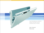
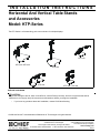
INSTALLATION INSTRUCTIONS
Horizontal And Vertical Table Stands
and Accessories
Model: KTP-Series
The KTP-Series is a free standing, pole mount solution for multiple displays.
KTP-320
KTP-220 / KTP-225
KTP-230
KTP-325
KTP-440 / KTP-445
BEFORE YOU BEGIN
CAUTION!
To prevent damage to the Kit, which could affect or void the Factory warranty, and to the equipment that will be
attached to it, thoroughly study all instructions and illustrations before you begin the installation.
•
If you have any questions about this installation, contact Chief Manufacturing.
Chief® and Centris™ are trademarks of Milestone AV Technologies. All rights reserved.
Chief Manufacturing, a products division
8832-000142 RevK
2010
Milestone
AV Technologies,
of Milestone AV Technologies
a Duchossois Group Company
8401 Eagle Creek Parkway, Savage, MN 55378
www.chiefmfg.com
• P: 800.582.6480 / 952.894.6280 • F:877.894.6918 / 952.894.6918
03/10
Model: KTP-Series
Installation Instructions
TOOLS REQUIRED FOR INSTALLATION
•
•
•
•
•
WEIGHT CAPACITIES
Phillips Head Screw Driver
3/4" Wrench
3/32" Hex Key (provided)
5/32" Hex Key (provided)
7/32" Hex Key (provided)
KTP-220 / KTP-225: 35 lbs. per monitor
KTP-230: 35 lbs. per monitor
KTP-320 / KTP-325: 30 lbs. per monitor
KTP-440 / KTP-445: 20 lbs. per monitor
PARTS
Carefully inspect components for shipping damage . If
damage is apparent, call your carrier claims agent and do
not continue with installation until the carrier has
reviewed the damage.(see Figure 1)
Table 1: Parts
QUANTITY By MODEL
ITEM DESCRIPTION
10
CENTRIS HEAD ASSEMBLY, Pole Mount
20
ARRAY ASSEMBLY, Dual, 27"
220
230
320
2
1
1
40
BASE, Freestand
1
1
50
POLE, Freestand, 14"
1
1
POLE, Freestand, 28"
POLE, Freestand, 42"
445
2
1
ARRAY ASSEMBLY, Triple, 54"
60
440
2
ARRAY ASSEMBLY, Triple, 42"
70*
325
1
ARRAY ASSEMBLY, Dual, 34"
30
225
1
1
2
1
2
1
1
1
1
1
80
SHEATH, Cable Management, 8"
1
1
2
1
2
2
2
90
SCREW, Freestand Pole Mounting, 3/8-16 x 1" (FHCS)
1
1
1
1
2
1
1
1
1
1
1
1
1
1
100*
SCREW, Cable Management Grommet Mounting, 3/8-16 x 6"
110*
GROMMET, Cable Management
120
KEY, Hex, 5/32"
130
KEY, Hex, 3/16"
140
KEY, Hex, 7/32"
160** SCREW, Phillips Pan Head, M4 x 12mm
1
1
1
1
1
1
1
1
8
8
8
12
12
16
16
170** SCREW, Phillips Pan Head, M4 x 20mm
8
8
8
12
12
16
16
180** SCREW, Phillips Pan Head, M4 x 30mm
8
8
8
12
12
16
16
190** SPACER, Nylon, 3/8" (used with item 170)
8
8
8
12
12
16
16
200** SPACER, Nylon, 3/4" (used with item 180)
8
8
8
12
12
16
16
1
2
2
2
210
CLAMP, Front, Pole Mount
2
220
CLAMP, Rear, Pole Mount
2
230
SCREW, Button Head Cap,
240
CLAMP, Back, Array mounting
6
1
1
250
WASHER, Flat, 1/4"
2
2
2
4
4
4
260
SCREW, Button Head Cap, 1/4-20 x 3/4"
2
2
2
4
4
4
270
PIPE CAP, 1.75 OD
1
1
1
2
1
1
1
* Indicates an available optional accessory not included with above models. For additional information pertaining to available
accessories contact a Chief Customer Service representative or visit us at www.chiefmfg.com.
** Quantity varies depending upon the number of displays being installed.
2
Installation Instructions
Model: KTP-Series
(160)
(10 Includes 210, 220, 230)
(180) (200)
(120)
(190)
(20)
(170)
(130)
(140)
250
260
(30)
(110)
(100)
270
(80)
240
(40)
(90)
(50)
(70)
(60)
Figure 1: Parts
ASSEMBLY AND INSTALLATION
(210)
Mount Assembly
(60)
KTP-230 Assembly
To assemble the KTP-230:
(220)
1. Assemble pole (60) to base (40) using one 3/8-16 x 1"
FHCS (90). (see Figure 2)
(60)
(140)
(90)
(40)
(230)
Figure 3: Mount Centris Head with Pole Clamp
NOTE: Equally tighten screws (230) against front pole
mount (210) and rear (220) pole clamps. (see
Figure 4)
Figure 2: Assemble Pole to Base
2. Place front pole clamp, with Centris Head, (210)
against pole in approximate mounting location.
3. Place three BHCS (230) into rear pole clamp (220)
and place against pole aligning with front pole clamp
(210). (see Figure 3)
3
Model: KTP-Series
Installation Instructions
Display Installation
Attach Centris Head to Flush Mount Display
(230)
Keep equal
distance between
mount and
clamp when
tightening
(220)
(210)
CAUTION!
CAUTION: If display uses a screw size other than
those included in the kit, DO NOT use the screws
provided. Using the wrong screws could result in
damage to your monitor.
1. Install two M4 x 12mm Phillips pan head screws (160)
into two upper mounting holes in display back.
(see Figure 6)
NOTE: DO NOT fully tighten at this time.
Figure 4:
2. Hang display on Centris head. (see Figure 7)
4. Secure rear pole clamp (220) to front pole mount
(210) and pole by tightening three BHCS (230) using
5/32" hex key (120). (see Figure 3)
5. Add pipe cap (270) to top of pole.
3. Install bottom two M4 x 12mm Phillips pan head
screws (160) through Centris head mounting holes
and into lower mounting holes in display back.
4. Tighten ALL four M4 x 12mm Phillips pan head
screws (160). (see Figure 8)
KTP-220, 320, and 440 Assembly
To assemble the KTP-220, 320, and 440:
1. Assemble pole (50) to base (40) using one 3/8-16 x 1"
FHCS (90). (see Figure 2)
M4 x 12mm Phillips Pan Head Screw (30)
2. Assemble pole clamp back (240) to pole mount front
using two FW (250) and two BHCS (260) using a
5/32" hex key. (see Figure 5)
3. Secure pole mount back (240) to pole mount front and
pole by tightening two BHCS (260) using a 5/32" hex
key.
Pole
Display
Pole Mount front
with Array
Figure 6: Prepare Display
(250)
Display
(260)
Pole Clamp Back (240)
Figure 5: Assemble Array Rail to Pole
4. Add pipe cap (270) to top of pole.
4
(20, 30)
Centris Head
Figure 7: Hang Display
Installation Instructions
Model: KTP-Series
3. Place display face down on a clean dry surface.
Display
Centris Head
4. Place four 3/8" or 3/4" nylon spacers (190 or 200)
over four mounting holes in display back (see Figure
11).
5. Align Centris head mounting holes with four nylon
spacers (see Figure 11).
6. Secure Centris head to display using four
M4 x 20mm Phillips pan head screws (170), or four
M4 x 30mm Phillips pan head screws (180)
(see Figure 11).
(20, 30)
Phillips Pan Head Screw
(170 or 180)
(160)
Centris Head
Figure 8: Secure Display to Centris Bracket
Attach Centris Head to Recessed Mount Display
Spacer
(190 or 200)
NOTE: Refer to Table 3 to select the applicable screw
and spacer combination.
1. Uninstall end lock using the 5/32" hex key (120).
(see Figure 9)
2. Remove Centris head from array rail (20, 30).
Centris Head
Display
Square Nut
Figure 11: Mount Centris Bracket to Display
7. Slide display with Centris bracket onto array rail (20,
30) (see Figure 12).
NOTE: Repeat previous steps for each additional display.
End Lock
(20, 30)
8. Reinstall end locks into mounting rail using the 5/32"
hex key (120) (see Figure 13).
Figure 9: Remove End Lock(s)
Display with Centris Bracket
(20, 30)
Centris Head
Figure 10: Slide Centris Bracket off Array Rail
(20, 30)
Figure 12: Mount Display with Centris Bracket to
Array Rail
5
Model: KTP-Series
Installation Instructions
Display Pitch and Roll Adjustment
To adjust display pitch or roll position:
(20, 30)
1. Loosen Centris bracket front adjustment knob.
(see Figure 15)
End Lock
2. Tilt display up or down, or adjust display roll left or
right until properly positioned.
3. Tighten Centris bracket front adjustmnent knob.
End Lock Retaining Screw
Pitch/Roll
Adjustment
Knob
Centris Head
Figure 13: Reinstall End Lock(s)
ADJUSTMENTS
Display Adjustment
The KTP Series mount allows horizontal, pitch, and
rotational adjustment of each display.
The KTP Series mount also allows a full 360 deg. of
display rotation with a maximum pitch range of 15° up
and 15° down.
Display Horizontal Position Adjustment
Figure 15: Display Pitch and Roll Adjustment
CABLE MANAGEMENT
To adjust display horizontal position:
1. Loosen Centris bracket rear adjustment knob (see
Figure 14).
2. Slide Centris bracket with display left or right until
properly positioned on array rail.
3. Tighten Centris bracket rear adjustmnent knob.
The KTP Series mount includes cable management
features used to properly route and secure display
cables.
To use the cable management features:
1. Connect cables to display.
2. Route cables through cable clips on array rail.
3. Route cables down pole and away from mount and
secure to pole using sheath (80).
Horizontal
Adjustment
Knob
Cable Clips
(80)
Figure 14: Display Horizontal Adjustment
6
Figure 16: Cable Management
Installation Instructions
Model: KTP-Series
7
Model: KTP-Series
8
Installation Instructions