1
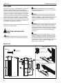
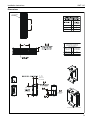
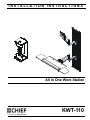
INSTALLATION INSTRUCTIONS
Instrucciones de instalación
Installationsanleitung
Instruções de Instalação
Istruzioni di installazione
Installatie-instructies
Instructions d´installation
All in One Work Station
Spanish Product Description
German Product Description
Portuguese Product Description
Italian Product Description
Dutch Product Description
French Product Description
KWT-110
KWT-110
Installation Instructions
DISCLAIMER
CAUTION: A CAUTION alerts you to the possibility of
damage or destruction of equipment if you do not follow the
corresponding instructions.
Milestone AV Technologies, and its affiliated corporations and
subsidiaries, (collectively, Milestone) intend to make this
manual accurate and complete. However, Milestone makes no
claim that the information contained herein covers all details,
conditions or variations, nor does it provide for every possible
contingency in connection with the installation or use of this
product. The information contained in this document is subject
to change without notice or obligation of any kind. Milestone
makes no representation of warranty, expressed or implied,
regarding the information contained herein. Milestone assumes
no responsibility for accuracy, completeness or sufficiency of
the information contained in this document.
WARNING: Failure to read, thoroughly understand, and
follow all instructions can result in serious personal injury,
damage to equipment, or voiding of factory warranty! It is the
installer’s responsibility to make sure all components are
properly assembled and installed using the instructions
provided.
WARNING: Failure to provide adequate structural strength
for this component can result in serious personal injury or
damage to equipment! It is the installer’s responsibility to
make sure the structure to which this component is attached
can support five times the combined weight of all equipment.
Reinforce the structure as required before installing the
component.
Chief® and Centris® are registered trademarks of Milestone AV
Technologies. All rights reserved.
IMPORTANT WARNINGS AND
CAUTIONS!
WARNING: Exceeding the weight capacity can result in
serious personal injury or damage to equipment! It is the
installer’s responsibility to make sure the combined weight of
all components attached to the CPU wall mount does not
exceed 40 lbs (18.1 kg). The maximum weight of the monitor
mount is 25 lbs (11.3 kg). The maximum weight of the
keyboard tray is 10 lbs (4.5 kg).
WARNING: A WARNING alerts you to the possibility of
serious injury or death if you do not follow the instructions.
Dimensions
VERTICAL INSTALLATION
CABLE
MANAGEMENT
CHANNELS
240
9.47
CPU WALL MOUNT
MAX WEIGHT: 40LBS.
15
.60 DEPTH FROM WALL
TO ACCESSORY
MOUNTING SURFACE
22
.88
13
.50
MONITOR MOUNT
MAX WEIGHT: 25LBS.
176
6.91
254
10.00
114
4.50
406
16.00
KEYBOARD TRAY
MAX WEIGHT: 10LBS.
HORIZONTAL INSTALLATION
6
.25 TYP.
HOLE SIZE
918
36.15
FLEXIBLE/REMOVEABLE
CABLE MANAGEMENT
COVERS
2
508
20.00
813
32.00
Installation Instructions
KWT-110
Dimensions
COMPONENT
MOUNTING
BRACKET
OPTIONS
"X"
DRYWALL
MINIMUM DISTANCE BETWEEN
COMPONENT MOUNTING
BRACKETS IN HORIZONTAL
CONFIGURATION
INSTALLATION
OPTIONS
X
AVAILABLE
ADJUSTMENT
STEEL STUD
8"
23"
WOOD STUD
BRACKET
0 191
0" 7.50"
WIDTH OF
CPU RANGE
[248] [457]
CPU RANGE
7
.26
MOUNTING
HOLES
SHOWN WITH CPU INSTALLED
3
KWT-110
Installation Instructions
DIMENSIONS
90
60
2.36
RETRACTED
PIVOT 180
19.45
LIFT ARM
13.25" VERTICAL RANGE
41
1.63
[254]
10.0
VESA STANDARD
75mm 100mm
165
6.50
33
1.30
268
10.57
143
5.63
144
5.67
61
2.40
5.99 KEYBOARD DEPTH
6.50
SWING OUT
MOUSE TRAY
KEYBOARD TRAY
180 PIVOT POINTS
18.75
EXTENDED
COLLAPSED
1.30
6.50
10.02
WRIST PAD
(REMOVABLE FOR
DEEPER KEYBOARDS)
SWING OUT
MOUSE TRAY
6.50
7.73 6.50
DISTANCE TO THE
CENTER OF THE
COMPONENT
MOUNTING BRACKET
4
MAX 29.15
3.33 COLLAPSED
Installation Instructions
KWT-110
LEGEND
Tighten Fastener
Pencil Mark
Apretar elemento de fijación
Marcar con lápiz
Befestigungsteil festziehen
Stiftmarkierung
Apertar fixador
Marcar com lápis
Serrare il fissaggio
Segno a matita
Bevestiging vastdraaien
Potloodmerkteken
Serrez les fixations
Marquage au crayon
Loosen Fastener
Drill Hole
Aflojar elemento de fijación
Perforar
Befestigungsteil lösen
Bohrloch
Desapertar fixador
Fazer furo
Allentare il fissaggio
Praticare un foro
Bevestiging losdraaien
Gat boren
Desserrez les fixations
Percez un trou
Phillips Screwdriver
Adjust
Destornillador Phillips
Ajustar
Kreuzschlitzschraubendreher
Einstellen
Chave de fendas Phillips
Ajustar
Cacciavite a stella
Regolare
Kruiskopschroevendraaier
Afstellen
Tournevis à pointe cruciforme
Ajuster
Open-Ended Wrench
Remove
Llave de boca
Quitar
Gabelschlüssel
Entfernen
Chave de bocas
Remover
Chiave a punte aperte
Rimuovere
Steeksleutel
Verwijderen
Clé à fourche
Retirez
By Hand
Optional
A mano
Opcional
Von Hand
Optional
Com a mão
Opcional
A mano
Opzionale
Met de hand
Optie
À la main
En option
Hex-Head Wrench
Security Wrench
Llave de cabeza hexagonal
Llave de seguridad
Sechskantschlüssel
Sicherheitsschlüssel
Chave de cabeça sextavada
Chave de segurança
Chiave esagonale
Chiave di sicurezza
Zeskantsleutel
Veiligheidssleutel
Clé à tête hexagonale
Clé de sécurité
5
KWT-110
Installation Instructions
TOOLS REQUIRED FOR INSTALLATION
1/4"(included)
1/8"(included)
3/16"(included)
5/32"(included)
7/64"
17/64"
1/2"
#2
PARTS
A(1)
B(1)
C(1)
G(1)
E(4)
F(1)
D(1)
H(2)
6
J(4)
K(8)
L(2)
Installation Instructions
KWT-110
PARTS - CONTINUED
M(6)
P(4)
1/2 x .194 x 3/4"
N(6)
#10
S(4)
M4 x 12
T(4)
M4 x 20
Y(1)
1/4"
Z(1)
3/16"
R(6)
#12 x 2 1/2"
Q(4)
1/2 x .194 x 3/8"
U(4)
M4 x 30
AA(1)
5/32"
V(6)
W(4)
#10-24 x 1/2"
#8-32 x 3/8"
X(8)
1/4-20 x 1 3/4"
BB(1)
1/8"
7
KWT-110
Installation Instructions
ASSEMBLY AND INSTALLATION - CPU
MOUNT
3.
Loosen adjustment knob at the back of the mounting unit
and adjust height of mount to a height greater than the
height of the CPU to be installed. Loosen strap at the front
of the mount if necessary. (See Figure 3)
Installation of Protective Rubber Edging
1.
Place four strips of protective rubber edging (E) over the
sharp edges located on the top and bottom of the CPU
mount (D). (See Figure 1)
3
(D)
1
(E) x 4
Figure 3
4.
Loosen adjustment knobs on top and bottom of the mount
and slide flanges in order to allow for the CPU to be inserted
for mounting. (See Figure 4)
Figure 1
NOTE: Top and bottom knobs can be removed and inserted
CPU Installation
1.
Release bracket from mount by moving the flag to the open
position. (See Figure 2)
2.
Remove bracket from mounting buttons on back of mount.
(See Figure 2)
into the front square holes in order to allow for large
CPU’s to be installed. (See Figure 4)
NOTE: Flanges may be reversed in order to allow for narrow
CPU’s to be installed in a secure manner. If this is
done, be sure to also to remove and reinstall strap so
that the buckle is facing out for easy adjustment.
4
2
1
Figure 4
Figure 2
8
5.
Set CPU within mount (D). (See Figure 5)
Installation Instructions
6.
KWT-110
Use adjustment knobs to compress mount around CPU until
CPU is tightly secured within mount (D). (See Figure 5)
3
6
(R) x 2
2
6
mounting bracket
Figure 6
Figure 5
3.
Install two #12 x 2 1/2" round Phillips wood screws (R)
through bracket and drywall into wood stud. (See Figure 6)
4.
Ensure bracket is vertical, then tighten screws (R).
NOTE: Proceed ahead to Mounting CPU to Wall section to
complete installation.
7.
Tighten front strap to desired tension.
CPU WALL MOUNT INSTALLATION
WARNING: FAILURE TO PROVIDE ADEQUATE
STRUCTURAL STRENGTH FOR THIS MOUNT CAN
RESULT IN SERIOUS PERSONAL INJURY OR DAMAGE
TO EQUIPMENT! It is the installer’s responsibility to make
sure the structure to which this mount is attached can support
five times the combined weight of the mount and all
equipment attached to it. Reinforce the structure as required
before installing the mount.
NOTE: Mount may be installed using wood studs, steel studs
or it may be installed directly into drywall. For steel stud
and drywall installation, proceed ahead to Site
Requirements for Using Steel Studs section. For desk
mounting, proceed ahead to Desk Mounting
Installation section.
CPU Mount Installation Using Wood Studs
1.
Determine location for mount keeping in mind CPU size and
safety requirements.
2.
Using the removed mounting bracket as a template, mark
and then drill two 7/64" diameter pilot holes through top and
bottom holes of wall bracket into wall. (See Figure 6)
9
KWT-110
Installation Instructions
Site Requirements for Using Steel Studs
WARNING: IMPROPER INSTALLATION CAN LEAD TO EQUIPMENT FALLING CAUSING SERIOUS PERSONAL INJURY
OR DAMAGE TO EQUIPMENT! The figure below identifies the minimum requirements for installation of display mounts onto a
steel stud structure. If the structure or its components do not meet these requirements contact the mount manufacturer for specific
instructions before attempting installation. It should also be noted that no other equipment should be mounted to the same stud.
16", 20" or 24" (on center) Studs
Mount Installation Location
(Must be centered on stud)
If back side of wall is unfinished, drywall must be installed
to a minimum of one stud left and right of the stud(s)
being used to install the mount. Drywall must be
secured to studs with screws 12" on center
There must be a minimum of
1 7/8" (48mm) clearance
inside wall
FRONT
Drywall
**1/2"
minimum Drywall
Thickness
(Both Sides of Stud)
**See Hazard statement
on page 2!
Steel Stud (2 x 4 / 25ga minimum)
Stud type and structural strength must conform to the North American
Specification for the Design of Cold-Formed Steel Structural Members.
[362 S 125 18, C-Shaped, S-Stud Section]
Figure 7
10
Installation Instructions
KWT-110
Wall Mounting Using Steel Studs or Drywall
After determining the site meets the installation requirements:
Steel Stud
1.
2.
3.
Drywall
Identify desired mounting location on wall.
Using a stud finder or similar method locate stud.
Align mounting holes in mount with stud making sure
mounting holes are centered on stud. (See Figure 8)
Plastic Cap
WARNING: IMPROPER INSTALLATION CAN LEAD TO
EQUIPMENT FALLING CAUSING SERIOUS PERSONAL
INJURY OR DAMAGE TO EQUIPMENT!
4.
5.
8
Mark location of two mounting holes on wall using the wall
plate as a template. Mark holes where the top and bottom
holes of the bracket will be connected. (See Figure 8)
(K) x 2
7
Anchor Metal Channel
Drill two 1/2" holes. (See Figure 8)
(Side View)
Figure 10
5
4
9.
Snap off plastic straps on anchor at wall by pushing side to
side, snapping off straps level with flange of plastic cap.
(See Figure 11)
10. Repeat steps 6 through 9 for remaining mounting hole.
1/2"x2
Steel Stud
Drywall
9
Plastic Cap
Mounting holes centered on stud
Figure 8
6.
Hold metal channel on anchor (K) flat alongside plastic
straps and slide channel through hole. (See Figure 9)
Plastic Straps
Anchor Metal Channel
Drywall
Plastic Straps
6
(SIDE VIEW)
Figure 11
(K) x 2
Figure 9
7.
8.
Holding plastic straps on anchor (K), pull anchor away from
wall until channel rests flush behind wall making sure
anchor channel is positioned vertically on stud. (See Figure
10)
11. Place mounting bracket over anchors and align mounting
holes in display mount with holes in anchors. (See Figure
12)
12. Insert 1/4-20 x 1-3/4" Phillips pan head screw (X) into
mounting hole on mounting bracket and into anchor (K) and
tighten until flush against mounting bracket. DO NOT
overtighten! (See Figure 12)
13. Repeat steps 11 through 13 for remaining mounting hole.
Slide plastic cap on anchor (K) towards wall until flange of
cap is flush with wall. (See Figure 10)
11
KWT-110
Installation Instructions
Steel Stud
Drywall
12
(X) x 2
13
3
(Flag in closed position)
Mounting Bracket
Anchor Metal Channel
Figure 14
(SIDE VIEW)
WALL TRACK INSTALLATION
Figure 12
Mounting CPU to Wall
1.
Determine mounting location on wall.
2.
Determine whether wall track accessory will be mounted
horizontally or vertically.
CAUTION: Overtightening screws may cause wall bracket
to compress into soft wall surface resulting in difficult mount
installation.
WARNING: The KSA-1022 wall track accessory CANNOT
be installed horizontally on drywall without wood or steel
studs.
1.
Ensure bracket flag is in the open position. (See Figure 2)
Vertical Installation using Wood Studs
2.
Insert mounting buttons into the four large mounting holes
on the bracket. (See Figure 13)
1.
Using a stud finder or similar method locate stud.
2.
Align the middle mounting holes on mount with stud making
sure mounting holes are centered on stud. (See Figure 15)
3.
Using wall track accessory (A) as a template, mark location
of three mounting holes on wall. (See Figure 15)
2
Figure 13
3.
12
Move flag to closed position in order to fully secure mount
to bracket. (See Figure 14)
Installation Instructions
(A)
KWT-110
3
X3
4
X3
5
(R) x 3
(A)
Mounting holes
centered on stud
Figure 16
Figure 15
4.
Drill three 7/64" holes. (See Figure 15)
5.
Install three #12 x 2 1/2" round pan wood screws (R)
through small center bracket holes and into drilled holes.
(See Figure 16)
Vertical Installation on Drywall
WARNING: Drywall must be at least 1/2" thick in order to
install wall track accessory.
1.
Using wall track accessory (A) as a template, mark location
of six mounting holes on wall making sure it will be level.
(See Figure 17)
1
X6
2
X6
(A)
Figure 17
13
KWT-110
Installation Instructions
2.
Drill six 1/2" holes at locations marked in Step 1. (See
Figure 18)
3.
Hold metal channel on anchor (K) flat alongside plastic
straps and slide channel through hole. (See Figure 18)
Drywall
6
Plastic Cap
Drywall
Plastic Straps
3
Plastic Straps
(K) x 6
Anchor Metal Channel
Figure 18
4.
Holding plastic straps on anchor (K), pull anchor away from
wall until channel rests flush behind wall making sure
anchor channel is positioned vertically on stud. (See Figure
19)
5.
Slide plastic cap on anchor (K) towards wall until flange of
cap is flush with wall. (See Figure 19)
Drywall
SIDE VIEW
Figure 20
8.
Place wall track accessory (A) over anchors and align
mounting holes in display mount with holes in anchors. (See
Figure 21)
9.
Insert 1/4-20 x 1 3/4" Phillips pan head screws (X) through
corresponding mounting hole on wall track accessory (A)
and into anchor (K) and tighten until flush against mount.
DO NOT overtighten! (See Figure 21)
10. Repeat steps 8 through 9 for remaining 5 mounting holes.
Plastic Cap
Drywall
5
(K) x 6
Anchor Metal Channel
9
(X) x 6
SIDE VIEW
Figure 19
6.
7.
Snap off plastic straps on anchor at wall by pushing side to
side, snapping off straps level with flange of plastic cap.
(See Figure 20)
Repeat steps 3 through 6 for each mounting hole.
(A)
Anchor Metal Channel
SIDE VIEW
Figure 21
14
Installation Instructions
KWT-110
Horizontal Installation using Wood Studs
NOTE: Wall track accessory may be mounted horizontally to
two studs that are 16", 20" or 24" apart.
1.
Use a stud finder or similar method to determine location of
studs.
2.
Draw a vertical line down the center of the studs to be used.
(See Figure 22)
3.
Using wall track accessory (A) as a template, mark location
of mounting holes on wall. Make sure wall track accessory
is level. (See Figure 22)
WARNING: Only long holes may be used to mount device
on dual studs. DO NOT mount device using the small holes
unless mounting on three studs.
studs
(A)
5
(R) x 4
Figure 23
(A)
2
3
Figure 22
4.
Drill 7/64" holes at each marked location. (See Figure 22)
5.
Install four #12 x 2 1/2" round pan wood screws (R) through
wall accessory holes into the holes drilled in Step 4. (See
Figure 23)
15
KWT-110
Installation Instructions
Site Requirements for Steel Studs
WARNING: IMPROPER INSTALLATION CAN LEAD TO EQUIPMENT FALLING CAUSING SERIOUS PERSONAL INJURY
OR DAMAGE TO EQUIPMENT! The figure below identifies the minimum reguirements for installation of display mounts onto a
steel stud structure. If the structure or its components do not meet these requirements contact the mount manufacturer for specific
instructions before attempting installation. It should also be noted that no other equipment should be mounted to the same stud.
16", 20" or 24" Studs may be used for Single or Dual Studs (shown)
(Must be centered on stud)
If back side of wall is unfinished, drywall must be installed
to a minimum of one stud left and right of the stud(s)
being used to install the mount. Drywall must be
secured to studs with screws 12" on center
There must be a minimum of
1 7/8" (48mm) clearance
inside wall
FRONT
Drywall
**1/2" (100 lbs max) or
minimum
Drywall Thickness
(Both Sides of Stud)
*See hazard statement
on page 2!
Steel Stud (2 x 4 / 25ga minimum)
Stud type and structural strength must conform to the North American
Specification for the Design of Cold-Formed Steel Structural Members.
[362 S 125 18, C-Shaped, S-Stud Section]
16
Installation Instructions
KWT-110
Vertical Installation using Steel Studs
8.
Slide plastic cap on anchor (K) towards wall until flange of
cap is flush with wall. (See Figure 26)
After determining the site meets the installation requirements:
1.
Identify desired mounting location on wall.
2.
Using a stud finder or similar method locate stud.
3.
Align the middle mounting holes on mount with stud making
sure mounting holes are centered on stud. (See Figure 24)
4.
Using wall track accessory (A) as a template, mark location
of three mounting holes on wall. (See Figure 24)
Steel Stud
3
Drywall
Plastic Cap
X3
8
(K) x 3
4
(A)
X3
Anchor Metal Channel
SIDE VIEW
Figure 26
9.
Snap off plastic straps on anchor at wall by pushing side to
side, snapping off straps level with flange of plastic cap.
(See Figure 27)
10. Repeat steps 6 through 9 for each mounting hole.
Steel Stud
Drywall
9
Plastic Cap
Mounting holes
centered on stud
Plastic Straps
Figure 24
5.
Drill three 1/2" holes in locations marked in Step 4.
6.
Hold metal channel on anchor (K) flat alongside plastic
straps and slide channel through hole. (See Figure 25)
Anchor Metal Channel
SIDE VIEW
Drywall
Plastic Straps
6
Figure 27
11. Place wall track accessory (A) over anchors and align
mounting holes in display mount with holes in anchors. (See
Figure 27)
12. Insert 1/4-20 x 1 3/4" Phillips pan head screws (X) through
corresponding mounting hole on wall track accessory and
into anchor (K) and tighten until flush against mount. DO
NOT overtighten! (See Figure 28)
(K) x 3
Figure 25
7.
13. Repeat steps 11 through 12 for remaining 2 mounting holes.
Holding plastic straps on anchor (K), pull anchor away from
wall until channel rests flush behind wall making sure
anchor channel is positioned vertically on stud. (See Figure
26)
17
KWT-110
Installation Instructions
WARNING: IMPROPER INSTALLATION CAN LEAD TO
EQUIPMENT FALLING CAUSING SERIOUS PERSONAL
INJURY OR DAMAGE TO EQUIPMENT! Overtightening of
mounting hardware can damage the steel studs. DO NOT
overtighten mounting hardware!
Steel Stud
Drywall
9
(X) x 3
(A)
4
x4
5
(A)
Anchor Metal Channel
Figure 29
SIDE VIEW
6.
Figure 28
Hold metal channel on anchor (K) flat alongside plastic
straps and slide channel through hole. (See Figure 30)
Drywall
Horizontal Installation Using Steel Studs
Plastic Straps
NOTE: Wall track accessory may be mounted horizontally to
6
two studs that are 16", 20" or 24" apart.
After determining the site meets the installation requirements:
1.
Identify desired mounting location on wall.
2.
Use a stud finder or similar method to determine location of
studs.
3.
Draw a vertical line down the center of the studs to be used.
(See Figure 29)
4.
Using wall track accessory (A) as a template, mark location
of three mounting holes on wall. Make sure wall track
accessory is level. (See Figure 29)
WARNING: Only long holes may be used to mount device
on dual studs. DO NOT mount device using the small holes!
5.
18
Drill 1/2" holes at each marked location. (See Figure 29)
(K) x 4
Figure 30
7.
Holding plastic straps on anchor (K), pull anchor away from
wall until channel rests flush behind wall making sure
anchor channel is positioned vertically on stud. (See Figure
31)
8.
Slide plastic cap on anchor (K) towards wall until flange of
cap is flush with wall. (See Figure 31)
Installation Instructions
KWT-110
Steel Stud
Steel Stud
Drywall
Drywall
Plastic Cap
9
(D) x 4 or 6
8
(K) x 4
Anchor Metal Channel
SIDE VIEW
(A)
Figure 31
Anchor Metal Channel
9.
Snap off plastic straps on anchor at wall by pushing side to
side, snapping off straps level with flange of plastic cap.
(See Figure 32)
10. Repeat steps 6 through 9 for each mounting hole.
Steel Stud
Drywall
9
SIDE VIEW
Figure 33
Mount Installation on Horizontal Bracket
WARNING: Exceeding the weight capacity can result in
Plastic Cap
serious personal injury or damage to equipment! It is the
installer’s responsibility to make sure the weight of each
component attached to the KSA-1022 wall track accessory
does not exceed 25 lbs (11.3 kg) or the specific weight limit
for the attached mounting device.
WARNING: For horizontal mounting on wood or steel
Plastic Straps
studs, a minimum distance of 8" must exist between mounted
devices. (See Figure 34)
Anchor Metal Channel
SIDE VIEW
8" minimum
Figure 32
11. Place wall track accessory (A) over anchors and align
mounting holes in display mount with holes in anchors. (See
Figure 33)
12. Insert 1/4-20 x 1 3/4" Phillips pan head screws (D) through
corresponding mounting hole on wall track accessory and
into anchor (C) and tighten until flush against mount. DO
NOT overtighten! (See Figure 33)
13. Repeat steps 11 through 12 for remaining mounting holes.
Figure 34
WARNING: IMPROPER INSTALLATION CAN LEAD TO
1.
EQUIPMENT FALLING CAUSING SERIOUS PERSONAL
INJURY OR DAMAGE TO EQUIPMENT! Overtightening of
mounting hardware can damage the steel studs. DO NOT
overtighten mounting hardware!
Remove side cover to slide locking plate brackets (J) into
wall track accessory (A) at the desired mounting location.
(See Figure 35)
NOTE: Locking plate brackets must be inserted into the top
channel and second channel from the bottom.
19
KWT-110
Installation Instructions
(J) x 2
1
(H)
(N) x 2
3
(V) x 2
2
Figure 35
2.
Reinstall side cover to wall track accessory after locking
plate brackets have been inserted. (See Figure 35)
3.
Use 1/8" hex key (BB) to install #10 button head cap screws
(V) through #10 washers (N) and wall plate (H) into center
holes of locking plate brackets (J). (See Figure 35)
4.
Ensure wall plate (H) is vertical, then tighten screws (V).
(See Figure 35)
(B)
(H)
(A)
WARNING: Overtightening screws may cause wall bracket
to compress into wall track accessory surface, resulting in
difficult mount installation or improper engaging of set screw
in later step.
5.
Insert top of Centris display mount (B) over lip on top of wall
plate (H) on preferred location. (See Figure 36)
6.
Swing Centris display mount (B) down flush against wall
track accessory (A). (See Figure 36)
Figure 36
20
Installation Instructions
KWT-110
Mount Installation on Vertical Bracket
7.
WARNING: Exceeding the weight capacity can result in
Use 5/32" hex driver (AA) to tighten set screw in bottom of
wall mount. (See Figure 37)
serious personal injury or damage to equipment! It is the
installer’s responsibility to make sure the weight of each
component attached to the KSA-1022 wall track accessory
does not exceed 25 lbs (11.3 kg) or the specific weight limit
for the attached mounting device.
NOTE: Ensure set screw engages on back side of wall plate to
properly secure wall mount.
(B or C)
WARNING: For vertical mounting on wood or steel studs, a
minimum distance of 8" must exist between mounted
devices. For vertical mounting on drywall, a minimum
distance of 16" must exist between mounted devices. (See
Figure 39)
7
Set
Screw
Drywall
Wood or Steel Studs
Figure 37
8.
Insert top of keyboard tray mount (C) over lip on top of the
other wall plate (H). (See Figure 38)
9.
Swing keyboard tray mount (C) down flush against wall.
(See Figure 38)
8"
minimum
16"
min
(C)
(H)
(A)
Figure 39
1.
Remove side cover to slide locking plate brackets (J) into
wall track accessory (A) at the desired mounting location.
(See Figure 40)
NOTE: Locking plate brackets must be inserted into center
channel on wall track accessory.
2.
Reinstall side cover to wall track accessory after all locking
plate brackets have been inserted. (See Figure 40)
Figure 38
10. Use 5/32" hex driver (AA) to tighten set screw in bottom of
wall mount. (See Figure 37)
NOTE: Ensure set screw engages on back side of wall plate to
properly secure wall mount.
21
KWT-110
Installation Instructions
9.
Swing keyboard tray mount (C) down flush against wall.
(See Figure 38)
10. Use 5/32" hex driver (AA) to tighten set screw in bottom of
wall mount. (See Figure 37)
1
NOTE: Ensure set screw engages on back side of wall plate to
properly secure wall mount.
2
Keyboard and Wrist Pad Installation
1.
Remove adhesive backing from one side of hook and loop
connectors (M).
2.
Place hook and loop connectors (M) on bottom of the
keyboard and bottom of wrist pad (F) approximately as
shown. (See Figure 41)
NOTE: Place connectors only on flat sections of the keyboard
to ensure that they stick to the surface.
(J)
(H)
((B)
3.
Remove the adhesive backing from the other side of the
hook and loop connectors (M).
4.
Firmly place keyboard on keyboard tray making sure to
leave room for the wrist pad if necessary. (See Figure 41)
5.
Firmly place wrist pad (F) on keyboard tray in front of the
keyboard. (See Figure 41)
(N) x 2
keyboard
(M) x 6
3
(V) x 2
(F)
Figure 40
3.
Use 1/8" hex key (BB) to install #10 button head cap screws
(V) through #10 washers (N) and wall plate (H) into center
holes of locking plate brackets (J). (See Figure 40)
(C)
NOTE: Wall brackets must be secured by installing screws
through the top and bottom holes of the wall plate (H).
(See Figure 40)
4.
Figure 41
Ensure wall plate (H) is vertical, then tighten screws (V).
Mouse Holder Installation
CAUTION: Overtightening screws may cause wall bracket
to compress into wall track accessory surface, resulting in
difficult mount installation or improper engaging of set screw
in later step.
5.
Insert top of Centris display mount (B) over lip on top of wall
plate (H) on preferred location. (See Figure 36)
6.
Swing Centris display mount (B) down flush against wall
track accessory (A). (See Figure 36)
7.
Use 5/32" hex driver (AA) to tighten set screw in bottom of
wall mount. (See Figure 37)
NOTE: Ensure set screw engages on back side of wall plate to
properly secure wall mount.
8.
22
Insert top of keyboard tray mount (C) over lip on top of the
other wall plate (H). (See Figure 38)
1.
Remove adhesive backing from mouse holder (G).
2.
Place mouse holder (G) on wall at desired location. (See
Figure 41)
Installation Instructions
KWT-110
Cable Management
Bracket (in open position)
(G)
Cable Path (typical)
Figure 44
4.
Figure 42
Close cable management bracket by sliding it back towards
the centerline of the arm.
NOTE: If necessary, cable management bracket attach screws
may be tightened using 3/16" hex key (Z).
Cable Management - Keyboard Tray
1.
Thread keyboard cable through one of two holes along the
back edge of the keyboard tray.
2.
Open the cable management bracket by sliding it towards
the edge of the arm. (See Figure 43)
5.
Carefully insert cables in cavity located in lower portion of
mount arm. (See Figure 45)
6.
Using Phillips screwdriver, install cover (L) with two #8-32 x
3/8" Phillips flat screws (W). (See Figure 45)
NOTE: If necessary, cable management bracket attach screws
may be loosened using 3/16" hex key (Z).
Cable Path
(typical)
(L) x 1
Attach
Screws
(W) x 2
OPEN Position
View from Bottom
Figure 43
CAUTION: Ensure that adequate cable slack exists for
movement of keyboard and mouse, and that cables will not
be pinched when bracket is closed.
3.
Figure 45
CLOSED Position
7.
Tuck cable inside cable management flap. (See Figure 46)
8.
Remove side cover to wall track accessory.
9.
Pull cable through cable management flap until cable outlet
plug extends outside the wall track accessory. (See Figure
46)
10. Reinstall side cover making sure the cable runs through the
cable hole. (See Figure 46)
Carefully insert cables into bracket. (See Figure 44)
23
KWT-110
Installation Instructions
•
If display rises on its own, rotate adjustment
screw clockwise (towards the "-" symbol).
NOTE: It may be necessary to raise or lower the height
adjustable arm to expose the adjustment screw.
cable management flap
Height Adjustable Screw
4
1
3
cable path
(typical)
Figure 48
Tray Tension Adjustment
1.
Figure 46
Using 1/4" hex key (Y), slightly loosen or tighten the tray
tension adjustment screw as necessary. (See Figure 49)
KEYBOARD TRAY ADJUSTMENTS
Swing Arm
Pivot/Swing
1.
Using 3/16" hex key (Z), slightly loosen or tighten the
adjustment screw(s) as necessary. (See Figure 47)
Pivot/Swing Adjustment Screws
Tray Tension Adjustment Screw
Figure 49
Display Installation
Adjustable Mouse
Trays
The mounting holes on the back of your display will either be
flush with the back surface, or recessed into the back surface.
Refer to the applicable installation procedure.
Flush Mount Display
Figure 47
Mouse Tray Adjustment
1.
Mouse trays slide open and closed on both sides of the tray
for both right-handed and left-handed users. (See Figure
47)
WARNING: IMPROPER INSTALLATION CAN LEAD TO
EQUIPMENT FALLING CAUSING SERIOUS PERSONAL
INJURY OR DAMAGE TO EQUIPMENT! Using screws of
improper size may damage your display! Proper screws will
easily and completely thread into display mounting holes.
Height Adjustable
1.
Using 5/32" hex key (AA), slightly loosen or tighten the
adjustment screw as necessary. (See Figure 48)
•
24
If display settles on its own, rotate adjustment
screw counterclockwise (towards the "+" symbol).
WARNING: IMPROPER INSTALLATION CAN LEAD TO
EQUIPMENT FALLING CAUSING SERIOUS PERSONAL
INJURY OR DAMAGE TO EQUIPMENT! Inadequate thread
engagement in display may cause display to fall! Back out
Installation Instructions
KWT-110
screws ONLY as necessary to allow installation of Centris
bracket!
1.
2.
3.
(S) x 2
(B) x 1
Centris Bracket
Ensure Centris bracket is able to swivel and tilt easily, yet
still be tight enough to hold display in desired position.
Adjust as required before proceeding.
See "ADJUSTMENTS" for detail.
Using Phillips screwdriver, carefully install two M4 x 12
Phillips pan machine screws (S) into the upper mounting
holes on the display. Thread screws completely into
display, then back out 3 complete turns. (See Figure 50)
Pick up and align display so that screws (S) (installed on the
back of the display in the previous step) fit into the mounting
holes on the Centris bracket; rotate the bracket as required
(See Figure 50). Lower the display into place.
(T or U) x4
(Q or P) x 4
Figure 51
(B) x 1
WARNING: IMPROPER INSTALLATION CAN LEAD TO
EQUIPMENT FALLING CAUSING SERIOUS PERSONAL
INJURY OR DAMAGE TO EQUIPMENT! Using screws of
improper size may damage your display! Proper screws will
easily and completely thread into display mounting holes.
Centris Bracket
7.
Figure 50
4.
5.
6.
Using Phillips screwdriver, install two remaining M4 x 12
screws (S) through the lower mounting holes in Centris
bracket and into display.
Tighten all four screws (S). Do not overtighten!
Proceed to "CABLE MANAGEMENT."
RECESSED MOUNTING HOLES
1.
2.
3.
4.
Ensure Centris bracket is able to swivel and tilt easily, yet
still be tight enough to hold display in desired position.
Adjust as required before proceeding.
See "ADJUSTMENT" for detail.
Carefully place display face down on protective surface.
Determine depth of recessed mounting holes relative to
back surface of display (against which Centris head will
contact). (See Figure 51)
Select proper length spacer and screw. (See Figure 51)
8.
Using Phillips screwdriver, install four M4 x 20 (T) or M4 x
30 (U) Phillips pan machine screws through the mounting
holes in Centris bracket, through the spacers (Q or P), and
into the display. (See Figure 51)
Tighten all four screws. Do not overtighten!
Cable Management - Display Mount
1.
Open the cable management bracket by sliding it towards
the edge of the arm. (See Figure 52)
NOTE: If necessary, cable management bracket attach screws
may be loosened using 3/16" hex key (Z).
NOTE: All spacers used should be the same length. If
the recess depths result in multiple spacer
lengths, then select the longer spacer.
5.
6.
Attach
Screws
Place the four selected spacers over each of the mount
holes on the back of the display.
Pick up and orient the mount (B) so that the mounting holes
in the Centris bracket are aligned with the holes in the
spacers; rotate the bracket as required. (See Figure 51)
OPEN Position
CLOSED Position
View from Bottom
Figure 52
CAUTION: Ensure that adequate cable slack exists for
movement of keyboard and mouse, and that cables will not
be pinched when bracket is closed.
2.
Carefully insert cables into bracket. (See Figure 53)
25
KWT-110
Installation Instructions
cable management flap
Cable Management
Bracket (in open position)
Cable Path (typical)
4
1
Figure 53
3.
3
cable path
(typical)
Close cable management bracket by sliding it back towards
the centerline of the arm.
NOTE: If necessary, cable management bracket attach screws
may be tightened using 3/16" hex key (Z).
4.
Carefully insert cables in cavity located in lower portion of
mount arm. (See Figure 54)
5.
Using Phillips screwdriver, install cover (L) with two #8-32 x
3/8" Phillips flat screws (W). (See Figure 54)
Figure 55
Display Mount Adjustments
Swing Arm
PIVOT / SWING
Cable Path
(typical)
1.
Using 3/16" hex key (Z), slightly loosen or tighten the
adjustment screw(s) as necessary. (See Figure 56)
(L) x 1
Adjustment Screws
(W) x 2
Figure 54
6.
Tuck cable inside cable management flap. (See Figure 55)
7.
Remove side cover to wall track accessory.
8.
Pull cable through cable management flap until cable outlet
plug extends outside the wall track accessory. (See Figure
55)
9.
Reinstall side cover making sure the cable runs through the
cable hole. (See Figure 55)
Figure 56
Height Adjustable
1.
Using 5/32" hex key, slightly loosen or tighten the
adjustment screw as necessary. (See Figure 57)
•
If display settles on its own, then rotate
adjustment screw counterclockwise (towards the
"+" symbol).
• If display rises on its own, then rotate adjustment
screw clockwise (towards the "-" symbol).
NOTE: It may be necessary to raise or lower the height
adjustable arm to expose the adjustment screw.
26
Installation Instructions
KWT-110
Adjustment Screw
Figure 57
Centris Head
1.
2.
If previously attached, disconnect cables from display, then
remove display.
Using Phillips screwdriver, slightly loosen or tighten the
adjustment screw as necessary. (See Figure 58)
Adjustment Screw
Phillips Screwdriver
Figure 58
27
KWT-110
Installation Instructions
USA/International
Europe
Chief Manufacturing, a division of
Milestone AV Technologies
8834-000006
©2008 Milestone AV Technologies
www.chiefmfg.com
10/08
Asia Pacific
A
P
F
A
P
F
A
8401 Eagle Creek Parkway, Savage, MN 55378
800.582.6480 / 952.894.6280
877.894.6918 / 952.894.6918
Fellenoord 130 5611 ZB EINDHOVEN, The Netherlands
+31 (0)40 2668620
+31 (0)40 2668615
Room 24F, Block D, Lily YinDu International Building
LuoGang, BuJi Town, Shenzhen, CHINA.
P +86-755-8996 9226
F +86-755-8996 9217