1
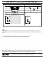
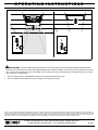
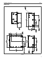
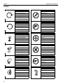
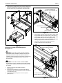
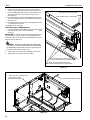
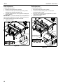
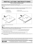
OPERATING INSTRUCTIONS
MODEL: SLEU PROJECTOR LIFT
OPERATION:
WARNING: IMPROPER USE CAN LEAD TO EQUIPMENT FAILURE CAUSING SERIOUS PERSONAL INJURY AND DAMAGE TO
EQUIPMENT! There are NO user servicable parts within the SLEU lift. If lift fails to operate properly immediately contact a Chief Customer
Services Representative by calling 1-800-582-6480
1.
Move control swith to the DOWN position to lower projector lift.
2.
Move control swith to the UP position to raise projector lift.
CSAV, Inc., and its affiliated corporations and subsidiaries (collectively, "CSAV"), intend to make this manual accurate and complete. However, CSAV makes no claim that the information contained herein covers all details, conditions or variations, nor does it provide for every possible contingency in connection with the installation or use of this product. The
information contained in this document is subject to change without notice or obligation of any kind. CSAV makes no representation of warranty, expressed or implied, regarding the
information contained herein. CSAV assumes no responsibility for accuracy, completeness or sufficiency of the information contained in this document.
© 2006 Chief Manufacturing, 8401 Eagle Creek Parkway, Savage, MN 55378
• P: 800.582.6480 / 952.894.6280 • F:877.894.6918 / 952.894.6918
8860-000001
8/17/06
OPERATING INSTRUCTIONS
AVISO: SI NO SE UTILIZA CORRECTAMENTE, EL EQUIPO PODRÍA CAERSE Y CAUSAR GRAVES DAÑOS PERSONALES O
MATERIALES. En el interior del elevador SLEU NO hay ninguna pieza que pueda reparar el usuario. Si el elevador no funciona
correctamente, póngase inmediatamente en contacto con un representante del Departamento de Atención al Cliente de Chief
Manufacturing llamando al número 1-800-582-6480.
1.
Mueva el interruptor de control a la posición DOWN (ABAJO) para bajar el elevador del proyector.
2.
Mueva el interruptor de control a la posición UP (ARRIBA) para subir el elevador del proyector.
CSAV, Inc., and its affiliated corporations and subsidiaries (collectively, "CSAV"), intend to make this manual accurate and complete. However, CSAV makes no claim that the information contained herein covers all details, conditions or variations, nor does it provide for every possible contingency in connection with the installation or use of this product. The
information contained in this document is subject to change without notice or obligation of any kind. CSAV makes no representation of warranty, expressed or implied, regarding the
information contained herein. CSAV assumes no responsibility for accuracy, completeness or sufficiency of the information contained in this document.
© 2006 Chief Manufacturing, 8401 Eagle Creek Parkway, Savage, MN 55378
• P: 800.582.6480 / 952.894.6280 • F:877.894.6918 / 952.894.6918
8860-000001
8/17/06
OPERATING INSTRUCTIONS
WARNUNG: EINE UNSACHGEMÄSSE VERWENDUNG KANN ZUM VERSAGEN DER GERÄTE FÜHREN, WAS SCHWERE
K?RPERVERLETZUNGEN UND SCHÄDEN AN DEN GERÄTEN ZUR FOLGE HAT! Im SLEU-Lift befinden sich keine vom Benutzer zu
wartenden Teile. Wenn der Lift nicht ordnungsgemäß funktioniert, wenden Sie sich umgehend an einen Kundendienstvertreter von Chief
unter der Nummer 1-800-582-6480.
1.
Den Steuerschalter nach UNTEN (DOWN) stellen, um den Projektorlift abzusenken.
2.
Den Steuerschalter nach OBEN (UP) stellen, um den Projektorlift hochzufahren.
CSAV, Inc., and its affiliated corporations and subsidiaries (collectively, "CSAV"), intend to make this manual accurate and complete. However, CSAV makes no claim that the information contained herein covers all details, conditions or variations, nor does it provide for every possible contingency in connection with the installation or use of this product. The
information contained in this document is subject to change without notice or obligation of any kind. CSAV makes no representation of warranty, expressed or implied, regarding the
information contained herein. CSAV assumes no responsibility for accuracy, completeness or sufficiency of the information contained in this document.
© 2006 Chief Manufacturing, 8401 Eagle Creek Parkway, Savage, MN 55378
• P: 800.582.6480 / 952.894.6280 • F:877.894.6918 / 952.894.6918
8860-000001
8/17/06
OPERATING INSTRUCTIONS
ADVERTÊNCIA: O USO INADEQUADO PODE CONDUZIR A FALHA DO EQUIPAMENTO E A CONSEQUENTES LESÕES
PESSOAIS GRAVES E DANOS NO EQUIPAMENTO! NÃO existem peças no interior do elevador SLEU que possam ser reparadas pelo
utilizador. Se o elevador não estiver operacional, contacte imediatamente um representante de assistência ao cliente da Chief através do
telefone 1-800-582-6480.
1.
Desloque o interruptor de controlo para a posição DOWN (BAIXO) para descer o elevador do projector.
2.
Desloque o interruptor de controlo para a posição UP (CIMA) para subir o elevador do projector.
CSAV, Inc., and its affiliated corporations and subsidiaries (collectively, "CSAV"), intend to make this manual accurate and complete. However, CSAV makes no claim that the information contained herein covers all details, conditions or variations, nor does it provide for every possible contingency in connection with the installation or use of this product. The
information contained in this document is subject to change without notice or obligation of any kind. CSAV makes no representation of warranty, expressed or implied, regarding the
information contained herein. CSAV assumes no responsibility for accuracy, completeness or sufficiency of the information contained in this document.
© 2006 Chief Manufacturing, 8401 Eagle Creek Parkway, Savage, MN 55378
• P: 800.582.6480 / 952.894.6280 • F:877.894.6918 / 952.894.6918
8860-000001
8/17/06
OPERATING INSTRUCTIONS
AVVERTENZA: UN USO INADEGUATO PUÒ PROVOCARE UN GUASTO, CON CONSEGUENTI LESIONI GRAVI O DANNI
ALL'APPARECCHIATURA! La piattaforma elevatrice SLEU NON contiene componenti che l'utente può riparare personalmente. Se non
dovesse funzionare correttamente, rivolgersi immediatamente all'assistenza clienti Chief telefonando al numero verde USA 1 800 582
6480.
1.
Portare l'interruttore in posizione DOWN (GIÙ) per abbassare la piattaforma elevatrice del proiettore.
2.
Portare l'interruttore in posizione UP (SU) per alzare la piattaforma elevatrice del proiettore.
CSAV, Inc., and its affiliated corporations and subsidiaries (collectively, "CSAV"), intend to make this manual accurate and complete. However, CSAV makes no claim that the information contained herein covers all details, conditions or variations, nor does it provide for every possible contingency in connection with the installation or use of this product. The
information contained in this document is subject to change without notice or obligation of any kind. CSAV makes no representation of warranty, expressed or implied, regarding the
information contained herein. CSAV assumes no responsibility for accuracy, completeness or sufficiency of the information contained in this document.
© 2006 Chief Manufacturing, 8401 Eagle Creek Parkway, Savage, MN 55378
• P: 800.582.6480 / 952.894.6280 • F:877.894.6918 / 952.894.6918
8860-000001
8/17/06
OPERATING INSTRUCTIONS
WAARSCHUWING: ONJUIST GEBRUIK KAN LEIDEN TOT HET FALEN VAN DE APPARATUUR EN ERNSTIG PERSOONLIJK
LETSEL EN SCHADE AAN DE APPARATUUR VEROORZAKEN! Er zijn GEEN onderdelen in de SLEU Lift waar de gebruiker iets aan kan
doen. Indien de lift niet goed werkt moet u onmiddellijk contact opnemen met een Hoofd Klantendienst Vertegenwoordiger door te bellen
naar het nummer 1-800-562-6480.
1.
Schuif de regelschakelaar naar BENEDEN (DOWN) om de projectorlift omlaag te brengen.
2.
Schuif de regelschakelaar OMHOOG (UP) om de projector lift omhoog te brengen.
CSAV, Inc., and its affiliated corporations and subsidiaries (collectively, "CSAV"), intend to make this manual accurate and complete. However, CSAV makes no claim that the information contained herein covers all details, conditions or variations, nor does it provide for every possible contingency in connection with the installation or use of this product. The
information contained in this document is subject to change without notice or obligation of any kind. CSAV makes no representation of warranty, expressed or implied, regarding the
information contained herein. CSAV assumes no responsibility for accuracy, completeness or sufficiency of the information contained in this document.
© 2006 Chief Manufacturing, 8401 Eagle Creek Parkway, Savage, MN 55378
• P: 800.582.6480 / 952.894.6280 • F:877.894.6918 / 952.894.6918
8860-000001
8/17/06
OPERATING INSTRUCTIONS
WARNING: AVERTISSEMENT : UNE UTILISATION ABUSIVE PEUT CAUSER LA DÉFAILLANCE DE L'ÉQUIPEMENT ET PEUT
CAUSER DES BLESSURES GRAVES ET RÉSULTER EN DES DOMMAGES À L'ÉQUIPEMENT ! Il n'y a aucune pièce pouvant être
échangée par l'utilisateur dans l'élévateur SLEU. Si l'élévateur ne fonctionne pas correctement contactez immédiatement un membre du
service à la clientèle de Chief en appelant le 1-800-582-6480.
1.
Mettre l'interrupteur de contrôle sur la position DOWN (EN BAS) pour abaisser l'élévateur du projecteur.
2.
Mettre l'interrupteur de contrôle sur la position UP (EN HAUT) pour élever l'élévateur du projecteur.
CSAV, Inc., and its affiliated corporations and subsidiaries (collectively, "CSAV"), intend to make this manual accurate and complete. However, CSAV makes no claim that the information contained herein covers all details, conditions or variations, nor does it provide for every possible contingency in connection with the installation or use of this product. The
information contained in this document is subject to change without notice or obligation of any kind. CSAV makes no representation of warranty, expressed or implied, regarding the
information contained herein. CSAV assumes no responsibility for accuracy, completeness or sufficiency of the information contained in this document.
© 2006 Chief Manufacturing, 8401 Eagle Creek Parkway, Savage, MN 55378
• P: 800.582.6480 / 952.894.6280 • F:877.894.6918 / 952.894.6918
8860-000001
8/17/06
INSTALLATION INSTRUCTIONS
Istruzioni di installazione
Installatie-instructies
Instructions d´installation
Instrucciones de instalación
Installationsanleitung
Instruções de Instalação
SMART-LIFT Electric Ceiling Mount
TM
Spanish Product Description
German Product Description
Portuguese Product Description
Italian Product Description
Dutch Product Description
French Product Description
SLEU
SLEU
Installation Instructions
DISCLAIMER
CSAV, Inc., and its affiliated corporations and subsidiaries
(collectively, "CSAV"), intend to make this manual accurate and
complete. However, CSAV makes no claim that the information
contained herein covers all details, conditions or variations, nor
does it provide for every possible contingency in connection
with the installation or use of this product. The information
contained in this document is subject to change without notice
or obligation of any kind. CSAV makes no representation of
warranty, expressed or implied, regarding the information
contained herein. CSAV assumes no responsibility for
accuracy, completeness or sufficiency of the information
contained in this document.
CAUTION: Only use attachments/accessories specified by
manufacturer.
CAUTION: Refer all servicing to qualified personnel.
Servicing is required when the apparatus has been damaged
in any way, such as power supply cord or plug has been
damaged, liquid has been spilled or objects have fallen into
the apparatus, the apparatus has been exposed to rain or
moisture, does not operate normally, or has been dropped.
WARNING: FAILURE TO PROVIDE ADEQUATE
serious injury or death if you do not follow the instructions.
STRUCTURAL SUPPORT FOR THIS LIFT CAN LEAD TO
SEVERE PERSONAL INJURY OR DAMAGE TO
EQUIPMENT! It is the installer’s responsibility to make sure
the structure to which this component is attached can support
five times the combined weight of all equipment. Reinforce
the structure as required before installing the component.
CAUTION: A CAUTION alerts you to the possibility of
WARNING: EXCEEDING THE IDENTIFIED WEIGHT
damage or destruction of equipment if you do not follow the
corresponding instructions.
CAPACITY OF THIS EQUIPMENT CAN LEAD TO SEVERE
PERSONAL INJURY OR DAMAGE TO EQUIPMENT! It is
the installer’s responsibility to make sure the combined
weight of all components attached to the SLEU does not
exceed 35 lbs (16 kg).
IMPORTANT SAFETY INSTRUCTIONS!
WARNING: A WARNING alerts you to the possibility of
CAUTION: Read and keep these instructions and heed all
warnings.
Hazard Label Locations
WARNING: FAILURE TO READ, THOROUGHLY
UNDERSTAND, AND FOLLOW ALL INSTRUCTIONS CAN
LEAD TO SEVER PERSONAL INJURY, DAMAGE TO
EQUIPMENT, OR VOIDING OF FACTORY WARRANTY! It
is the installer’s responsibility to make sure all components
are properly assembled and installed using the instructions
provided.
CAUTION: Clean only with dry cloth.
WARNING: ELECTRIC SHOCK HAZARD! To reduce the
risk of electric shock DO NOT use this apparatus near water,
or expose this apparatus to rain or moisture.
TOOLS REQUIRED FOR INSTALLATION
CAUTION: DO NOT block any ventilation openings and
install only in accordance with these instructions.
CAUTION: DO NOT install near any heat sources such as
radiators, heat registers, stoves, or other apparatus
(including amplifiers) that produce heat.
CAUTION: Protect the power cord from being pinched.
2
#1 / #2
Installation Instructions
SLEU
DIMENSIONS
Figure 1
3
SLEU
Installation Instructions
LEGEND
4
Tighten Fastener
Pencil Mark
Apretar elemento de fijación
Marcar con lápiz
Befestigungsteil festziehen
Stiftmarkierung
Apertar fixador
Marcar com lápis
Serrare il fissaggio
Segno a matita
Bevestiging vastdraaien
Potloodmerkteken
Serrez les fixations
Marquage au crayon
Loosen Fastener
Drill Hole
Aflojar elemento de fijación
Perforar
Befestigungsteil lösen
Bohrloch
Desapertar fixador
Fazer furo
Allentare il fissaggio
Praticare un foro
Bevestiging losdraaien
Gat boren
Desserrez les fixations
Percez un trou
Phillips Screwdriver
Adjust
Destornillador Phillips
Ajustar
Kreuzschlitzschraubendreher
Einstellen
Chave de fendas Phillips
Ajustar
Cacciavite a stella
Regolare
Kruiskopschroevendraaier
Afstellen
Tournevis à pointe cruciforme
Ajuster
Open-Ended Wrench
Remove
Llave de boca
Quitar
Gabelschlüssel
Entfernen
Chave de bocas
Remover
Chiave a punte aperte
Rimuovere
Steeksleutel
Verwijderen
Clé à fourche
Retirez
By Hand
Optional
A mano
Opcional
Von Hand
Optional
Com a mão
Opcional
A mano
Opzionale
Met de hand
Optie
À la main
En option
Target of Projector
Security Wrench
Punto de enfoque del proyector
Llave de seguridad
Ziel des Projektors
Sicherheitsschlüssel
Mira do projector
Chave de segurança
Punto di proiezione
Chiave di sicurezza
Doel van de projector
Veiligheidssleutel
Cible du projecteur
Clé de sécurité
Installation Instructions
SLEU
SITE PREPARATION
Power Requirements and Wiring
Site Preparation
The SLEU requires 220/240VAC 50 Hz power to operate and
draws approximately 80 watts.
Because of the wide variety of possible mounting situations,
Chief Manufacturing can only provide general guidelines for
preparing the location where the SLEU will be installed. Study
the following information carefully, and adapt it as necessary to
fit your specific installation.
WARNING: ELECTRIC SHOCK AND FIRE HAZARD!
IMPROPER INSTALLATION OF WIRING CAN LEAD TO
SEVERE PERSONAL INJURY OR RISK OF FIRE! The
installation of this lift requires it be hard wired. ALWAYS have
wiring installed by a qualified electrician and follow all
electrical codes.
The installation instructions that follow cover the three most
common mounting scenarios:
•
Suspended from a 1 1/2" NPT pipe that is secured to a
structural cross brace in the ceiling.
•
Suspended from three 1/4" threaded rods that are
secured to the structural cross brace.
•
Side-mounted to the ceiling joists, or secured to a wood
framework that is mounted to the ceiling joists.
IMPORTANT ! : If the lift is to be installed in a suspended
ceiling, a CMA-240 Suspended Ceiling Installation Kit is
available as an accessory to fill gap(s) in the ceiling.
2.
Carefully determine the position of the ceiling opening, and
its distance from (throw distance) and orientation to, the
target (area onto which the image will be projected).
Prepare an opening in the ceiling. (See figure 3) also
(See figure 2)
Locate and install lift control switch. (not provided)
WARNING: ELECTRIC SHOCK HAZARD! DO NOT
provide power to switch or energize circuit until lift has been
fully installed in ceiling and all connections have been made
and verified.
2.
Prepare Opening
1.
1.
Connect control wires to switch and route power, lift control,
projector power and signal wires to opening in ceiling.
(See figure 3) and (See figure 4)
IMPORTANT ! : Allow enough excess wiring and cable at the
opening in ceiling to allow wires and cables to be routed into lift
box prior to the lift box being placed into the ceiling.
CAUTION: RUNNING POWER AND SIGNAL CABLE IN
CLOSE PROXIMITY TO ONE ANOTHER CAN LEAD TO
SIGNAL DETERIORATION! ALWAYS route power and
signal wires and cable through separate conduit or a
minimum of 3" apart.
Extra Length for
routing into lift
prior to placing
lift into ceiling.
Figure 2
Lift Control Switch
Figure 3
IMPORTANT ! : It may be necessary to install an outlet inside
the J-Box (within the lift box) in order to provide power to the
projector.
5
SLEU
Installation Instructions
SLEU POWER and CONTROL CIRCUIT
Figure 4
INSTALLATION
6.
Lift pan off lift and set aside.
1/4" threaded Rod Installation
WARNING: IMPROPER INSTALLATION CAN LEAD TO
x4
LIFT FALLING CAUSING SEVERE PERSONAL INJURY OR
DAMAGE TO EQUIPMENT! It is the installers responsibility
to make certain the structure to which the lift is being
mounted is capable of supporting 5 times the weight of the lift
and all attached equipment.
x4
Lift Pan
Flange UP
WARNING: LIFT WEIGHS IN EXCESS OF 65 LBS
(30KG)! ALWAYS use two people and an appropriate lifting
device, and proper lifting techniques when installing or
handling this lift.
The SLEU is designed so that it can be installed by being
suspended from three 1/4-in.-dia. threaded rods (not supplied)
that have been secured to a structural cross brace in the ceiling.
1.
2.
3.
4.
5.
6
Carefully determine the position of the ceiling opening, and
its distance from (throw distance) and orientation to, the
target.
Prepare an opening in the ceiling using the dimensions
shown in figure 2.
Using two people, orient lift so that flanged side is at top and
place it on a flat surface capable of supporting the lift.
Remove four caps on lift pan and set aside for re-use.
Remove four Phillips pan head screws securing pan to lift
and set aside for re-use. (See figure 5)
Figure 5
7.
Install threaded rods to structural cross braces in ceiling.
NOTE: Installing turnbuckles on the threaded rod will make it
easier to level the lift.
Installation Instructions
8.
SLEU
Using two people orient lift so that flanged side is facing
down and motor and electrical junction box are facing away
from target.
Jam Nut
NOTE: Verify lift is in proper orientation with lift front facing
target and flanged side down. (See figure 6)
3/8" Threaded Rods
9. Position and align lift under opening. (See figure 6)
10. Screw three jam nuts on to threaded rods.
NOTE: Jam nuts should be located on rod so that flange of lift
housing is seated against ceiling when cover plate
rests against jam nuts.
11. Carefully raise and position lift so that mounting holes for
threaded rods in lift top cover are aligned with threaded rods
installed in ceiling. (See figure 6)
Figure 7
Installation in a Suspended Ceiling
(using pipe coupler)
The SLEU can be installed by hanging from a 1 1/2" NPT Pipe
and coupling. If this installation is desired contact a Chief
Customer Service Representative and order the optional
mounting kit Model SMA-600.
3/8" Threaded Rod
Flange
Installation in a Wood Framework
The lift housing is designed with joist tabs to allow mounting of
the lift to ceiling joists or other wooden framework.
WARNING: IMPROPER INSTALLATION CAN LEAD TO
LIFT FALLING CAUSING SEVERE PERSONAL INJURY OR
DAMAGE TO EQUIPMENT! It is the installers responsibility
to make certain the structure to which the lift is being
mounted is capable of supporting 5 times the weight of the lift
and all attached equipment.
Figure 6
12. Level lift
WARNING: LIFT WEIGHS IN EXCESS OF 65 LBS
(30KG)! ALWAYS use two people and an appropriate lifting
device, and proper lifting techniques when installing or
handling this lift.
CAUTION: The lift must be installed square and parallel.
Avoid stressing the lift during installation.
1.
Verify lift housing will properly fit within wooden ceiling joists
or construct a framework and secure it to the joists.
(See figure 1)
NOTE: The lift only requires support on two opposing sides.
2.
3.
4.
5.
Using two people, orient lift so that flanged side is at top.
Remove four caps on lift pan. (See figure 8)
Remove four Phillips pan head screws securing pan to lift
and set aside for reuse. (See figure 8)
Remove pan off lift and set aside. (See figure 8)
7
SLEU
Installation Instructions
CAUTION: The lift must be installed square and parallel.
Pan
Avoid stressing the lift during installation.
8.
9.
x4
Verify lift is level and is square in alignment.
Secure the lift to the joists or wood framework using four,
six, or ten 1/4 x1-1/4" lag screws.
IMPORTANT ! : Lag screws must be driven through mounting
x4
tabs in lift housing.
Truss
Lift Housing
Lag or Cap Screw
Flange
Figure 8
6.
7.
Using two people orient lift so that flanged side is facing
down and motor and electrical junction box are facing away
from target.
Using an appropriate lifting device, carefully raise and
position lift so that mounting tabs in lift housing are aligned
with wood trusses, and flange on lift housing is seated
against ceiling.
Flange on Lift Housing
Ceiling Tile
or Drywall
Figure 10
Joists
Mount Projector To Lift
The SLEU is designed to accommodate the installation of
projectors that have been equipped with an appropriate
interface bracket.
IMPORTANT ! : If the projector being mounted does not have
the required interface bracket or the bracket will not work
properly, immediately contact a Chief Customer Service
representative by calling the appropriate number shown on the
back cover of this document.
WARNING: IMPROPER INSTALLATION CAN LEAD TO
Flange
PROJECTOR FALLING CAUSING SEVERE PERSONAL
INJURY OR DAMAGE TO EQUIPMENT! DO NOT substitute
hardware and ALWAYS follow all installation instructions
provided with equipment.
IMPORTANT ! : The combined height of projector and
interface bracket must not exceed 8 1/4" (210mm).
To install projector:
1.
2.
Figure 9
8
Assemble interface bracket to projector following the
instructions provided with the interface bracket.
Orient projector and position under lift cradle, aligning studs
on interface bracket with mounting holes in cradle.
Installation Instructions
3.
SLEU
Raise projector upward until studs on interface bracket are
through mounting holes in cradle, and secure projector to
lift using thumb nuts provided with the interface bracket.
Projector Power Outlet
(Optional, not provided with lift)
Wire extensions (3)
Wire Nuts (3)
J-Box
(Cover removed)
Figure 12
4.
5.
6.
7.
Figure 11
Wiring the Lift and Cable Management
Feed common wire from switch and projector power cable
through Strain relief and into lift housing. (See figure 13)
Feed common wire from switch and projector power cable
through Strain relief and into J-Box. (See figure 13)
Connect projector power to outlet if installed or to projector
following the projector manufacturers instructions.
Connect the common wire from switch to the blue
(common) wire from motor using wire nut.
Projector Power Cable
Common Wire From Switch
Wiring the Lift
WARNING: ELECTRIC SHOCK AND FIRE HAZARD!
IMPROPER INSTALLATION OF WIRING CAN LEAD TO
SEVERE PERSONAL INJURY OR RISK OF FIRE! The
installation of this lift requires it be hard wired. ALWAYS have
wiring installed by a qualified electrician and follow all
electrical codes.
WARNING: ELECTRIC SHOCK HAZARD! DO NOT
provide power to switch or energize circuit until lift has been
fully installed in ceiling and all connections have been made
and verified.
1.
2.
3.
Remove cover from J-Box inside lift housing.
(See figure 12)
Disconnect wire extensions from wires inside J-Box by
turning wire nuts counterclockwise. Set wire nuts aside for
re-use. (See figure 12)
Install outlet for projector power in J-box if required.
(See figure 12)
Blue wire from Motor
Common Wire From Switch
Figure 13
9
SLEU
Installation Instructions
8.
Feed control wires from UP and Down sides of control
switch through strain relief and into J-Box. (See figure 14)
9. Connect the BROWN wire from the UP limit switch to the
wire from the UP side of control switch using a wire nut.
(See figure 14)
10. Connect the BLACK wire from the DOWN limit with to the
wire from the DOWN side of control switch using a wire nut.
(See figure 14)
11. Carefully place all connections into J-Box making sure wire
nut connections stay in tact.
12. Replace cover onto J-Box.
From UP side of Control Switch
From DOWN side of Control Switch
Cable Routing and Management
1.
Feed video/communication cable through strain relief on the
rear of lift housing, and connect to projector.
(See
figure 15)
IMPORTANT ! : The lift carriage travels approximately 8 1/2"
(215mm) when moving from fully UP to fully DOWN position.
Wires and cables connected the projector MUST be of proper
length to allow for this travel.
WARNING: IMPROPER WIRE AND CABLE ROUTING
CAN LEAD TO LOSS OF SIGNAL QUALITY OR DAMAGE
TO EQUIPMENT. Make certain wires are routed away from
pinch points and properly secured to lift.
2.
3.
Secure video or communications cable(s) to lift housing.
Tighten strain relief screws to secure cables.
Brown wire from UP Limit switch
to wire from UP side of Control Switch
Black wire from DOWN Limit switch
to wire from Down side of Control Switch
Figure 14
Allow for 81/2" of carriage travel
when routing cables.
(Carriage shown down)
Video/Communications Cables
Figure 15
10
Installation Instructions
4.
5.
SLEU
Install lift pan to lift carriage using four Phillips pan head
screws.
Install four screw covers onto lift pan.
Yaw Adjustment
To adjust projector YAW:
1.
2.
3.
4.
Move the lift to the fully “down” position.
Loosen four screws (two on each end of cradle assembly)
securing projector mounting bracket to cradle.
(See figure 17)
Move one end of projector mounting bracket towards front
or rear of lift until image is properly aligned. (See figure 17)
Tighten four screws.
Cradle
Projector Mounting
Bracket
X4
x4
Lift Carriage
Lift Pan
x4
Figure 16
6.
Connect lift power supply cable to control switch to energize
the lift circuit.
WARNING: LIFT MAY MOVE WITOUT WARNING WHEN
INITIALLY POWERED ALEADING TO SEVER PERSONAL
INJURY. ALWAYS keep fingers, hands and clothing away
from lift pan when lift is operating.
Figure 17
ADJUSTMENTS
The SLEU is designed to provide projector throw adjustments in
the YAW, Pitch and Roll directions.
WARNING: ADJUSTMENTS REQUIRE LIFT AND
PROJECTOR TO POWER SUPPLY TO BE "ON". Keep
hands and clothing away from moving parts.
Continued
11
SLEU
Installation Instructions
Pitch Adjustment
Roll Adjustment
To adjust projector PITCH:
To adjust projector ROLL:
1.
2.
1.
2.
3.
Move the lift to the fully “down” position.
Loosen four screws (two on each end) securing cradle
assembly to lift carriage. (See figure 18)
Tip cradle towards front or rear of projector until image is
properly aligned.
IMPORTANT ! : The cradle assembly can be repositioned to
3.
4.
Move the lift to the fully “down” position.
Loosen four screws securing each end of projector
mounting bracket to cradle.
Move one end of projector mounting bracket up or down
until image is properly aligned.
Tighten four screws.
assist in projector alignment, however, cradle mounting must
mirror holes and slots from one side to the other.
4.
Tighten four screws.
Cradle
Lift Carriage
Projector Mounting
Bracket
Cradle
X4
X2
Figure 18
Figure 19
12
Installation Instructions
SLEU
13
SLEU
Installation Instructions
USA/International
Europe
Asia Pacific
8820-000004 Rev B
2006 Chief Manufacturing
www.chiefmfg.com
05/06
A
P
F
A
P
F
A
8401 Eagle Creek Parkway, Savage, MN 55378
800.582.6480 / 952.894.6280
877.894.6918 / 952.894.6918
Fellenoord 130 5611 ZB EINDHOVEN, The Netherlands
+31 (0)40 2668620
+31 (0)40 2668615
Room 30I, Block D, Lily YinDu International Building
LuoGang, BuJi Town, Shenzhen, CHINA. Post Code: 518112
P +86-755-8996 9226 ; 8996 9236 ; 8996 9220
F +86-755-8996 9217