1
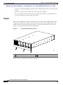
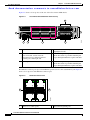
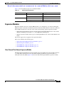
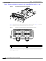
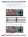
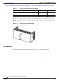
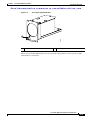
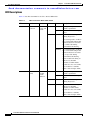
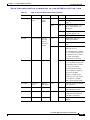
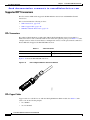
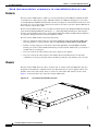
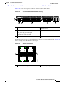
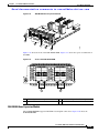
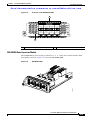
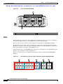
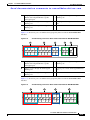
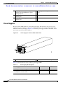
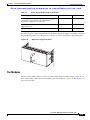
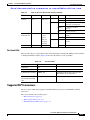
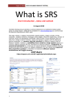
Send documentation comments to [email protected]
CH A P T E R
2
Cisco Nexus 5000 Series Overview
This chapter describes the Cisco Nexus 5000 series switches. This chapter includes the following
sections:
•
Cisco Nexus 5020 Switch, page 2-1
•
Cisco Nexus 5010 Switch, page 2-17
Cisco Nexus 5020 Switch
This section describes the Cisco Nexus 5020 switches. This section includes the following sections:
•
Features, page 2-1
•
Chassis, page 2-2
•
Ports, page 2-9
•
Expansion Modules, page 2-5
•
Power Supply, page 2-11
•
Fan Modules, page 2-12
•
LED Descriptions, page 2-14
•
Supported SFP Transceivers, page 2-16
Features
The Cisco Nexus 5020 switch is a 2 RU, top-of-rack switch that provides Ethernet and Fibre Channel
consolidation in a single physical cable. The Fibre Channel over Ethernet (FCoE) protocol is used to
consolidate Ethernet and Fibre Channel traffic onto the same physical connection between the server and
the switch. As a top-of-rack switch, all the servers in the rack connect to the Cisco Nexus 5020 switch,
and it connects to the LAN or SAN.
The Cisco Nexus 5020 switch is a part of a family of switches that provide 10-Gigabit Ethernet and FCoE
ports and both 10-Gigabit Ethernet and native 1-, 2-, and 4-Gbps Fibre Channel ports. The switches
provide consolidated I/O connectivity to both production Ethernet LANs and Fibre Channel SANs in a
cost-effective, high-performance, low-latency Ethernet switch.
The Cisco Nexus 5020 switch has the following features:
•
Forty fixed 10-Gigabit Ethernet server connection ports on the back of the switch
Cisco Nexus 5000 Series Hardware Installation Guide
OL-15902-01
2-1
Chapter 2
Cisco Nexus 5000 Series Overview
Cisco Nexus 5020 Switch
Send documentation comments to [email protected]
•
Two slots for optional 10-Gigabit expansion modules or Fibre Channel interfaces on the back of the
switch
•
Two slots on the front of the switch for hot swap-capable power supplies
•
Five slots on the front of the switch for hot swap-capable fan modules, each of which houses two
fans, that provide front-to-back cooling for the switch
Chassis
The Cisco Nexus 5020 chassis is 2 RU (3.47 inches) tall, 17.3 inches wide, and 30.0 inches deep. It is
designed to be mounted in a standard 19-inch rack. The switch has two power supplies and five fans
modules on the front of the switch. Ports are at the rear of the switch. The airflow is front to back.
Figure 2-1 shows the front of the Cisco Nexus 5020 switch.
Figure 2-1
Cisco Nexus 5020 Switch Front View
186260
1
2
3
1
Two power supplies
2
Five fan modules
Figure 2-2 shows a close-up view of the front of the switch.
Cisco Nexus 5000 Series Hardware Installation Guide
2-2
OL-15902-01
Chapter 2
Cisco Nexus 5000 Series Overview
Cisco Nexus 5020 Switch
Send documentation comments to [email protected]
Figure 2-2
Cisco Nexus 5020 Switch Front View Close-up
2
3
186261
1
1
Two power supplies
2
Five fan modules
3
System status LED
The rear of the Cisco Nexus 5020 chassis has 40 fixed 10-Gigabit Ethernet ports, 2 slots for optional
expansion modules, an Ethernet connector with 2 cross-connect ports and 2 management ports, a console
port, and 2 AC power connectors. Figure 2-3 shows the rear of the Cisco Nexus 5020 switch.
Figure 2-3
Cisco Nexus 5020 Switch Rear View
1
2
4
5
186265
3
6
1
System status LED
4
40 fixed 10-Gigabit Ethernet ports
2
Ethernet connector with two cross-connect
ports on the left (top and bottom), and two
network management ports on the right (top
and bottom)
5
Expansion modules, shown here with two
4-port Fibre Channel plus 4-port 10-Gigabit
Ethernet expansion modules
3
Console port
6
AC power connectors
Cisco Nexus 5000 Series Hardware Installation Guide
OL-15902-01
2-3
Chapter 2
Cisco Nexus 5000 Series Overview
Cisco Nexus 5020 Switch
Send documentation comments to [email protected]
Figure 2-4 shows a close-up view of the rear of the Cisco Nexus 5020 chassis.
Figure 2-4
Cisco Nexus 5020 Switch Rear View Close-up
5
2
3
4
6
186263
7
1
1
System status LED
4
Slot 1, with 40 fixed 10-Gigabit Ethernet ports
(highlighted in red).
2
Ethernet connector with two cross-connect
ports on left side, and two network
management1 (top) and management2
(bottom) ports on the right side
5
Slot 2 for an optional expansion module;
shown here with a 4-port Fibre Channel plus
4-port 10-Gigabit Ethernet expansion module
3
Console port
6
Slot 3 for an optional expansion module;
shown here with a 4-port Fibre Channel plus
4-port 10-Gigabit Ethernet expansion module
The Ethernet connector port exposes four Ethernet ports that are in a 2x2 stacked RJ-45 jack. Figure 2-5
shows a close-up view of the Ethernet connector port.
Figure 2-5
Ethernet Connector Port
2
186385
1
1
Internal cross connect ports
2
Network management ports
Cisco Nexus 5000 Series Hardware Installation Guide
2-4
OL-15902-01
Chapter 2
Cisco Nexus 5000 Series Overview
Cisco Nexus 5020 Switch
Send documentation comments to [email protected]
Table 2-1 lists the LED descriptions for all Ethernet LEDs.
Table 2-1
Ethernet LED Descriptions
LED
Status
Description
Left
Off
No link
Solid green
Physical link
Off
No activity
Blinking green
Activity
Right
Expansion Modules
Expansion modules allow Cisco Nexus 5000 switches to be configured as cost-effective 10-Gigabit
Ethernet switches and as I/O consolidation platforms with native Fibre Channel connectivity. The Cisco
Nexus 5020 switch has two slots that can be used for the following optional expansion modules:
•
Fibre Channel plus Ethernet expansion module with four 10-Gigabit Ethernet Cisco Data Center
Ethernet and FCoE ports and four 1-, 2-, and 4-Gbps Fibre Channel ports
•
Ethernet expansion module with six ports of 10-Gigabit Ethernet Cisco Data Center Ethernet and
FCoE
The chassis supports hot swapping of the expansion modules
This section includes the following topics:
•
Fibre Channel Plus Ethernet Expansion Module, page 2-5
•
Ethernet Expansion Module, page 2-7
•
N5K-M1008 Gatos Expansion Module, page 2-7
•
N5K-M1060 Gatos Expansion Module, page 2-8
Fibre Channel Plus Ethernet Expansion Module
The Fibre Channel plus Ethernet expansion module supports four SFP+ transceiver modules and four 1-,
2-, 4-Gbps Fibre Channel transceivers. The Fibre Channel plus Ethernet expansion module is a
field-replaceable unit (FRU). Figure 2-6 shows the Fibre Channel plus Ethernet expansion module.
Cisco Nexus 5000 Series Hardware Installation Guide
OL-15902-01
2-5
Chapter 2
Cisco Nexus 5000 Series Overview
Cisco Nexus 5020 Switch
Send documentation comments to [email protected]
Figure 2-6
Fibre Channel Plus Ethernet Expansion Module
1
2
3
186384
4
5
Figure 2-7 shows the front of the Fibre Channel plus Ethernet expansion module. Figure 2-13 shows how
ports are numbered on the Fibre Channel plus Ethernet expansion module.
Front View of the Fibre Channel Plus Ethernet Expansion Module f
10 GIGABIT ETHERNET
1
2
3
1/2/4G FIBRE CHANNEL
4
1
2
1
1
Four 10-Gigabit Ethernet ports
2
Module LED
3
4
186258
Figure 2-7
2
3
Four 1-, 2-, 4-Gbps Fibre Channel ports
See Figure 2-13 for an illustration of how ports are grouped and numbered on the Fibre Channel plus
Ethernet expansion module.
Cisco Nexus 5000 Series Hardware Installation Guide
2-6
OL-15902-01
Chapter 2
Cisco Nexus 5000 Series Overview
Cisco Nexus 5020 Switch
Send documentation comments to [email protected]
Ethernet Expansion Module
The Ethernet expansion module supports six 10-Gigabit Ethernet ports, four of which will have
encryption capability. The Ethernet expansion module is a field-replaceable unit (FRU). Figure 2-8
shows the Ethernet expansion module.
Figure 2-8
Ethernet Expansion Module
3
3
1
1
2
3
4
5
6
186259
10 GIGABIT ETHERNET
2
4
1
10-Gigabit Ethernet ports
2
Module LED
3
10-Gigabit Ethernet ports
See Figure 2-14 for an illustration of how ports are grouped and numbered on the Ethernet expansion
module.
N5K-M1008 Gatos Expansion Module
The N5K-M1008 GEM supports 8 1/2/4G Fiber Channel, SFP-based uplink connection. Figure 2-9
shows the N5K-M1008 GEM.
Cisco Nexus 5000 Series Hardware Installation Guide
OL-15902-01
2-7
Chapter 2
Cisco Nexus 5000 Series Overview
Cisco Nexus 5020 Switch
Send documentation comments to [email protected]
N5K-M1008 GEM
Figure 2-10
Front View of the N5K-M1008 GEM
189953
Figure 2-9
1
2
3
4
5
6
7
8
189954
1
2
1
Eight 1-, 2-, 4-Gbps Fibre Channel ports
2
LED
N5K-M1060 Gatos Expansion Module
The N5K-M1060 xpansion module provides 6 EA 1/2/4/8G line rate Fiber Channel, SFP+ based uplink
connections. Figure 2-11 and Figure 2-12 show the N5K-M1060 GEM.
Cisco Nexus 5000 Series Hardware Installation Guide
2-8
OL-15902-01
Chapter 2
Cisco Nexus 5000 Series Overview
Cisco Nexus 5020 Switch
Send documentation comments to [email protected]
N5K-M1060 GEM
Figure 2-12
Front View of the N5K-M1060 GEM
196118
Figure 2-11
1
1
2
3
4
5
6
196117
1/2/4/8G FIBRE CHANNEL
2
1
Six 1-, 2-, 4-, 8-Gbps Fibre Channel ports
2
LED
Ports
Each individual port on the Cisco Nexus 5020 switch is numbered, and groups of ports are numbered
based on their function. The ports are numbered top to bottom and left to right. The 40 fixed ports form
group 1 and are named 1/port_number. Ports 1 through 32 are unencrypted Ethernet ports. Of these, ports
1 through 16 are 10-Gigabit Ethernet and 1-Gigabit Ethernet capable ports. Ports 33 through 40 are
encryption-capable Ethernet ports.
Group 2 includes the ports in the top-most expansion module. Group 2, ports 1 through 4, are encrypted
Ethernet ports. Group 2, ports 5 through 8, are Fibre Channel ports.
Cisco Nexus 5000 Series Hardware Installation Guide
OL-15902-01
2-9
Chapter 2
Cisco Nexus 5000 Series Overview
Cisco Nexus 5020 Switch
Send documentation comments to [email protected]
Group 3 includes the ports in the bottom-most expansion module. Group 3 ports 1 through 4 are
encrypted Ethernet ports. Group 3 ports 5 through 8 are Fibre Channel ports.
Figure 2-13 shows how ports are numbered and grouped by function for both the fixed ports and the
Fibre Channel plus Ethernet expansion module ports.
Figure 2-13
Port Numbering of Fixed Ports and Fibre Channel Plus Ethernet Expansion Module
Ports
B
C
D
E
186386
A
A
Group 1, ports 1 through 16: 10-Gigabit
Ethernet and 1-Gigabit Ethernet capable
unencrypted ports
D
Groups 2 and 3, ports 1 through 4: Encrypted
Ethernet ports
B
Group 1, ports 1 through 32: Unencrypted
Ethernet ports
E
Groups 2 and 3, ports 5 through 8: Fibre
Channel ports
C
Group 1, ports 33 through 40: Encrypted
Ethernet ports
Figure 2-14 shows how ports are numbered and grouped by function for both the fixed ports and the
Ethernet expansion module ports.
Figure 2-14
Port Numbering of Fixed Ports and the Ethernet Expansion Module
B
C
D
E
186387
A
Cisco Nexus 5000 Series Hardware Installation Guide
2-10
OL-15902-01
Chapter 2
Cisco Nexus 5000 Series Overview
Cisco Nexus 5020 Switch
Send documentation comments to [email protected]
A
Group 1, ports 1 through 16: 10-Gigabit
Ethernet and 1-Gigabit Ethernet capable
Encrypted ports
D
Groups 2 and 3, ports 1 through 4: Encrypted
Ethernet ports
B
Group 1, ports 1 through 32: Unencrypted
Ethernet ports
E
Groups 2 and 3, ports 5 through 6:
Unencrypted Ethernet ports
C
Group 1, ports 33 through 40: Encrypted
Ethernet ports
Power Supply
The Cisco Nexus 5020 switch uses a front-end power supply. The chassis has slots for two power
supplies. Two power supplies can be used for redundancy, but the Cisco Nexus 5020 switch is fully
functional with one power supply. Figure 2-15 shows the power supply, which has two LEDs: one for
the power status and one for the failure condition.
Power Supply for the Cisco Nexus 5020 Switch
1
1
186264
Figure 2-15
2
Green power LED indicates the power status. 2
Amber fail LED indicates a failure condition.
Table 2-2 table describes the status of the two power supply LEDs.
Table 2-2
Power Supply LED Descriptions
Power Supply Condition
Power LED Status
Fail LED Status
No AC power to all power supplies.
Off
Off
Power supply failure, including overvoltage, overcurrent, Off
overtemperature, and fan failure.
On
Power supply warning events where the power supply
continues to operate. These events include high
temperature, high power, and slow fan.
Blinking
Off
Cisco Nexus 5000 Series Hardware Installation Guide
OL-15902-01
2-11
Chapter 2
Cisco Nexus 5000 Series Overview
Cisco Nexus 5020 Switch
Send documentation comments to [email protected]
Table 2-2
Power Supply LED Descriptions (continued)
Power Supply Condition
Power LED Status
Fail LED Status
AC present, 3.3 voltage standby (VSB) on, and the power 1 Hz blinking
supply unit is off.
Off
Power supply on and OK.
Off
On
If you have one power supply installed in the chassis, but the other power supply slot is empty, you
should use a blank filler panel to cover the empty slot. Figure 2-16 shows a blank power supply filler
panel.
Blank Power Supply Filler Panele
186854
Figure 2-16
Fan Modules
The Cisco Nexus 5020 switch has five fan modules. Figure 2-17 shows the fan module.
Cisco Nexus 5000 Series Hardware Installation Guide
2-12
OL-15902-01
Chapter 2
Cisco Nexus 5000 Series Overview
Cisco Nexus 5020 Switch
Send documentation comments to [email protected]
Figure 2-17
Cisco Nexus 5020 Fan Module
186263
1
1
Fan module LED
The bicolor fan module LED indicates the fan tray health. Green indicates normal operation, while
amber indicates a fan failure.
Cisco Nexus 5000 Series Hardware Installation Guide
OL-15902-01
2-13
Chapter 2
Cisco Nexus 5000 Series Overview
Cisco Nexus 5020 Switch
Send documentation comments to [email protected]
LED Descriptions
Table 2-3 describes the LEDs for the Cisco Nexus 5020 switch.
Table 2-3
LEDs for the Cisco Nexus 5020 Switch
LED
Location
Chassis
Front and back Chassis
of chassis
power and
health
Function
Color
Status
Description
Green
Solid on
All diagnostics pass. The
module is operational.
Off
The module is not receiving
power.
On
The module is booting or
running diagnostics.
Amber
An overtemperature condition
has occurred. The temperature
threshold has been exceeded
by a small value during
environmental monitoring.
Blinking
An overtemperature condition
has occurred. The temperature
threshold has been exceeded
by a large value during
environmental monitoring.
If the module fails during an
initial reset, the LED
continues to blink and the
module does not come online.
The module has a runtime
failure and is brought offline.
Fan module
Fan modules
(front)
Fan
module
health
indicator
Solid on
All diagnostics pass. The
module is operational.
Off
The module is not receiving
power.
Amber
Solid on
The module is booting or
running diagnostics.
Amber
Blinking
If the module fails during an
initial reset, the LED
continues to blink and the
module does not come online.
Green
The module has a runtime
failure and is brought offline.
Cisco Nexus 5000 Series Hardware Installation Guide
2-14
OL-15902-01
Chapter 2
Cisco Nexus 5000 Series Overview
Cisco Nexus 5020 Switch
Send documentation comments to [email protected]
Table 2-3
LEDs for the Cisco Nexus 5020 Switch (continued)
LED
Location
Power supply Power supply
(front)
Function
Color
Status
Description
Power
supply
health
Green
Solid on
Power supply is on and okay.
Off
No AC power to the power
supply.
Solid on
Power supply failures, over
voltage, over current, over
temperature.
Amber
Blinking AC is present, 3.3 VSB on, and
the power supply is off.
Module
Back of chassis Indicator
of a fault
with any
expansion
module
Green
Amber
Off
Operating normally.
On
All diagnostics pass. The
module is operational.
Off
The module is not receiving
power.
Solid on
The module is booting or
running diagnostics.
An overtemperature condition
has occurred. The temperature
threshold has been exceeded
by a small value during
environmental monitoring.
Blinking
An overtemperature condition
has occurred. The temperature
threshold has been exceeded
by a large value during
environmental monitoring.
If the module fails during an
initial reset, the LED
continues to blink and the
module does not come online.
The module has a runtime
failure and is brought offline
Port LED
Back of the
chassis
Indicates
Green
LED status
Amber
Off
The port is not active or the link
is not connected.
Solid on
The port is active. The link is
connected and operational.
Solid on
The module or port is disabled
through the CLI command or
the module is initializing.
Blinking
The port is faulty and has been
disabled.
Cisco Nexus 5000 Series Hardware Installation Guide
OL-15902-01
2-15
Chapter 2
Cisco Nexus 5000 Series Overview
Cisco Nexus 5020 Switch
Send documentation comments to [email protected]
Supported SFP Transceivers
The Cisco Nexus 5020 switch supports both SFP+ Ethernet transceivers and SFP Fibre Channel
transceivers.
This section includes the following sections:
•
SFP+ Transceivers, page 2-16
•
SFP+ Copper Cables, page 2-16
•
SFP Fiber Channel Transceivers, page 2-17
SFP+ Transceivers
The enhanced Small-Form-Factor Pluggable (SFP+) 10-Gigabit Ethernet transceiver module is a
bidirectional device with a transmitter and receiver in the same physical package. SeeTable 2-4 . It has
a 20-pin connector on the electrical interface and duplex LC connector on the optical interface.The Cisco
Nexus 5020 switch supports the SFP-10G-SR transceiver.
Table 2-4
SFP+ Transceivers
Model
Description
SFP-10G-SR
10-Gigabit Ethernet—short range SFP+ module
Figure 2-18 shows the SFP-10G-SR transceiver.
SFP+ 10-Gigabit Ethernet Transceiver Module
187492
Figure 2-18
SFP+ Copper Cables
Copper cables are available for use with the 10-Gigabit Ethernet SFP+ module. See Table 2-5. The
cables come in the following lengths:
•
1m, 30AWG
•
3m, 28-30 AWG
Cisco Nexus 5000 Series Hardware Installation Guide
2-16
OL-15902-01
Chapter 2
Cisco Nexus 5000 Series Overview
Cisco Nexus 5010 Switch
Send documentation comments to [email protected]
•
5m, 26-28 AWG
Table 2-5
SFP+ Copper Cables
Model
Description
SFP-H10GB-CU1M
10GBASE-CU SFP+ Cable 1 Meter
SFP-H10GB-CU3M
10GBASE-CU SFP+ Cable 3 Meter
SFP-H10GB-CU5M
10GBASE-CU SFP+ Cable 5 Meter
SFP Fiber Channel Transceivers
The Cisco Nexus 5020 switch also supports the following SFP Fibre Channel transceivers (See
Table 2-6) :
Table 2-6
SFP Fiber Channel Transceivers
Model
Description
DS-SFP-FC4G-SW
4-Gbps/2-Gbps/1-Gbps Fibre Channel—short
wavelength SFP module
Cisco Nexus 5010 Switch
This section describes the Cisco Nexus 5010 switch and its components. This section includes the
following topics:
•
Features, page 2-18
•
Chassis, page 2-18
•
Expansion Modules, page 2-22
•
Ports, page 2-26
•
Power Supplies, page 2-28
•
Fan Modules, page 2-29
•
LED Descriptions, page 2-30
•
Supported SFP Transceivers, page 2-31
Cisco Nexus 5000 Series Hardware Installation Guide
OL-15902-01
2-17
Chapter 2
Cisco Nexus 5000 Series Overview
Cisco Nexus 5010 Switch
Send documentation comments to [email protected]
Features
The Cisco Nexus 5010 switch is a 1RU, top-of-rack switch that provides Ethernet and Fibre Channel
consolidation in a single physical cable. The Fibre Channel over Ethernet (FCoE) protocol is used to
consolidate Ethernet and Fibre Channel traffic onto the same physical connection between the server and
the switch. As a top-of-rack switch, all the servers in the rack connect to the Cisco Nexus 5010 switch,
and it connects to the LAN or SAN.
The Cisco Nexus 5010 switch is a part of a family of switches that provide 10-Gigabit Ethernet and FCoE
ports and both 10-Gigabit Ethernet and native 1-, 2-, and 4-Gbps Fibre Channel ports. The switches
provide consolidated I/O connectivity to both production Ethernet LANs and Fibre Channel SANs in a
cost-effective, high-performance, low-latency Ethernet switch.
The Cisco Nexus 5010 switch has the following features:
•
One slot on the back of the switch for an optional uplink Gatos Expansion Module [GEM]. The
following modules can be inserted into this slot: N5K-M1404, N5K-M1600 and N5K-M1008.
•
Twenty to twenty-eight ports on the back of the switch depending on which GEM is installed.
Twenty ports on Cisco Nexus 5010 switch belong to the base switch. Additionally, you an insert a a
module with six or eight ports.
•
Two slots on the front of the switch for hot swap-capable power supplies.
•
Two slots on the front of the switch for fan modules. Each fan module houses six fans. The
combination of six fans per module and two modules provides the switch with a total of 12-fans.
Chassis
The Cisco Nexus 5010 chassis is 1 RU, 1.72 inches tall, 17.3 inches wide and 30.0 inches deep. It is
designed to be mounted in a standard 19-inch rack. The switch has two power supplies and two fans
modules on the front of the switch. Ports are at the rear of the switch. The airflow is front to back.
Figure 2-19 shows the front view of the Cisco Nexus 5010 switch.
Cisco Nexus 5010 Switch Front View
189949
Figure 2-19
1
2
Cisco Nexus 5000 Series Hardware Installation Guide
2-18
OL-15902-01
Chapter 2
Cisco Nexus 5000 Series Overview
Cisco Nexus 5010 Switch
Send documentation comments to [email protected]
1
2
Two power supplies
Two fan modules
Figure 2-20 shows a close-up view of the front of the switch.
Figure 2-20
Cisco Nexus 5010 Switch Front View Close-up
1
3
189950
2
1
Two power supplies
2
Two fan modules
3
System status LED
The rear of the Cisco Nexus 5010 chassis has 20 fixed 10-Gigabit Ethernet ports, 1 slot for an optional
expansion module, an Ethernet connector with 2 cross-connect ports and 2 management ports, a console
port, and 2 AC power connectors. Figure 2-21 shows the rear of the Cisco Nexus 5010 switch.
Figure 2-21
Cisco Nexus 5010 Switch Rear View
1
3
189951
2
4
5
6
Cisco Nexus 5000 Series Hardware Installation Guide
OL-15902-01
2-19
Chapter 2
Cisco Nexus 5000 Series Overview
Cisco Nexus 5010 Switch
Send documentation comments to [email protected]
1
System status LED
4
20 fixed 10-Gigabit Ethernet ports
2
Ethernet connector with two cross-connect
ports on the left (top and bottom), and two
network management ports on the right (top
and bottom)
5
Expansion modules
3
Console port
6
AC power connectors
Cisco Nexus 5000 Series Hardware Installation Guide
2-20
OL-15902-01
Chapter 2
Cisco Nexus 5000 Series Overview
Cisco Nexus 5010 Switch
Send documentation comments to [email protected]
Figure 2-22 shows a close-up view of the rear of the Cisco Nexus 5010 chassis.
Figure 2-22
Cisco Nexus 5010 Switch Rear View Close-up
189952
1
2
3
5
4
6
1
System status LED
4
Slot 1, with 20 fixed 10-Gigabit Ethernet ports
(highlighted in red).
2
Ethernet connector with two cross-connect
ports on left side and two network
management1 (top) and management2
(bottom) ports on the right side
5
Slot 2 for an optional expansion module
3
Console port
6
AC power connectors
The Ethernet connector port exposes four Ethernet ports that are in a 2x2 stacked RJ-45 jack. Figure 2-23
shows a close-up view of the Ethernet connector port.
Figure 2-23
Ethernet Connector Port
2
186385
1
1
Internal cross connect ports
2
Network management ports
Cisco Nexus 5000 Series Hardware Installation Guide
OL-15902-01
2-21
Chapter 2
Cisco Nexus 5000 Series Overview
Cisco Nexus 5010 Switch
Send documentation comments to [email protected]
Table 2-7 lists the LED descriptions for all Ethernet LEDs.
Table 2-7
Ethernet LED Descriptions
LED
Status
Description
Left
Off
No link
Solid green
Physical link
Off
No activity
Blinking green
Activity
Right
Expansion Modules
Expansion modules allow Cisco Nexus 5000 switches to be configured as cost-effective 10-Gigabit
Ethernet switches and as I/O consolidation platforms with native Fibre Channel connectivity. The Cisco
Nexus 5010 switch has one slot for an optional uplink Gatos Expansion Module (GEM). The following
modules can be inserted in this slot: N5K-M1404, N5K-M1600, N5K-M1008 and N5K-M1060.
•
N5K-M1404 provides 4 10G SFP+, and 4 Fiber Channel 1/2/4G SFP based uplink connections. The
10-Gigabit Ethernet ports are encryption capable.
•
M5K-M1600 provides 6 10G SFP+ based uplink connections.
•
N5K-M1008 provides 8 1-, 2-, and 4- Gps Fiber Channel, SFP based uplink connection.
•
N5K-M1060 provides 6 1-, 2-, 4-, and 8-Gbps line rate Fiber Channel, SFP+ based uplink
connections.
The chassis supports hot swapping of the expansion modules.
This section includes the fllowing topics:
•
N5K-M1404 Gatos Expansion Module, page 2-22
•
N5K-M1600 Gatos Expansion Module, page 2-23
•
N5K-M1008 Gatos Expansion Module, page 2-24
•
N5K-M1060 Gatos Expansion Module, page 2-25
N5K-M1404 Gatos Expansion Module
The N5K-M1404 GEM supports four SFP+ transceiver modules and four 1-, 2-, 4-Gbps Fibre Channel
transceivers. The N5K-M1404 Fibre Channel plus Ethernet expansion module is a field-replaceable unit
(FRU). Figure 2-24 shows the Fibre Channel plus Ethernet expansion module.
Cisco Nexus 5000 Series Hardware Installation Guide
2-22
OL-15902-01
Chapter 2
Cisco Nexus 5000 Series Overview
Cisco Nexus 5010 Switch
Send documentation comments to [email protected]
Figure 2-24
N5K-M1404 Gatos Expansion Module
1
2
3
186384
4
5
Figure 2-25 shows the front of the N5K-M1404 GEM . Figure 2-13 shows how ports are numbered on
the GEM.
Front of the N5K-M1404 GEM
10 GIGABIT ETHERNET
1
2
3
1/2/4G FIBRE CHANNEL
4
1
2
1
1
Four 10-Gigabit Ethernet ports
2
Module LED
3
4
186258
Figure 2-25
2
3
Four 1-, 2-, 4-Gbps Fibre Channel ports
N5K-M1600 Gatos Expansion Module
The N5K-M1600 GEM supports 6 10G SFP+ based uplink connections. Figure 2-26 shows the
N5K-M1600 GEM.
Cisco Nexus 5000 Series Hardware Installation Guide
OL-15902-01
2-23
Chapter 2
Cisco Nexus 5000 Series Overview
Cisco Nexus 5010 Switch
Send documentation comments to [email protected]
Figure 2-26
N5K-M1600 GEM
3
3
1
1
2
3
4
5
6
186259
10 GIGABIT ETHERNET
2
4
1
10-Gigabit Ethernet ports
2
Module LED
3
10-Gigabit Ethernet ports
See Figure 2-14 for an illustration of how ports are grouped and numbered on the Ethernet expansion
module.
N5K-M1008 Gatos Expansion Module
The N5K-M1008 GEM supports 8 1/2/4G Fiber Channel, SFP-based uplink connection. Figure 2-27 and
Figure 2-28 show the N5K-M1008 GEM.
N5K-M1008 GEM
189953
Figure 2-27
Cisco Nexus 5000 Series Hardware Installation Guide
2-24
OL-15902-01
Chapter 2
Cisco Nexus 5000 Series Overview
Cisco Nexus 5010 Switch
Send documentation comments to [email protected]
Figure 2-28
Front View of the N5K-M1008 GEM
1
2
3
4
5
6
7
8
189954
1
2
1
Eight 1-, 2-, 4-Gbps Fibre Channel ports
2
LED
N5K-M1060 Gatos Expansion Module
The N5K-M1060 expansion module provides 6 EA 1-, 2-, 4-, 8-Gbps line rate Fiber Channel, SFP+
based uplink connections. Figure 2-27 shows the N5K-M1060 GEM.
N5K-M1060 GEM
196118
Figure 2-29
Cisco Nexus 5000 Series Hardware Installation Guide
OL-15902-01
2-25
Chapter 2
Cisco Nexus 5000 Series Overview
Cisco Nexus 5010 Switch
Send documentation comments to [email protected]
Figure 2-30
Front of the N5K-M1060 GEM
1
1
4
3
2
196117
1/2/4/8G FIBRE CHANNEL
6
5
2
1
Six 1-, 2-, 4-, 8-Gbps Fibre Channel ports
2
LED
Ports
Each individual port on the Cisco Nexus 5010 switch is numbered, and groups of ports are numbered
based on their function. The ports are numbered top to bottom and left to right.
There are 20 to 28 ports on the Cisco Nexus 5010 switch, depending on which GEM is installed.
The 20 fixed ports form group 1 and are named 1/port_number. Ports 1 through 16 are unencrypted
Ethernet ports. Of these, ports 1 through 8 are 10-Gigabit Ethernet and 1-Gigabit Ethernet-capable ports.
Ports 17 through 20 are encryption-capable Ethernet ports.
Group 2 includes the ports in the GEM module. Group 2, ports 1 through 4, are encrypted Ethernet ports.
Group 2, ports 5 through 8, are Fibre Channel ports.
Figure 2-31 shows how ports are numbered and grouped by function with the N5K-M1404 GEM
installed.
Figure 2-31
Port Numbering of the Cisco Nexus 5010 Switch with the N5K-M1404 GEM
A
1
3
B
5
7
9
11
C
13
15
17
D
19
1
E
1
3
5
7
2
4
6
8
2
4
6
8
10
12
14
16
18
20
192241
2
Cisco Nexus 5000 Series Hardware Installation Guide
2-26
OL-15902-01
Chapter 2
Cisco Nexus 5000 Series Overview
Cisco Nexus 5010 Switch
Send documentation comments to [email protected]
A
Group 1, ports 1 through 8: 10-Gigabit
Ethernet and 1-Gigabit Ethernet capable
unencrypted ports
D
Group 2, ports 1 through 4: Encrypted
Ethernet ports
B
Group 1, ports 1 through 16: Unencrypted
Ethernet ports
E
Group 2, ports 5 through 8: Fibre Channel
ports
C
Group 1, ports 17 through 20: Encrypted
Ethernet ports
Figure 2-32 shows how ports are numbered and grouped by function with the N5K-M1600 GEM
installed.
Figure 2-32
Port Numbering of the Cisco Nexus 5010 Switch with the N5K-M1600 GEM
A
1
3
B
5
7
9
11
C
13
15
D
17
19
1
E
1
3
5
2
4
6
2
4
6
8
10
12
14
16
18
20
192242
2
A
Group 1, ports 1 through 8: 10-Gigabit
Ethernet and 1-Gigabit Ethernet capable
unencrypted ports
D
Group 2, ports 1 through 4: Encrypted
Ethernet ports
B
Group 1, ports 1 through 16: Unencrypted
Ethernet ports
E
Group 2, ports 5 and 8: Unencrypted Ethernet
ports
C
Group , ports 17 through 20: Encrypted
Ethernet ports
Figure 2-33 shows how ports are numbered and grouped by function with the N5K-M1008 GEM
installed.
Figure 2-33
Port Numbering of the Cisco Nexus 5010 Switch with the N5K-M1008 GEM
A
1
3
B
5
7
9
11
C
13
15
17
D
19
1
1
3
5
7
2
4
6
8
2
4
6
8
10
12
14
16
18
20
192243
2
Cisco Nexus 5000 Series Hardware Installation Guide
OL-15902-01
2-27
Chapter 2
Cisco Nexus 5000 Series Overview
Cisco Nexus 5010 Switch
Send documentation comments to [email protected]
A
Group 1, ports 1 through 8: 10-Gigabit
Ethernet and 1-Gigabit Ethernet capable
unencrypted ports
B
Group 1, ports 1 through 16: Unencrypted
Ethernet ports
C
Group 1, ports 17 through 20: Encrypted
Ethernet ports
D
Group 2, ports 1 through 8: Fibre Channel
ports
Power Supplies
The Cisco Nexus 5010 switch uses a front-end power supply. The chassis has slots for two power
supplies. Two power supplies can be used for redundancy, but the Cisco Nexus 5010 switch is fully
functional with one power supply. Figure 2-34 shows the power supply, which has two LEDs: one for
power status and one for failure condition.
Figure 2-34
Power Supply for the Cisco Nexus 5010 Switch
1
189955
2
1
Amber fail LED indicates a failure condition. 2
Green power LED indicates the power status.
Table 2-8 table describes the status of the two power supply LEDs.
Table 2-8
Power Supply LED Descriptions
Power Supply Condition
Power LED Status
Fail LED Status
No AC power to all power supplies.
Off
Off
Power supply failure, including overvoltage, overcurrent, Off
overtemperature, and fan failure.
On
Cisco Nexus 5000 Series Hardware Installation Guide
2-28
OL-15902-01
Chapter 2
Cisco Nexus 5000 Series Overview
Cisco Nexus 5010 Switch
Send documentation comments to [email protected]
Table 2-8
Power Supply LED Descriptions (continued)
Power Supply Condition
Power LED Status
Fail LED Status
Power supply warning events where the power supply
continues to operate. These events include high
temperature, high power, and slow fan.
Off
Blinking
AC present, 3.3 voltage standby (VSB) on, and the power 1 Hz blinking
supply unit is off.
Off
Power supply on and OK.
Off
On
If you haveone power supply installed in the chassis, but the other power supply slot is empty, you should
use a blank filler panel to cover the empty slot. Figure 2-35 shows a blank power supply filler panel.
Blank Power Supply Filler Panel
186854
Figure 2-35
Fan Modules
The Cisco Nexus 5010 switch has slots for two fans modules. Each fan module houses six fans. If you
insert 2 fan modules (with 6 fans in each module), your switch will have a total of 12 fans. Figure 2-36
shows the fan module.
Cisco Nexus 5000 Series Hardware Installation Guide
OL-15902-01
2-29
Chapter 2
Cisco Nexus 5000 Series Overview
Cisco Nexus 5010 Switch
Send documentation comments to [email protected]
Cisco Nexus 5010 Fan Module
189956
Figure 2-36
1
1
Fan module LED
The bicolor fan module LED indicates the fan tray health. Green indicates normal operation, while
amber indicates a fan failure.
LED Descriptions
Table 2-9 describes the LEDs for the Cisco Nexus 5010 switch.
Table 2-9
LEDs for the Cisco Nexus 5010 Switch
LED
Location
Function
Color
Status
Description
Power LED
Front of
Chassis
Chassis
Power/
Health
Green
Solid On
System is and on operation
normally
Off
Switch is powered off
Amber
On
Fault condition
Green
Solid On
Fan tray operating
normally
Amber
Solid On
Fan failure within the fan
tray
Fan Tray Status
Fan
trays (front)
Fan tray
heath
indicator
(multicolor)
Cisco Nexus 5000 Series Hardware Installation Guide
2-30
OL-15902-01
Chapter 2
Cisco Nexus 5000 Series Overview
Cisco Nexus 5010 Switch
Send documentation comments to [email protected]
Table 2-9
LEDs for the Cisco Nexus 5010 Switch (continued)
LED
Location
Function
Color
Status
Description
PSU Status
Indicators
Power supply
(front)
PSU Health
(multi color)
Green
OFF
No AC power to power supply
Solid On
Power supply on and OK
Solid On
Power supply failures, overvoltage,
overcurrent, overtemperature
Blinking
AC present, 3.3 VSB on,
PSU is off
OFF
Operating normally
Green
On
GEM is operating
normally
Amber
Solid on
A fault has occurred on
the GEM.
Amber
GEM
Back of chassis
Health Indicator
An indicator
to show
there is a
fault with
any one of
the GEMs
Port Level LEDs
There are 20 to 26 port activity LEds on the switch depending on whether the GEM is a Fibre Channel
or 10-Gigabit Ethernet module. Table 2-10 describes the behavior of the port LEDs.
Table 2-10
Port Level LEDs
Link State
LED State
Notes
Link Down
OFF
—
POST failed on port
AMBER blinking yellow
—
Administrative disabled
AMBER_ON
Depending on the product you look at, the
LED could be off, or solid amber
Link Up,
port in STP forwarding
state
GREEN_ON
Blinks based on network activity
Supported SFP Transceivers
The Cisco Nexus 5010 switch supports both SFP+ Ethernet transceivers and SFP Fibre Channel
transceivers.
This section includes the following topics:
•
SFP+ Transceivers, page 2-32
•
SFP+ Copper Cables, page 2-32
•
SFP Fiber Channel Transceivers, page 2-32
Cisco Nexus 5000 Series Hardware Installation Guide
OL-15902-01
2-31
Chapter 2
Cisco Nexus 5000 Series Overview
Cisco Nexus 5010 Switch
Send documentation comments to [email protected]
SFP+ Transceivers
The enhanced Small-Form-Factor Pluggable (SFP+) 10-Gigabit Ethernet transceiver module is a
bidirectional device with a transmitter and receiver in the same physical package. SeeTable 2-11. It has
a 20-pin connector on the electrical interface and duplex LC connector on the optical interface.The Cisco
Nexus 5010 switch supports the following SFP+ optical transceivers:
•
SR
•
DCR, SR-Lite (shorter reach than SR)
•
LRM (for uplink only)
•
LR (for uplink only)
Table 2-11
SFP+ Transceivers
Model
Description
SFP-10G-SR
10-Gigabit Ethernet—Short range SFP+ module
SFP-10G-LR
10-Gigabit Ethernet—Long range SFP+ module
SFP+ Copper Cables
Copper cables are available for use with the 10-Gigabit Ethernet SFP+ module. SeeTable 2-12. The
cables come in the following lengths:
•
1m, 30AWG
•
3m, 28-30 AWG
•
5m, 26-28 AWG
Table 2-12
SFP+ Copper Cables
Model
Description
SFP-H10GB-CU1M
10GBASE-CU SFP+ cable (1 meters)
SFP-H10GB-CU3M
10GBASE-CU SFP+ cable (3 meters)
SFP-H10GB-CU5M
10GBASE-CU SFP+ cable (5 meters)
SFP Fiber Channel Transceivers
The Cisco Nexus 5010 switch supports the multimode 850nm 4Gbps SFP with 150m reach. See
Table 2-13.
Table 2-13
SFP Fiber Channel Transceivers
Model
Description
DS-SFP-FC4G-SW
4 Gbps Fibre Channel-SW SFP, LC
DS-SFP-FC4G-LW
4 Gbps Fibre Channel-LW SFP, LC, (10 km reach)
Cisco Nexus 5000 Series Hardware Installation Guide
2-32
OL-15902-01