1
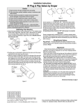
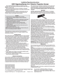
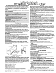
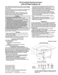
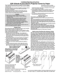
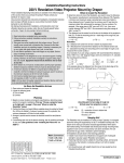
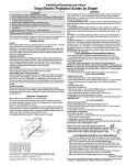
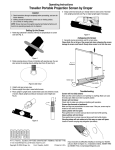
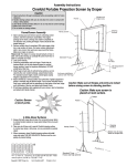
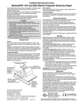
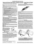
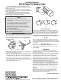
Installation Instructions
220V IR Plug & Play Salara by Draper
These Installation/Operating Instructions are available in the official
language of the country where you purchase the product. Please contact your
distributor to request a copy.
Vous pourriez demander les instructions d’installation et d’opération
traduises dans la langue officielle du pays ou vous achetez le produit. Veuillez
demander à votre distributeur.
Die Gebrauchsanweisung für Installation und Konstruktion sind in
der offiziellen Sprache des Landes, indem Sie das Produkt gekauft haben,
vorhanden. Fragen Sie die jeweilige Verkaufs-Abteilung.
Extrusions along
back of case
Caution
➀ Read instructions through completely before proceeding.
➁ Follow instructions carefully. Installation contrary to instructions invali-
Figure 2
dates warranty.
➂ Screen should be accessible for complete removal should fabric
become damaged or should other service be required.
➃ Screen should be installed level (using a carpenter’s level).
➄ Nothing should be fastened to screen dowel or viewing surface.
➅ Operating switch (es) packed separately in screen carton. Do not
discard with packing material.
➆ Screen operates on 220V AC, 50 Hz., 1 ph. current.
NOTE: Screen has been thoroughly inspected and tested at factory and
found to be operating properly prior to shipment.
Wall/Ceiling Flush Mounting
➀ Attach Mounting Brackets to wall or ceiling (see Fig. 1). The installer should
furnish screws, toggle bolts, molly bolts, nylon or lead anchors as required
by the mounting surface. Installer also needs to ensure the mounting
surface is reinforced sufficiently to support the screen. Brackets must be
level with each other.
Mounting
Bracket
Ceiling
Mounting
Bracket
1
2
Figure 3
3
Electrical Connections
Screen operates on 220V AC, 50 Hz., 1 ph. current. Screen shipped with
internal wiring complete. Junction box is located inside left endcap and cover
plate is secured to endcap with one screw. Screen is shipped with internal
wiring complete and control switch(es) fully boxed. No external wiring is
needed. unless connecting to RS232. Plug cord into standard 220V AC outlet.
All operating switches should be “OFF” before power is connected.
Operation
Screen is equipped with a handheld remote or 3-position operating switch
(see below). Three positions (up-off-down) permit operation to be stopped at
any point. Factory adjusted limit switches automatically stop screen when fully
down or fully up.
Wiring/Control Options:
11/2"
Wall
11/2"
Figure 1
➁ Plug the power cord (included if ordered) into the motor end of the screen
case (left end as the viewer sees the screen).
➂ Attach the screen by snapping the extrusions on the back of the case onto
the brackets. With the lower edge of the screen case tilted away from the
wall, engage the rib on top of the case with the slot on each bracket. Slide
the screen case along the brackets to adjust the screen location from left to
right if necessary (see Fig. 2). Once the case is in position, pivot the case
back toward the brackets until the lower edge of the case "snaps" into place
with the spring-loaded latch (see Fig. 3).
Plug & PlayTM —Provided with built-in IR receiver, handheld IR remote
control transmitter and 10' (3m) IEC cordset. No wiring necessary except to
connect to RS232.
Adjustments
Screen has been factory set and should not normally require further
adjustment. If you desire to change the “up” and “down” stopping positions,
follow the procedures below.
There are two holes in the left end cap (as seen from audience) for both limit
switch adjustments and neither is labled. The hole closest to the audience is
the up limit and the hole furthest from the audience is the down limit
“Down” limit switch: Down stopping position can be adjusted by turning
knob furthest from audience with a screw driver or hex wrench. Turning knob
counterclockwise will allow viewing surface to run farther down. Turning it
clockwise will reduce the amount of exposed viewing surface.
“Up” limit switch: You should never have to adjust this limit! If you do,
however, the Up stopping position can be adjusted by turning knob closest
to audience with a screw driver or hex wrench through the small grommet.
Turning knob counterclockwise will allow surface to run farther into screen
case. Turning it clockwise will allow viewing surface to stop farther out of
screen case.
CAUTION: Be sure all switches are in “off” position before adjusting limit
switches. Always be prepared to shut screen off manually when new
adjustment is being tested. Screen may be severely damaged if viewing
surface is allowed to run too far up or too far down.
Dimensional drawings on page 2
Copyright ©2007 Draper Inc. Form Salara-IRPlug&Play-220V_Inst07 Printed in U.S.A.
If you encounter any difficulty installing or servicing your Salara, call your dealer
or Draper, Inc., Spiceland, Indiana, (765) 987-7999 or fax (765) 987-7142.
Page 2 of 2
220V IR Plug & Play Salara by Draper
Dimensions
Floating Mounting Brackets
8 mm
Case Length
79
mm
35 mm
87 mm
97 mm
8
mm
129 mm
94 mm
8 mm
Viewing Surface
138 mm
Wiring Diagrams
Standard 220V AC IEC (no external wiring necessary)*
Green/Yellow
Line 1
Brown
Black
Blue
Motor/PCB Ground
(1) #10 Ring
Terminal on
each ground wire
Green/
Yellow
IEC Inlet
AC In Motor
N
L N Neu Dir Dir
Green
Brown
Blue
Motor
*In some countries, the Salara will not have an IEC cord. A cord will need to be obtained locally.
www.draperinc.com
(765) 987-7999