1
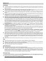
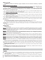
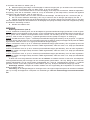
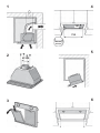
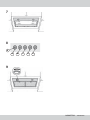
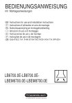
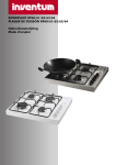
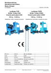
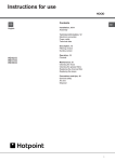
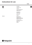
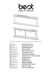
DHG397
INSTRUCTIONS FOR INSTALLATION AND USE
MONTAGE- UND GEBRAUCHSANWEISUNG
INSTRUCTIONS POUR L'INSTALLATION ET L’UTILISATION
ISTRUZIONI PER L'INSTALLAZIONE E L’USO
INSTRUCCIONES PARA INSTALACIÓN Y USO
INSTRUÇÕES DE INSTALAÇÃO Y UTILIZAÇÃO
AANWIJZING VOOR GEBRUIK EN INSTALLATIE
ENGLISH
WARNING
The distance between the supporting surface for the cooking worktop on the hob and the lower part of the hood
must be at least 65 cm. If the instructions for installation for the hob specify a greater distance, this has to be
taken into account.
The air collected must not be conveyed into a duct used to blow off smokes from appliances fed with an energy
other than electricity (central heating systems, thermosiphons, water-heaters, etc.).
Comply with the official instructions provided by the competent authorities in merit when installing the disposal
duct. In addition, exhaust air should not be discharged into a wall cavity, unless the cavity is designed for that
purpose.
The room must be well ventilated in case a hood and some other heat equipment fed with an energy other than
electricity (gas, oil, coal heaters, etc) operate at the same time.
The intake hood could create a vacuum indeed by extracting the air out the room. The vacuum should not exceed
0,04mbar. This prevents the head source to generate in-drawghts of gas that must be extracted out.
Check the data label inside the appliance; if the symbol ( ) is printed, read the following: this appliance
has such technical particularities that it belongs to class II insulation, therefore it must not be earthed.
The following warning is valid in the United Kingdom only: in case your cable is not furnished with a plug, read
the following instructions; as the colours of the wires in the mains lead of this appliance may not correspond with
the coloured markings identifying the terminals in your plug, proceed as follows: – the wire which is coloured blue
must be connected to the terminal which is marked with the letter N or coloured black; – the wire which is
coloured brown must be connected to the terminal which is marked with the letter L or coloured red. – terminal
of a three-pin plug.
Check the data label inside the appliance; if the symbol (
) is NOT printed, read the following:
ATTENTION: This appliance must be earthed. When making the electrical connections, check that the current
socket has a ground connection.
The following warning is valid in the United Kingdom only: in case your cable is not furnished with a plug, read
the following instructions; as the colours of the wires in the mains lead of this appliance may not correspond with
the coloured markings identifying the terminals in your plug, proceed as follows:
– the wire which is coloured green and yellow must be connected to the terminal in the plug which is marked
], or coloured green or green and yellow; – the wire which is coloured
with the letter E or by the earth symbol [
blue must be connected to the terminal which is marked with the letter N or coloured black; – the wire which is
coloured brown must be connected to the terminal which is marked with the letter L or coloured red.
When making the electrical connections, check that the voltage values correspond to those indicated on the data
plate inside the appliance itself. In case your appliance is not furnished with a non separating flexible cable and
has no plug, or has not got any other device ensuring omnipolar disconnection from the electricity main, with a
contact opening distance of at least 3 mm, such separating device ensuring disconnection from the main must
be included in the fixed installation. If your unit features a power lead and plug, position this so the plug is
accessible.
Always switch off the electricity supply before carrying out any cleaning or servicing operations on the appliance.
USE
Avoid using materials which could cause spurts of flame (flambées) near the appliance.
When frying, take particular care to prevent oil and grease from catching fire. Already used oil is especially
dangerous in this respect. Do not use uncovered electric grates.
To avoid possible risks of fire always comply with the indicated instructions when cleaning anti-grease filters and
when removing grease deposits from the appliance.
MAINTENANCE
Thorough servicing guarantees correct and long-lasting operation.
Any fat deposits should be removed from the appliance periodically depending on amount of use (at least every
2 months). Avoid using abrasive or corrosive products. To clean painted appliances on the outside, use a cloth
dipped in lukewarm water and neutral detergent. To clean steel, copper or brass appliances on the outside, it
is always best to use specific products, following the instructions on the products themselves. To clean the inside
of the appliance, use a cloth (or brush) dipped in denatured ethyl alcohol.
DESCRIPTION
The hood may be installed in the ducting version. Ducting version (Fig. 1): The hood aspirates the kitchen air
saturated with fumes and odours, passes it through the grease filters and expels it to the outside through an outlet
pipe. With this version the charcoal filters are not required.
The 2-motor version hood is only available for ducting version installation.
INSTALLATION
ATTENTION: 2 people are required for proper installation; the unit should be installed by a qualified
operator.
INSTALLATION IN DUCTING VERSION:
1. Before fixing, the disposal duct for air evacuation to the outside must be installed. Use an disposal duct with:
– minimum indispensable length; – minimum possible bends (maximum angle of bend: 90°); – certified material
(according to the State); – an as smooth as possible inside. It is also advisable to avoid any drastic changes in pipe
cross-section. We recommend using a 200 mm diameter pipe. For air evacuation to the outside, follow all the other
instructions given on the “Warnings” sheet.
2. You have purchased the 2-motor version (model shown in Fig. 2); you must fit the plastic flange using 4
screws (the screws are provided and are the 4 shortest ones).
3. Prepare a suitable power supply. For the electrical connection, follow all the other instructions on the
“Warnings” sheet.
4. Check to see the grease filters have been removed; if necessary, remove these by moving the catch (B)
and turning these outwards (Fig. 3).
5. Make a hole for housing the appliance (Fig. 4) in the bottom of the wall unit. The bottom of the wall unit must
have a thickness of between 15 and 20 mm.
6. Take 4 retention screws from the accessories bag. Fit the appliance in the hole made on the wall unit, first
positioning the rear part, so the flap on the back rests on the wall unit; next, slightly slide the appliance back, towards
the wall (Fig. 5).
Without leaving the appliance, secure this to the wall unit by means of the 4 screws (Fig. 6).
7. Proceed with final fitting, using the 4 screws (the longest ones); See Fig. 7.
8. Connect the disposal duct to the air evacuation pipe of the hood. Use a flexible pipe and lock it to the air
evacuation pipe of the hood with a metal hose clamp (pipe and clamp are not provided). Make the electrical
connections.
9. Refit the grease filters.
OPERATION
Controls (Fig. 8):
Button A: turns the lights on/off; every 30 hours of operation the corresponding pilot lamp (S) comes on to indicate
that the grease filters must be cleaned; every 120 hours of operation the corresponding pilot lamp (S) flashes to
indicate that the grease filters must be cleaned. To restart the hour counter (RESET), hold the button A pressed down
for about 1” (while the pilot lamp S is on).
Button B: drives the motor in first speed (the corresponding pilot lamp comes on); when holding it down for about 1”,
the motor cuts out; when pressing the button a second time (while the pilot lamp is on) , the TIMER is activated and
thus the motor stops after 5’ (the pilot lamp flashes).
Button C: drives the motor in second speed (the corresponding pilot lamp comes on); when pressing the button a
second time (while the pilot lamp is on) , the TIMER is activated and thus the motor stops after 5’ (the pilot lamp
flashes).
Button D: drives the motor in third speed (the corresponding pilot lamp comes on); when pressing the button a second
time (while the pilot lamp is on) , the TIMER is activated and thus the motor stops after 5’ (the pilot lamp flashes).
Button E: drives the motor in fourth speed (the corresponding pilot lamp comes on); when pressing the button a
second time (while the pilot lamp is on) , the TIMER is activated and thus the motor stops after 5’ (the pilot lamp
flashes).
Pay special attention to the grease filters: the grease filters must be cleaned approximately once every 30 hours
of operation (when the light button lamp comes on) - Fig. 8S). Wash out the filter using a neutral soap. Once the
cleaned filters are reinstalled, to reset the counter hold the light button pressed down for about 1” (Fig. 8A) while the
corresponding pilot lamp (S) is on.
Removing the grease filters: Remove the grease filters by moving fastener B and turning the filter outwards
(Fig. 3).
Lighting: to remove the halogen lamps, turn the locknut counter-clockwise (Fig. 9). Replace with the same type
of lamp. CAUTION: Do not handle glass bulb with bare hands.
DEUTSCH
HINWEIS
Der Mindestabstand zwischen der Topf-Trägerfläche auf der Kochmulde und dem unteren Teil der Abzughaube
muss 65 cm betragen. Geben die Installationsanleitungen der Kochmulde einen höheren Abstand an, so ist
dieser einzuhalten.
Ein Anschluss der Abluftleitungen an Verbrennung-sabgaskamine (zum Beispiel Zentralheizung, Heizgeräte,
Badezimmeröfen usw.) ist nicht gestattet.
In jedem Fall sind bei der Ableitung der Abluft die behördlichen Vorschriften zu beachten. Desweiteren darf die
en de filters naar buiten te draaien (afb. 3).
5. Maak de opening die nodig is om de afzuigkap in onder te brengen (afb. 4) in de bodem van het bovenkastje.
De bodem van het bovenkastje moet een dikte tussen 15 en 20 mm hebben.
6. Neem de 4 schroeven die dienen voor de bevestiging uit het zakje met accessoires. Plaats het apparaat in
de opening, eerst aan de achterkant, zodat de vin op de achterkant op het kastje steunt; verschuif het apparaat
vervolgens iets naar achteren, naar de muur (afb. 5).
Zet het apparaat zonder het los te laten vast aan het bovenkastje met behulp van de 4 schroeven (afb. 6).
7. Ga over tot de definitieve bevestiging, door nog 4 schroeven aan te brengen (de langere). Zie afb. 7.
8. Verbind de luchtafvoerpijp met de luchtafvoeropening van de kap; gebruik een buigzame slang en zet deze
met een metalen bandje aan de luchtuitlaat van de afzuigkap vast (slang en bandje worden niet meegeleverd). Breng
de elektrische aansluiting tot stand.
9. Monteer de vetfilters weer.
WERKING
Bedieningselementen (afb. 8):
Toets A: schakelt de verlichting in/uit; om de 30 bedrijfsuren gaat het betreffende lampje (S) branden om aan te geven
dat de vetfilters schoongemaakt moeten worden; om de 120 bedrijfsuren gaat het betreffende lampje (S) branden om
aan te geven dat de vetfilters schoongemaakt moeten worden. Om de telling van de uren weer te laten starten
(RESET), moet de toets A ongeveer 1” ingedrukt gehouden worden (terwijl het lampje S in werking is).
Toets B: schakelt de motor in op de 1e snelheid (het betreffende lampje gaat branden); als hij ongeveer 1” ingedrukt
gehouden wordt, gaat de motor uit; door nogmaals op de toets te drukken (terwijl het lampje brandt) wordt de TIMER
ingeschakeld, zodat de motor na 5’ stopt (het betreffende lampje knippert).
Toets C: schakelt de motor in op de 2e snelheid (het betreffende lampje gaat branden); door nogmaals op de toets
te drukken (terwijl het lampje brandt) wordt de TIMER ingeschakeld, zodat de motor na 5’ stopt (het betreffende
lampje knippert).
Toets D: schakelt de motor in op de 3e snelheid (het betreffende lampje gaat branden); door de toets nogmaals in
te drukken (terwijl het lampje brandt) wordt de TIMER ingeschakeld, zodat de motor na 5’ stopt (het betreffende
lampje knippert).
Toets E: schakelt de motor in op de 4e snelheid (het betreffende lampje gaat branden); door de toets nogmaals in
te drukken (terwijl het lampje brandt) wordt de TIMER ingeschakeld, zodat de motor na 5’ stopt (het betreffende
lampje knippert).
Er dient met name zorg besteed te worden aan de vetfilters: de vetfilters moeten na elke circa 30 bedrijfsuren
schoongemaakt worden (als het lampje van de verlichtingstoets gaat branden - afb. 8S). Reinig de filters met een
neutraal afwasmiddel. Als de schone filters teruggeplaatst zijn, moet de verlichtingstoets ongeveer 1” ingedrukt
gehouden worden om de telling opnieuw te laten starten (afb. 8A), terwijl het betreffende lampje (S) brandt.
Demontage vetfilters: verwijder de metalen vetfilters door de vergrendeling B te verplaatsen en het filter naar
buiten te draaien (afb. 3).
Verlichting: om de halogeenlampjes te vervangen moet u de ringmoer tegen de wijzers van de klok in losdraaien
(afb. 9). Vervang de lampjes door exemplaren van hetzelfde type. LET OP: raak het lampje niet met blote handen
aan.
1
4
381
725
min 15
max 20
5
2
Ø 200
3
6
7
8
S
A
B
C
D
E
9
04306779/1 - CK2000de