1
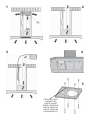
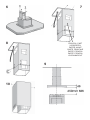
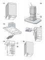
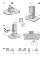
Guide d’utilisation
Instructions for installation and use
Montage- und gebrauchsanweisung
Istruzioni per l'installazione e l’uso
Instrucciones para instalación y uso
Instruções de instalação y utilização
Aanwijzing voor gebruik en installatie
DHD493XE1 - DHD496XE1
les mêmes opérations mais à l’inverse.
Eclairage: pour remplacer les lampes halogènes, ouvrez le couvercle en faisant levier grâce aux fissures prévues
à cet effet (Fig. 21). Remplacez-les par des lampes ayant les mêmes caractéristiques. ATTENTION: Ne pas toucher
l’ampoule à main nue. Si, après le remplacement des lampes halogènes ces dernières ne fonctionnement pas, faire
refroidir l’appareil, puis couper l’alimentation pendant quelques secondes.
ENGLISH
WARNING
The distance between the supporting surface for the cooking worktop on the hob and the lower part of the
hood must be at least 65 cm. If the instructions for installation for the hob specify a greater distance, this
has to be taken into account.
The air collected must not be conveyed into a duct used to blow off smokes from appliances fed with an
energy other than electricity (central heating systems, thermosiphons, water-heaters, etc.).
Comply with the official instructions provided by the competent authorities in merit when installing the disposal
duct. In addition, exhaust air should not be discharged into a wall cavity, unless the cavity is designed for
that purpose.
The room must be well ventilated in case a hood and some other heat equipment fed with an energy other
than electricity (gas, oil, coal heaters, etc) operate at the same time.
The intake hood could create a vacuum indeed by extracting the air out the room. The vacuum should not
exceed 0,04mbar. This prevents the head source to generate in-drawghts of gas that must be extracted out.
Check the data label inside the appliance; if the symbol ( ) is printed, read the following: this appliance
has such technical particularities that it belongs to class II insulation, therefore it must not be earthed.
The following warning is valid in the United Kingdom only: in case your cable is not furnished with a plug,
read the following instructions; as the colours of the wires in the mains lead of this appliance may not
correspond with the coloured markings identifying the terminals in your plug, proceed as follows: – the wire
which is coloured blue must be connected to the terminal which is marked with the letter N or coloured black;
– the wire which is coloured brown must be connected to the terminal which is marked with the letter L or
coloured red. – terminal of a three-pin plug.
Check the data label inside the appliance; if the symbol (
) is NOT printed, read the following:
ATTENTION: This appliance must be earthed. When making the electrical connections, check that the current
socket has a ground connection.
The following warning is valid in the United Kingdom only: in case your cable is not furnished with a plug,
read the following instructions; as the colours of the wires in the mains lead of this appliance may not
correspond with the coloured markings identifying the terminals in your plug, proceed as follows:
– the wire which is coloured green and yellow must be connected to the terminal in the plug which is marked
], or coloured green or green and yellow; – the wire which
with the letter E or by the earth symbol [
is coloured blue must be connected to the terminal which is marked with the letter N or coloured black; –
the wire which is coloured brown must be connected to the terminal which is marked with the letter L or coloured
red.
When making the electrical connections, check that the voltage values correspond to those indicated on the
data plate inside the appliance itself. In case your appliance is not furnished with a non separating flexible
cable and has no plug, or has not got any other device ensuring omnipolar disconnection from the electricity
main, with a contact opening distance of at least 3 mm, such separating device ensuring disconnection from
the main must be included in the fixed installation. If your unit features a power lead and plug, position this
so the plug is accessible.
Always switch off the electricity supply before carrying out any cleaning or servicing operations on the
appliance.
USE
Avoid using materials which could cause spurts of flame (flambées) near the appliance.
When frying, take particular care to prevent oil and grease from catching fire. Already used oil is especially
dangerous in this respect. Do not use uncovered electric grates.
To avoid possible risks of fire always comply with the indicated instructions when cleaning anti-grease filters
and when removing grease deposits from the appliance.
MAINTENANCE
Thorough servicing guarantees correct and long-lasting operation.
Any fat deposits should be removed from the appliance periodically depending on amount of use (at least
every 2 months). Avoid using abrasive or corrosive products. To clean painted appliances on the outside,
use a cloth dipped in lukewarm water and neutral detergent. To clean steel, copper or brass appliances on
the outside, it is always best to use specific products, following the instructions on the products themselves.
To clean the inside of the appliance, use a cloth (or brush) dipped in denatured ethyl alcohol.
DESCRIPTION
The hood may be installed in the filtering version, in the ducting version or in the version with an external motor.
Filtering version (Fig. 1): The hood aspirates the kitchen air saturated with fumes and odours, purifies it through
the grease filters and charcoal filters and returns clean air into the room. WARNING: When using filtering hoods,
both charcoal filters and an air baffle must be used; located in the upper part of the pipe, this baffle recycles
the air to the environment (Fig. 1A). For constant efficiency, the charcoal filters must be replaced periodically.
Ducting version (Fig. 2): The hood aspirates the kitchen air saturated with fumes and odours, passes it through
the grease filters and expels it to the outside through an outlet pipe. With this version the charcoal filters are
not required.
Version with an external motor (Fig. 3): the hood is connected to a vacuum motor set outside the kitchen, or
outside the building; the motor aspirates the kitchen air saturated with fumes and odours making it go through
the anti-grease filters of the hood, then through the air disposal duct to make it go outside.
If you chose to install this version of the hood, you have to buy it already fit for this installation, which means
without the motor inside; moreover you have to buy a vacuum motor (only use vacuum units suggested in the
original catalogue). With this version the charcoal filters are not required.
Decide from the outset on the type of installation (filtering, ducting or with an external motor). For greater
efficiency, we recommend you install the hood in the ducting version or in the version with an external motor (if
possible). Attention: you can chose to install the hood with an external motor only if you have bought a hood
already planed for this version.
INSTALLATION
ATTENTION: Three people are required for proper installation; the unit should be installed by a qualified operator.
Also follow carefully each step of the assembly instructions, and once installation has been completed, make sure
that the hood is firmly secured in place.
Remove the grease filters before proceeding with the assembly instructions. This will make the appliance easier to handle.
1. Removal of grease filters: Fig. 4: pull the handle outside and unlock the filter.
INSTALLATION IN DUCTING VERSION:
Before fixing, the outlet pipe for air evacuation to the outside must be installed. Use an outlet pipe with: – minimum
indispensable length; – minimum possible bends (maximum angle of bend: 90°); – certified material (according to the State);
– an as smooth as possible inside. It is also advisable to avoid any drastic changes in pipe cross-section (recommended
diameter: 150 mm). For air evacuation to the outside, follow all the other instructions given on the “Warnings” sheet.
Prepare the power supply within the telescopic chimney (for the electrical connection, follow all the other instructions
on the “Warnings” sheet).
2. Using the special drilling template, drill the holes for fixing to the ceiling on the vertical side of your hob. Carefully
observe all the indications for final positioning of the apparatus. Take into account that one of the template axes must
correspond to the axis of the hood controls. Fix the bracket to the ceiling using the screws and screw anchors provided
(Fig. 5). Be careful, because the position of the bracket determines the final position of the apparatus.
3. Assemble the plate of the electrical system fixing it with 3 screws and 2 metal washers (Fig. 6).
4. Fix the telescopic structure to the bracket by means of 4 screws (provided), running the air evacuation pipe through
the telescopic structure and the electric power cable through the special hole in the bracket (Fig. 7). Adjust the height
of the telescopic structure by means of the four retaining screws C (Fig. 8), taking into account that the height of the
hood is 48 mm and that the distance between the hood and the hob must be at least 650 mm (Fig. 9).
5. Take the upper flue (with the slots) and fit it on the telescopic structure with the slots facing downwards; fit the
flue to the bracket with 2 screws (Fig. 10).
6. Take the lower flue and fit it in the same manner as before; slide it to the top and stop it in that position using a
screw inserted in the hole of the upper flue as a catch (Fig. 11).
7. Fit the hood to the telescopic structure by means of 4 screws (provided) – Fig. 12.
8. Through openings D (Fig. 12) fix the air evacuation pipe to flange.
9. Make the electrical connection by means of the power cable.
10. Remove the screw used as catch and slide the lower flue downwards, placing it gently on the apparatus.
11. Remove the charcoal filter from its case (Fig. 13).
Installation is now complete and the grease filters can be reassembled.
INSTALLATION IN FILTERING VERSION:
Prepare the power supply within the telescopic flues (for the electrical connection, follow all the other instructions
on the “Warnings” sheet).
2. Using the special drilling template, drill the holes for fixing to the ceiling on the vertical side of your hob. Carefully
observe all the indications for final positioning of the apparatus. Take into account that one of the template axes must
correspond to the axis of the hood controls. Fix the bracket to the ceiling using the screws and screw anchors provided
(Fig. 5). Be careful, because the position of the bracket determines the final position of the apparatus.
3. Assemble the plate of the electrical system fixing it with 3 screws and 2 metal washers (Fig. 6).
4. Fix the telescopic structure to the bracket by means of 4 screws (provided), running the electric power cable through
the special hole in the bracket (Fig. 7). Adjust the height of the telescopic structure by means of the four retaining screws
C (Fig. 8), taking into account that the height of the hood is 48 mm and that the distance between the hood and the hob
must be at least 650 mm (Fig. 9).
5. Insert the air baffle (F) in the structure (Fig.14).
6. Through the openings E (Fig.15), fit the flange (G) to the baffle (F) locking it with a turning movement. Fix a flexible
pipe to the flange (G) for air evacuation.
7. Take the upper flue (with the slots) and fit it on the telescopic structure with the slots facing upwards; fit the flue
to the bracket with 2 screws (Fig. 16).
8. Take the lower flue and fit it in the same manner as before; slide it to the top and stop it in that position using a
screw inserted in the hole of the upper flue as a catch (Fig. 11).
9. Take the riduction (L) and assemble it onto the flange (Fig. 17).
10. Fit the hood to the telescopic structure by means of 4 screws (provided) – Fig. 18.
11. Fix the air evacuation pipe onto the reduction (L) - Fig. 18.
12. Make the electrical connection by means of the power cable.
13. Remove the screw used as catch and slide the lower flue downwards, placing it gently on the apparatus.
Installation is now complete and the grease filters can be reassembled.
INSTALLATION IN VERSION WITH AN EXTERNAL MOTOR:
Before fixing the hood the air evacuation pipe running from the hood to the intaking motor should be ready.
Use an air evacuation pipe with: – minimum indispensable length; – minimum possible bends (maximum angle of
bend: 90°); – certified material (according to the State); – an as smooth as possible inside. It is also advisable
to avoid any drastic changes in pipe cross-section (recommended diameter: 150 mm). For air evacuation to the
outside, follow all the other instructions given on the “Warnings” sheet.
Prepare the power supply within the telescopic flue (for the electrical connection, follow all the other instructions
on the “Warnings” sheet).
Refer to the instructions for the ducting version (see point 2, 3, 4, 5, 6, 7, 8), then continue with the
instructions below.
9. Connect the hood to the external motor using the special terminal block (Fig. 19): remove wire clamp A
and lid B from the wiring junction box; fix the connecting wire of the external motor to terminal C; then replace
wire clamp A and lid B on the wiring junction box; the other end of the wire is secured to the terminal block on
the external motor.
10. Make the electrical connection by means of the power cable.
11. Remove the screw used as catch and slide the lower flue downwards, placing it gently on the apparatus.
12. Remove the charcoal filter from its case (Fig. 13).
Installation is now complete and the grease filters can be reassembled.
OPERATION
CONTROLS (Fig. 20):
Key A : Turns the lights on/off.
Key B : Reduces and increases lighting intensità.
Key C : reduces the motor speed until reaching minimum. If pressed for about 2", it stops the motor and storse the
speed.
Key D : drives the motor (calling the last speed used) and increases the speed until reaching maximum.
L Display:
- signals the running speed.
- signals the filter alarm (with motor off) by displaying the central segment for 30".
- signals Timer activation with a flashing number.
Key E : activates the TIMER (when the motor is running), so that the hood stops automatically after 5'. Also Zero-sets
hour metering when the Filter Alarm is active (motor OFF).
FILTER ALARM: Displayed for 30" when the motor is off:
After 30h of operation, the central segment lights up on the display; It indicates that the grease filters need to be
cleaned.
After 120h of operation, the central segment flashes on the display; It indicates that the grease filters need to be
cleaned and the charcoal filters replaced.
After cleaning the grease filters (and/or replacing the charcoal filters), restart the hour counter (RESET) by pressing
the key E during display of the filter alarm.
Grease filters: special attention must be given to the grease filters which must be periodically cleaned, whenever
the filter alarm trips. For instructions of the filter Alarm, refer to the Controls paragraph. Remove the filters as shown in
para. 1 and wash with neutral detergent.
Charcoal filters: if the filtering version appliance is used, the charcoal filters will have to be periodically replaced
when the filter alarm trips. For instructions on the filter Alarm, refer to the Controls paragraph. Removing the charcoal filter/
s: first of all, remove the grease filters; push the catch inwards (Fig. 13) and remove the charcoal filter from its case.
Reposition a new charcoal filter of the same type inverting the operations.
Lighting: to change the halogen bulbs open the cover levering from the proper slots (Fig. 21). Replace with bulbs
of the same type. CAUTION: Do not handle glass bulb with bare hands. If, after replacing the halogen lights, these
fail to work, allow the appliance to cool and then interrupt power for a few seconds.
DEUTSCH
HINWEIS
Der Mindestabstand zwischen der Topf-Trägerfläche auf der Kochmulde und dem unteren Teil der Abzughaube
muss 65 cm betragen. Geben die Installationsanleitungen der Kochmulde einen höheren Abstand an, so ist
dieser einzuhalten.
Ein Anschluss der Abluftleitungen an Verbrennung-sabgaskamine (zum Beispiel Zentralheizung, Heizgeräte,
Badezimmeröfen usw.) ist nicht gestattet.
In jedem Fall sind bei der Ableitung der Abluft die behördlichen Vorschriften zu beachten. Desweiteren darf
die Abluft nur dann durch ein Loch in der Wand geleitet werden, wenn dieses für diesen Zweck bestimmt ist.
Achtung! Bei gleichzeitigem Betrieb einer Abluft-Dunstabzugshaube und einer raumluftabhängigen Feuerstätte
(wie z. B. gas-, öl- oder kohlebetriebene Heizgeräte, Durchlauferhitzer, Warmwasserbereiter) ist Vorsicht
geboten, da beim Absaugen der Luft durch die Dunstabzugshaube dem Aufstellraum die Luft entnommen wird,
die die Feuerstätte zur Verbrennung benötigt. Ein gefahrloser Betrieb ist möglich, wenn bei gleichzeitigem
Betrieb von Haube und raumluftabhängiger Feuerstätte im Aufstellraum der Feuerstätte ein Unterdruck von
höchstens 0,04 mbar erreicht wird und damit ein Rücksaugen der Feuerstättenabgase vermieden wird. Daher
den Raum mit Lüftungsanschlüssen versehen, die einen konstanten Zustrom von Frischluft gewährleisten.
Das Typenschild im Innern des Geräts kontrollieren: Den folgenden Anweisungen folgen, falls das Symbol
(
) erscheint; dieses Gerät weist konstruktive technische Details auf, die unter die Isolierungsklasse
II fallen und deshalb muss es nicht geerdet werden.
Das Typenschild im Innern des Geräts kontrollieren: den folgenden Anweisungen folgen, falls das Symbol
(
) NICHT erscheint; ACHTUNG: dieses Gerät muss geerdet werden. Beim elektrischen Anschluss
sicherstellen, dass die Steckdose eine Erdung aufweist.
Beim elektrischen Anschluss muss überprüft werden, ob die Spannungswerte des Stromnetzes mit den Werten
auf dem im Innern des Gerätes angebrachten Typenschilds übereinstimmen. Falls Ihr Gerät nicht mit einem
fest angeschlossenem Kabel mit Stecker oder einer sonstigen Vorrichtung, die eine allpolige Unterbrechung
mit einer Kontaktöffnung von mindestens 3 mm versehen ist, so müssen die entsprechenden Trennvorrichtungen
bei der festen Installation vorgesehen werden. Das Gerät so aufstellen, dass der Stecker zugänglich ist, falls
Ihr Gerät mit einem Netzkabel mit Stecker ausgestattet ist.
Vor jeder Reinigungs- oder Wartungsarbeit muss das Gerät vom Stromnetz getrennt werden.
GEBRAUCH
In der unmittelbaren Nähe des Geräts die Benutzung von flammenerzeugenden Materialien (Flambieren)
vermeiden.
Beim Frittieren besonders auf die Brandgefahr achten, die durch Öl und Fette verursacht wird. Besonders
gefährlich ist die Entflammbarkeit von bereits benutztem Öl. Keine offenen Elektrogrills verwenden.
Zur Vermeidung einer möglichen Brandgefahr die Anweisungen zur Reinigung der Fettfilter und zur Entfernung
eventueller Fettablagerungen auf dem Gerät beachten.
WARTUNG
Nur eine sorgfältige Pflege garantiert auf Dauer eine gute Leistung und Funktion des Geräts.
Die Entfernung eventueller Fettablagerungen vom Gerät erfolgt in regelmäßigen Abständen in Abhängigkeit von
der Benutzung (zumindest alle zwei Monate). Die Verwendung von scheuernden oder korrosiven Produkten
vermeiden. Für die äußere Reinigung von lackierten Geräten ein mit lauwarmen Wasser und Neutralreiniger
angefeuchtetes Tuch verwenden; für die äußere Reinigung der Geräte aus Stahl, Kupfer und Messing wird die
Verwendung von Spezial-produkten empfohlen, wobei die auf dem Produkte angegebenen Anweisungen zu
beachten sind; für die innere Reinigung der Geräte einen in denaturalisierten Äthylalkohol eingetauchten Lappen
(oder Pinsel) verwenden.
1
2
3
4
5
FRONTAL PART
VORDERTEIL
PARTIE AVANT
PARTE FRONTALE
PARTE FRONTAL
PARTE FRONTAL
VOORAANZICHT
6
7
8
FRONTAL PART
VORDERTEIL
PARTIE AVANT
PARTE FRONTALE
PARTE FRONTAL
PARTE FRONTAL
VOORAANZICHT
9
10
11
12
13
14
15
16
17
18
19
C
A
B
20
21