1
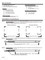
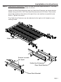
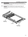
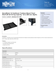
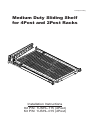
Patent(s) Pending
Medium Duty Sliding Shelf
for 4Post and 2Post Racks
Installation Instructions
Kit P/N: 1USHL-115 (4Post)
Kit P/N: 1USHL-015 (2Post)
Kit Contents
(1) Partially Assembled Shelf
(1) Anti-Slip Mat 12”x15”
(1) 50” Velcro Strap for Cable Arm
Assembly Hardware Kit:
(4)
(6)
(6)
(3)
Brackets:
(2)
(1)
(1)
(1)
(2)
(2)
Rear Rack Brackets
Removable Front Stop
Adjustable Rear Stop
Arm Extension Bracket
Cable Management Arms
Arm Attachment Brackets
8-32 x 3/8” Flat Head Screws
8-32 x 3/8” Pan Head Screws
8-32 Nuts
2.5” Clevis Pins & Cotter Pins
(for Cable Mgmt)
Rack Mount Hardware Kit:
(8)
(8)
(8)
(8)
12-24 x 1/2” Screws
10-32 x 1/2” Screws
12-24 Square Nuts
10-32 Cage Nuts
1USHL-015 Adds:
(2) 3U Tall 2Post Brackets (see Page 8)
(12) 12-24 Bolts for Relay Racks
Installation Instructions
Step 1. Mounting Depth: Measure the “Mounting-Depth” for your rack from the front of
the “Front-Mounting-Surface” to the back of the “Back-Mounting-Surface”. Go to
Step 2 or Step 3 based on the measurement.
MOUNTING DEPTH
REAR
FRONT
Double 2Post
REAR
FRONT
4Post Cabinet
MOUNTING DEPTH
Step 2. 23.5” to 31.5”: The Rear Rack Brackets will be installed as shown below for this
“Mounting Depth” range.
“Mounting Depth” 23.5” – 31.5”
Step 3. 15.5” to 23.5": The Rear Rack Brackets will be installed as shown below for this
“Mounting Depth” range.
“Mounting Depth” 15.5” - 23.5”
Reversed Rear Rack Bracket
Page 2
Installation Instructions
Step 4. Rear Bracket Attachment: Move the slide rails back approximately 8". You may
need to loosen the thumb screws to do this.
Attach the Rear Rack Brackets and the Cable Arm Extension as shown below.
Attach using (4) 8-32 x 3/8” Pan Head Screws and (4) 8-32 Nuts. The screws
should be located in the slots as far apart from one another as possible (see
below). Tighten all screws.
The Cable Arm Extension can be attached to the right or left, based on your
cabling needs.
Slide Rails Back
Screws Located
Far Apart
Cable Arm Extension
Rear Rack Bracket
Rear Rack Bracket
Page 3
Installation Instructions
Step 5. Cable Management: Attach the two Arm Attachment Brackets to the back of the
Shelf as shown below. Attach using (4) 8-32 x 3/8” flat head screws. Tighten all
screws.
Note: Cable management may be installed on opposite side.
Arm Attachment Bracket
Arm Attachment Bracket
Page 4
Installation Instructions
Step 6. Cable Arms: Attach the two Cable Management Arms using three 2.5”
clevis pins.
Note: Cable management may be installed on opposite side.
Clevis Pins
& Cotter Pins
Clevis Pin &
Cotter Pin
Page 5
Installation Instructions
Step 7. Rack Installation: Attach the front and back of the Shelf to the rack. Hardware is
provided for square hole racks (12-24 Screw + Cage Nut), threaded hole racks
(10-32 or 12-24 screws), or unthreaded hole racks (12-24 screws and nuts).
Tighten all screws.
Special Note: The right-hand and left-hand thumb screws must be
engaged and must be tight before tightening the front rack mount
screws.
Front View
Tighten Thumb Screws First
Tighten Rack Screws Second
Rear View
Page 6
Installation Instructions
Step 8. Server Installation: Pull the shelf out of the rack until it stops. Attach the
Removable Front Stop (shown below) to the front of the shelf. Place the AntiSlip Mat on the shelf. Put the server or other equipment on the shelf and move
forward against the Front Stop.
Step 9. Rear Stop: Attach the Adjustable Rear Stop tight against the back of the
equipment to keep the equipment from moving on the shelf. Attach the
Adjustable Rear Stop to the shelf using (2) 8-32x1/2” Pan Head Screws and
(2) 8-32 Nuts.
Adjustable
Rear Stop
Anti-Slip
Removable
Front Stop
Page 7
Installation Instructions
2Post Installations (require the 1USHL-015 kit).
Center Mount
Flush Mount
Warranty Statement
Innovation First, Inc. warrants our products against defects in material and workmanship for a
period of one (1) year from the date of purchase. Innovation First, Inc. liability shall be limited to
repairing or replacing, at our option, any defective product.
E
61