1
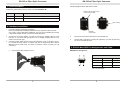
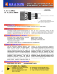
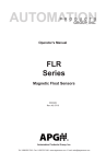
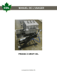
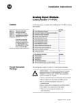
RS-232 to Fiber Optic Converter
EX-6300MM / SM
DB9 (Male) to DB9 (Male) Wiring
DB9 (Converter)
DB9 (Serial Device)
1 NC
1 DCD
2 RXD
2 RXD
3 TXD
3 TXD
4 NC
4 DTR
5 GND
5 GND
6 NC
6 DSR
7 NC
7 RTS
8 NC
8 CTS
RS-232 to Fiber Optic Converter
1. Introduction
Thank you for purchasing this RS232 to Fiber Optic Converter. It is designed to
extend RS232 signals over optical fiber. It provides the most versatile connection
possible between any asynchronous RS232 equipments using fiber optic cable.
The optical fiber isolates the data signals from ground potential, ground loops and
provides EMI/RFI protection. There are 2 models, single-mode and multi-mode.
The multi-mode converter is used to extend serial transmission distance up to
2Km. The single-model converter extends up to 40Km.
Features:
√
√
√
√
√
√
√
6. Specifications
Type
Connectors:
Specifications
DB9 Male
SC Optic Duplex
RS-232 Signals:
TXD, RXD, GND
Baud Rate:
Up to 921.6Kbps
Power Requirement:
12V / 35mA max.
Surge Protection:
15KV ESD
Distance:
Multi-Mode 2Km
√
√
√
√
Provides 1 RS232 Port over Fiber Optic
Provides 1 RS232 DB9 Male Connector
Fiber Optic: SC, Multi Mode, 850nm, Duplex
SC, Single Mode, 1310nm, Duplex
RS232 Baud Rate from 300bps to 921.6Kbps
Protects Against Electrical Interference or Chemical Corrosion
Extends RS232 Transmission up to 2Km, multi-mode (or 40Km, single-mode
Distance
15KV ESD Protection for Serial Port Signals
Powered by Serial Connector or External DC Jack
Provides both Wall Mounting and DIN RAIL Kits
Compact Size
2. Layout
RS232 DB9 male connector
Single-Mode 20Km
Wave:
Multi-Mode 850nm
Fiber TX LED
Fiber RX LED
Single-Mode 1310nm
Operating Temperature: 00 to 600C (320 to 1400F)
Operating Humidity
5 to 95% RH
Storage Temperature
-200 to 850C (-40 to 1850F)
DIN RAI Mounting Kit
Fiber Optic
Transceiver
4
12V DC Jack
1
RS-232 to Fiber Optic Converter
RS-232 to Fiber Optic Converter
Checking Single-mode or Multi-mode models:
3. LED Description
There are 2 green LEDs on the top of the Converter: Windows XP
Stickers indicate single mode
or multi-mode models
LED
Color
Function
TX
Green
Blinking when the Fiber is sending data
RX
Green
Blink when the Fiber is receiving data
Wall mounting Kit
4. Hardware Installation
1. Use static electricity discharge precautions.
Remove possible static discharge potential from any objects that the Converter
may come in contact with before installation. This can be accomplished by touching
a bare metal chassis rail after you have turned off the power.
2. Connect the AC power adapter, you need a 12V DC type adapter, either a screw
lock type or non screw lock type will do. The AC adapter supplied with the Converter is a screw lock type.
3. Connecting Fiber Cable: Please remove the protection cover on the fiber connector, connect the fiber cable to it. Please note that the single-mode fiber cable is
different from the multi-mode. You have to check the correct Converter you are
connecting.
•
Removing the fiber protection cover:
DIN RAIL
mounting Kit
4.
Connect the Converter’s serial port to your serial device.
5.
Use the Wall or DIN RAIL mounting Kit (optional) if you want to place the product on the industrial DIN RAIL.
5. RS-232 Male DB9 Pin Assignments and Cable
DB9-Male Pin Assignment:
Serial 9 Pin male connector:
Pin
Signal
Pin
Signal
Pin
Signal
1
NC
4
NC
7
NC
2
RXD
5
GND
8
NC
3
TXD
6
NC
9
NC
NC = No connection
2
3