Download Sony YTICB45
Transcript
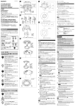
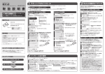
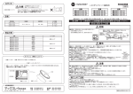
3-113-377-05 (1) A Removing the In-Ceiling Bracket 概要 YT-ICB45は、ネットワークカメラまたはカラービデオカメラ用の天井埋め込 み金具です。カメラ本体を天井に埋め込んで使用する場合や、石膏ボードな ど天井の材質がもろくネジがききにくい場合に使用します。 この取付説明書のカメラのイラストは、SNC-DF50 シリーズを使用していま す。 In-Ceiling Bracket 半球嵌入安装支架 取り付けかた 取付説明書 位置/Position/Position Installation Instructions Manuel d’installation Manual de instalación Installationsanleitung Istruzioni per l’installazione A B C 1 モデル/Model/Modèle SNC-DF50N, DF50P, DF80N, DF80P SSC-CD75, CD75P, CD77, CD77P SSC-CD79, CD79P 2 SNC-DS10, DS60, DM110, DM160 SSC-CD45, CD45P, CD47P, CD49, CD49P 電気製品は、安全のための注意事項を守らないと、火災や人 身事故になることがあります。 この取付説明書には、事故を防ぐための重要な注意事項と製品の取り扱い かたを示しています。この取付説明書をよくお読みのうえ、製品を安全に お使いください。お読みになったあとは、いつでも見られるところに必ず 保管してください。 カメラ本体からドームケースをはずす。 ◆ 詳しくは、カメラの設置説明書や取扱説明書をご覧ください。 上記以外のモデルはカメラの設置説明書や取扱説明書をご覧下さい。 For the model not listed above, refer to the Installation Manual or the Operating お買い上げいただきありがとうございます。 天井にφ 229 ± 2 mm の穴を開ける。 付属のテンプレートをご利用ください。 テンプレートの 4 か所の長穴は、カメラの中心位置を決めるときにご利 用ください。 Instrustions of the camera. Si le modèle n’est pas indiqué dans la liste ci-dessus, reportez-vous au Manuel d’installation ou au Mode d’emploi de la caméra. 3 4 5 B カメラにケーブルを接続する。 カメラの型に応じて、ブラケット固定位置をセットする: 左右の金具の ネジ(各2本)をはずし、取り外したネジを、表に示す正しいネジ穴に 固定する。(図 A ) 本機に付属の M4 ネジを使って、天井埋め込み金具をカメラ本体、また はカメラに付属のブラケットに取り付ける。(図 B C ) ◆ 詳しくは、カメラの設置説明書や取扱説明書をご覧ください。 ご注意 • 本機の穴の中心と、カメラの底面またはカメラに付属のブラケット の中心を合わせて取り付けてください。中心がずれていると、カ バーが取り付けられない場合があります。 6 YT-ICB45 2007 Sony Corporation Printed in China 金具の左右にある固定板が縦になっていること(工場出荷状態)を確認 してから、カメラと金具が一体になったものを天井の穴に組み込む。 (図 D) 7 金具の左右のネジを締め、金具で天井を挟む。 ネジを締めると、縦になっていた固定板が外側へ回転して開きます。さ らにネジを締めると固定板が下がって天井を挟みます。(図 E ) 固定板が天井をしっかり挟んでいることを確認してください。 ご注意 ネジを締めるときは、1.47N・m(15 kgf・cm)以下のトルクで締め てください。 あまり強く締めると埋め込み金具が壊れることがあります。 安全のために 8 M4ネジ / M4 screws / Vis M4 ソニー製品は安全に充分配慮して設計されています。しかし、電気製品は、 C カメラのスリットカバーを取りはずして、カメラの撮影方向や画角を調 整する。 調整が終わったらスリットカバーを元どおり取り付けます。 ◆ 詳しくは、カメラの設置説明書や取扱説明書をご覧ください。 まちがった使いかたをすると、火災や感電などにより死亡や大けがなど人身 9 事故につながることがあり、危険です。事故を防ぐために次のことを必ずお ドームケースをカメラ本体に取り付ける。 ◆ 詳しくは、カメラの設置説明書や取扱説明書をご覧ください。 守りください。 10 本機のカバーを取り付ける。(図 F ) • 安全のための注意事項を守る。 警告表示の意味 カバー内側の突起が金具にはめ込まれるようにカバーを回しながら取り 付け、カバーのネジ 2 本を締めます。 注意を促す記号 天井埋め込み金具のはずしかた この取付説明書および製品では、次のよ カバーのネジ 2 本をゆるめ、カバーを回して取りはずします。金具の左右の 固定板が縦になるまで左右のネジをゆるめてから、金具とカメラをはずしま す。 うな表示をしています。 表示の内容をよ く理解してから本文をお読みください。 M4ネジ / M4 screws / Vis M4 D この表示の注意事項を守らないと、火災 や感電などにより死亡や大けがなど 天井 / 直径φ 227 ∼ 231 の穴 / 天井 / 1 / Ceiling / φ 227 to 231 (9 to 9 /8) hole Ceiling / 1 φ 227 à 231 (9 à 9 / 8) Trou de Plafond Plafond 行為を禁止する記号 人身事故につながることがあります。 感電 この表示の注意事項を守らないと、 ご注意 • カバーは垂直方向にはずしてください。 • ネジをゆるめるときのトルクは、1.47N・m(15 kgf・cm)以下にして ください。 • ネジをゆるめるときはカメラを押さえてください。金具やカメラが落ちる 危険があります。 行為を指示する記号 やその他の事故によりけがをしたり周 辺の物品に損害を与えたりすることが あります。 10~35/ 10 to 35 (13/32 to 1 7/16) / 10 à 35 (13/32 à 1 7/16) 固定板 / 固定板 / Fixing plate / Plaque de fixation Fixing plate / Plaque de fixation 単位: ミリ(インチ) / Unit: mm (inches) / Appareil : mm (pouces) E 下記の注意を守らないと、 火災や感電により死亡や大けがに つながることがあります。 設置は専門の工事業者に依頼する 設置については、必ずお買い上げ店またはソニーの業務用製 品ご相談窓口にご依頼ください。 壁面や天井など高所への設置は、本機とカメラを含む重量に 充分耐えられる強度があることをお確かめください。充分な 強度がないと、落下して、大けがの原因となります。 また、1年に一度は、取り付けがゆるんでないことを点検し てください。また、使用状況に応じて、点検の間隔を短くして ください。 固定板 / Fixing plate / Plaque de fixation English CAUTION F The YT-ICB45 is an in-ceiling bracket designed for use with Network Cameras and Color Video Cameras. It is used when the body of the camera is embedded in the ceiling, or with gypsum or plaster boards, where the quality of the material used in the ceiling makes it difficult for ordinary screws to hold. The illustrations used in this manual show the SNC-DF50 series camera. Installing the In-Ceiling Bracket 1 2 接続コード類を傷つけない G 天井の厚さ: 10~35 天井: 直径φ 227 ∼ 231 の穴 / Ceiling: φ 227 to 231 (9 to 9 1/8) hole / Plafond: Trou de φ 227 à 231 (9 à 9 1/8) Thickness of the ceiling: 10 to 35 (13/32 to 1 7/16) / Epaisseur du plafond : 10 à 35 (13/32 à 1 7/16) 3 4 11 (7/16) 機器や部品の取り付けは正しく行う (1 0 27 6 7 Set the bracket fixing position according to the camera model: Remove the screws from the left and right side brackets (2 screws each) and fix the removed screws in the proper screw holes that are informed in the table. (Fig. A) Using the supplied M4 screws, attach the In-Ceiling Bracket to the camera’s unit casing or to the bracket supplied with the camera. (Fig. BC) For details, refer to the Installation Manual or the Operating Instructions of the camera. Be sure that the right and left fixing plates of the In-Ceiling Bracket stay in the lengthwise position (factory setting), and install the InCeiling Bracket with the camera on the ceiling. (Fig. D) Tighten the left and right screws of the In-Ceiling Bracket to secure it to the ceiling. As you tighten the screws, the fixing plates swing outward and lower to grip the ceiling. (Fig. E) Be sure that the fixing plates grip the ceiling firmly. Torque the screws to 1.47 N•m (15 kgf•cm) or less to tighten them. Tightening the screws too hard may cause damage to the InCeiling Bracket. 単位: ミリ(インチ) / Unit: mm (inches) / Unité : mm (pouces) 8 この製品には、鋭利なエッジが露出しており、手を触れると けがをする恐れがあります。 開梱および設置の際には、けがを防ぐため保護手袋を着用し てください。 Connect the cables to the camera. Note 取り付け時にネジを確実に締める シャープエッジには素手で触れない Remove the dome casing from the camera. For details, refer to the Installation Manual or the Operating Instructions of the camera. Note φ 下記の注意を守らないと、 けがをしたり周辺の物品に損害を与 えることがあります。 Make a ø 229 ± 2 mm (9 1/8 ± 1/16 inches) hole in the ceiling. Use the supplied template. The four slotted holes on the template are usable when you decide the center position of the camera. • When attaching, align the center of the hole on the In-Ceiling Bracket with the center of the bottom of the camera or the center of the bracket supplied with the camera. The cover of the InCeiling Bracket may not be attached if the centers are misaligned. 0 3 4 /) 別売りの機器や部品の取り付け方法を誤ると、機器が落下し てけがをすることがあります。機器や部品を取り付けるとき は、取付説明書をよく読んだうえ、確実に取り付けてくださ い。 54 (2 1/4) 100 (4) 5 分解や改造をすると、金具の強度が低下し、設置している製 品が落下してけがの原因となることがあります。 金具を取り付ける際、金具と金具の間、または金具と天井の 間に指を挟み込まないように注意してください。 Mass Dimensions Supplied accessories 日本語 ・天井などの高所に設置する場合は、専門の工事業者に依頼してください。 ・高所への設置は、設置部および使用する取り付け部材(付属品を除く)が 本機とカメラを含む重量に充分耐えられる強度があることをお確かめの上、 確実に取り付けてください。充分な強度がないと落下して大けがの原因と なります。 ・落下事故防止のため、カメラ本体に付属のワイヤーロープは必ず取り付け てください。 ・高所へ設置した場合は、1 年に一度は取り付けがゆるんでいないことを点 検してください。また、使用状況に応じて点検の間隔を短くしてください。 9 Remove the slit cover, and adjust the shooting direction and range of the camera. After the adjustment, replace the slit cover. For details, refer to the Installation Manual or the Operating Instructions of the camera. Attach the dome casing to the camera’s unit casing. For details, refer to the Installation Manual or the Operating Instructions of the camera. 10Attach the cover of the In-Ceiling Bracket. (Fig. F) Attach the cover while turning it so that the projections inside the cover are inserted in the bracket, and tighten the two screws on the cover. Approx. 850 g (1 lb 14 oz) See Figure G. Template (1), M4 screws (4), Installation Instructions (1) Français AVERTISSEMENT • Cette installation doit être réalisée par du personnel qualifié et doit se conformer à toutes les réglementations locales. • Assurez-vous que l’emplacement et le support d’installation sont suffisamment solides pour supporter le poids de la caméra et celui de support de fixation, puis installez correctement la caméra. En cas de résistance insuffisante, la camera risque de tomber et de provoquer des blessures graves. • Veillez à fixer le câble métallique fourni avec la caméra pour éviter toute chute de la caméra. • Si vous installez la caméra en hauteur, effectuez une verification régulièrement, au moins une fois par an, afin de vous assurer que l’ensemble n’est pas desserré. Dans la mesure du possible, effectuez cette vérification plus fréquemment. ATTENTION • Vérifiez que l’épaisseur du plafond est comprise entre 10 mm (13/32 pouces) et 35 mm (1 7/16 pouces). • Percez un trou de ø229 ± 2 mm (9 1/8 ± 1/16 pouces) dans le plafond. • Ne passez pas les mains sur les bords coupants car vous pourriez vous blesser. • Avant de procéder à l’installation, enfilez des gants pour prévenir toute blessure. Aperçu Le support YT-ICB45 est un support de fixation au plafond conçu pour être utilisé avec les caméras réseau et les caméras vidéo couleur. Ce support est nécessaire lorsque le corps de la caméra est incrusté dans le plafond ou lorsque des plaques de plâtre sont utilisées et que la qualité du matériel entrant dans la composition du plafond rend difficile la tenue de vis ordinaires. Les illustrations de ce manuel représentent une caméra de la série SNC-DF50. Mise en place du support de fixation au plafond 1 2 3 4 5 Percez un trou de 229 ± 2 mm (9 1/8 ± 1/16 pouces) de diamètre dans le plafond. Utilisez le modèle fourni. Vous pouvez utiliser les quatre trous du modèle si vous choisissez la position centrale de la caméra. Retirez le dôme de la caméra. Pour plus de détails, reportez-vous au Manuel d’installation ou au Mode d’emploi de la caméra. Raccordez les câbles à la caméra. Réglez la position de fixation du support selon le modèle de la caméra : Retirez les vis des supports latéraux gauche et droit (deux vis sur chacun), insérez ensuite ces vis dans les orifices appropriés comme indiqué dans le tableau. (Figure A) A l’aide des vis M4 fournies, attachez le support de fixation au plafond à la caméra ou au socle fourni avec la caméra. (Figure BC) Pour plus de détails, reportez-vous au Manuel d’installation ou au Mode d’emploi de la caméra. Remarque • Lors de la fixation, alignez le centre de l’orifice du support de fixation au plafond avec le centre de la partie inférieure de la camera ou le centre du support fourni avec la camera. Il est possible que le couvercle du support de fixation au plafond ne puisse pas être fixé si les centres sont mal alignés. 6 7 Assurez-vous que les plaques de fixation droite et gauche du support de fixation au plafond restent dans le sens de la longueur (réglage d’usine), puis installez le support de fixation au plafond avec la caméra au plafond. (Figure D) Resserrez les vis droite et gauche du support de fixation au plafond pour le fixer fermement au plafond. Lorsque vous resserrez les vis, les plaques de fixation basculent vers l’extérieur et vers le bas pour adhérer au plafond. (Figure E) Assurez-vous que les plaques de fixation adhèrent solidement au plafond. Remarque Le couple de serrage des vis doit être de 1,47 N•m (15 kgf•cm) au maximum. Un couple de serrage trop élevé risque d’endommager le support de fixation au plafond. Overview 指定以外のカメラを取り付けると、しっかりと固定されない ため部品やカメラが落下し、足などにけがをする原因となる ことがあります。 指の挟み込みに注意する Specifications • Check that the thickness of the ceiling is from 10 mm (13/32 inches) to 35 mm (1 7/16 inches) inclusive. • Make a ø229 ± 2 mm (9 1/8 ± 1/16 inches) hole in the ceiling. • Do not scratch your hands on the sharp edges; this may cause injury. • Before attempting installation, wear gloves to prevent injury. 指定されたカメラを取り付ける ネジの締めつけが不充分な場合、本機が落下し、けがをする 原因となることがあります。 約 850 g(カバー含む) 図 G をご覧ください。 テンプレート(1)、M4 ネジ(4)、 取付説明書(1) Notes • Remove the cover vertically. • Torque the screws to 1.47 N•m (15 kgf•cm) or less to loosen them. Loosening the screws with excessive force may cause damage to the In-Ceiling Bracket. • Hold the camera while loosening the screws; otherwise the In-Ceiling Bracket and the camera may fall. WARNING 次のような場所に設置すると、倒れたり落ちたりして、故障 やけがの原因となることがあります。 • 不安定な場所 • 振動や衝撃のかかるところ また、設置・取り付け場所の強度を充分にお確かめください。 分解や改造をしない 質量 外形寸法 付属品 • This installation should be made by a qualified service person and should conform to all local codes. • Ensure that the installation location and its material are strong enough to withstand the gross weight of the camera and the InCeiling Bracket, and then install the camera securely. If they are not strong enough, the camera may fall and cause serious injury. • To prevent the camera from falling, be sure to attach the wire rope supplied with the camera. • If you install the camera at a height, check periodically, at least once a year, to ensure that the connection has not loosened. If conditions warrant, perform this periodic check more frequently. 不安定な場所に設置しない 接続コードを傷つけると、火災や感電の原因となることがあ ります。 • 本機と天井などの間にコードを挟み込まない。 • コード類を接続したまま移動しない。 仕様 Loosen the two screws on the cover and turn the cover to remove it. Loosen the right and left screws of the In-Ceiling Bracket until the fixing plates swing back lengthwise. Then remove the In-Ceiling Bracket and the camera. 8 9 Retirez le cache fendu, puis réglez la direction de prise de vue et la portée de la caméra. Une fois le réglage effectué, replacez le cache fendu. Pour plus de détails, reportez-vous au Manuel d’installation ou au Mode d’emploi de la caméra. Fixez correctement le dôme à la caméra. Pour plus de détails, reportez-vous au Manuel d’installation ou au Mode d’emploi de la caméra. 10 Fixez le couvercle du support de fixation au plafond. (Figure F) Fixez le couvercle tout en le tournant de sorte que les parties saillantes à l’intérieur du couvercle soient insérées dans le support, puis serrez les deux vis du couvercle. Dépose du support de fixation au plafond Desserrez les deux vis du couvercle et tournez le couvercle pour le retirer. Desserrez les vis droite et gauche du support de fixation au plafond jusqu’à ce que les plaques de fixation reprennent leur position dans le sens de la longueur. Retirez ensuite le support de fixation au plafond et la caméra. Remarques • Retirez le cache verticalement. • Le couple de desserrage des vis doit être de 1,47 N•m (15 kgf•cm) au maximum. Le desserrage trop rapide des vis risque d’endommager le support de fixation au plafond. • Maintenez bien la caméra lorsque vous desserrez les vis, sinon le support de fixation au plafond et la caméra risquent de tomber. Spécifications Masse Dimensions Accessoires fournis 850 g (1 lb 14 oz) environ Voir Figure G. Modèle (1), Vis M4 (4), Manuel d’installation (1) A PRECAUCIÓN 7 • Compruebe que el grosor del techo se encuentre entre 10 mm (13/32 pulgadas) y 35 mm (1 7/16 pulgadas) inclusive. • Haga un orificio de ø229 ± 2 mm (9 1/8 ± 1/16 pulgadas) en el techo. • No se arañe las manos con los bordes afilados, ya que puede herirse. • Antes de realizar la instalación, póngase guantes para evitar herirse. Hinweis Das Drehmoment beim Anziehen der Schrauben darf maximal 1,47 N•m (15 kgf•cm) betragen. Wenn Sie die Schrauben zu stark anziehen, kann die Deckenhalterung unter Umständen beschädigt werden. Descripción general Posición/Position/Posizione/位置 Modelo/Modell/Modello/型号 A SNC-DF50N, DF50P, DF80N, DF80P SSC-CD75, CD75P, CD77, CD77P B SSC-CD79, CD79P SNC-DS10, DS60, DM110, DM160 C SSC-CD45, CD45P, CD47P, CD49, CD49P El YT-ICB45 es un soporte interno para techo diseñado para su uso con cámaras de red y cámaras de vídeo en color. Se utiliza cuando se coloca la cámara en el techo o en placas de yeso cuando la calidad del material utilizado en el techo dificulta que los tornillos normales queden sujetos. Las ilustraciones incluidas en este manual corresponden a la cámara de la serie SNC-DF50. Instalación del soporte interno para techo Para los modelos no incluidos en la lista anterior, consulte el manual de instalación o las instrucciones de funcionamiento de la cámara. Informationen zu dem oben nicht aufgeführten Modell finden Sie im 1 Installationshandbuch oder in der Bedienungsanleitung der Kamera. Per il modello non elencato sopra, consultare il manuale di installazione o le istruzioni per l’uso della telecamera. 对于上表未列机型,请参阅摄像机的安装手册或使用说明书。 2 B 3 4 5 7 Tornillos M4 / M4-Schrauben / Viti M4 / Orificio de φ 227 a 231 (9 a 9 1/8) / Techo / Techo / Loch φ 227 bis 231 / Decke / Decke / Foro φ 227 – 231 / Soffitto / Soffitto / Placa de fijación / Befestigungsplatte / Piastra di fissaggio / Establezca la posición de sujeción del soporte según el modelo de la cámara: Retire los tornillos de los soportes derecho e izquierdo (2 tornillos en cada uno) y colóquelos en los orificios apropiados que se indican en la tabla. (Fig. A) Sujete el soporte interno para techo a la carcasa de la cámara o al soporte suministrado mediante los tornillos M4. (Fig. BC) Para obtener más información, consulte el manual de instalación o el manual de instrucciones de la cámara. Asegúrese de que las placas de fijación derecha e izquierda del soporte interno para techo se encuentran en posición longitudinal (ajuste de fábrica) e instale el soporte interno para techo con la cámara en el techo. (Fig. D) Apriete los tornillos derecho e izquierdo del soporte interno para techo para fijarlo en el techo. Mientras aprieta los tornillos, las placas de fijación se pliegan hacia fuera y hacia abajo para fijarse en el techo. (Fig. E) Asegúrese de que las placas de fijación se fijan en el techo firmemente. Nota Aplique una torsión de 1,47 N•m (15 kgf•cm) o menos a los tornillos para apretarlos. Si aprieta los tornillos en exceso, puede dañar la abrazadera. 8 10 a 35 (13/32 a 1 7/16) / 10 bis 35 / Placa de 10 – 35 / fijación / Befestigungsplatte / Piastra di fissaggio / Conecte los cables a la cámara. • Al sujetarla, alinee el centro del orificio del soporte interno para techo con el centro de la parte inferior de la cámara o con el centro del soporte suministrado con la cámara. Es posible que la cubierta del soporte interno para techo no quede sujeto si los centros no están alineados. 6 D Retire la carcasa abombada de la cámara. Para obtener más información, consulte el manual de instalación o el manual de instrucciones de la cámara. Nota Tornillos M4 / M4-Schrauben / Viti M4 / C Perfore un orificio de 229 ± 2 mm (9 1/8 ± 1/16 pulgadas) de diámetro en el techo. Utilice la plantilla suministrada. Es posible utilizar los cuatro orificios ranurados de la plantilla si decide la posición central de la cámara. 9 Retire la cubierta de la ranura y ajuste la dirección de la filmación y el rango de la cámara. Después del ajuste, reemplace la cubierta de la ranura. Para obtener más información, consulte el manual de instalación o el manual de instrucciones de la cámara. Fije la carcasa abombada a la carcasa de la cámara. Para obtener más información, consulte el manual de instalación o el manual de instrucciones de la cámara. 10 Coloque la cubierta del soporte interno para techo. (Fig. F) Coloque la cubierta mientras la gira de manera que las partes salientes dentro de la tapa se inserten en el soporte y apriete los dos tornillos de la tapa. Extracción del soporte interno para techo Unidad: mm (pulgadas) / Einheit: mm / Unità: mm / Afloje los dos tornillos en la cubierta y gírela para retirarla. Afloje los tornillos derecho e izquierdo del soporte interno para techo hasta que las placas de fijación se plieguen hacia atrás longitudinalmente. A continuación, extraiga el soporte interno para techo y la cámara. E Placa de fijación / Befestigungsplatte / Piastra di fissaggio / Notas • Extraiga la cubierta en vertical. • Aplique una torsión de 1,47 N•m (15 kgf•cm) o menos a los tornillos para aflojarlos. Si afloja los tornillos demasiado deprisa, puede dañar la abrazadera. • Sujete la cámara mientras afloja los tornillos; de lo contrario, el soporte interno para techo y la cámara podrían caerse. Especificaciones Peso Aprox. 850 g (1 lb 14 oz) Dimensiones Consulte la ilustración G. Accesorios suministrados Plantilla (1), Tornillos M4 (4), Manual de instalación (1) F Deutsch ACHTUNG • Diese Installation darf nur von qualifiziertem Kundendienstpersonal vorgenommen werden und muss den örtlichen Vorschriften genügen. • Stellen Sie sicher, dass die Montagestelle und das Material ausreichend stabil für das Gesamtgewicht der Kamera und der Deckenhalterung sind. Bringen Sie die Kamera dann sicher an. Wenn sie nicht stabil genug sind, kann die Kamera herunterfallen und schwere Verletzungen verursachen. • Um zu verhindern, dass die Kamera herunterfällt, bringen Sie unbedingt das mit der Kamera gelieferte Drahtseil an. • Wenn Sie die Kamera an der Decke installieren, überprüfen Sie sie regelmäßig (mindestens einmal jährlich) und vergewissern Sie sich, dass die Befestigung noch sicher ist. Überprüfen Sie dies gegebenenfalls häufiger. VORSICHT Grosor del techo: 10 a 35 (13/32 a 1 7/16) / Stärke der Decke: 10 bis 35 / Spessore del soffitto: 10 – 35 / 8 9 (1 0 27 φ Abnehmen der Deckenhalterung Lösen Sie die beiden Schrauben an der Abdeckung und drehen Sie die Abdeckung ab. Lösen Sie die linke und rechte Schraube der Deckenhalterung, so dass sich die Befestigungsplatten drehen, bis sie wieder längs ausgerichtet sind. Nehmen Sie dann die Deckenhalterung und die Kamera ab. Hinweise • Nehmen Sie die Abdeckung senkrecht ab. • Das Drehmoment beim Lösen der Schrauben darf maximal 1,47 N•m (15 kgf•cm) betragen. Wenn Sie beim Lösen der Schrauben zu viel Kraft aufwenden, kann die Deckenhalterung unter Umständen beschädigt werden. • Halten Sie die Kamera beim Lösen der Schrauben fest. Andernfalls können die Deckenhalterung und die Kamera herunterfallen. Technische Daten Gewicht Abmessungen Mitgeliefertes Zubehör 2 Unidad: mm (pulgadas) / Einheit: mm / Untinà: mm / 3 4 Español ADVERTENCIA • Esta instalación debe realizarla personal de servicio técnico especializado y debe cumplir con todas las normas locales. • Asegúrese de que el lugar de instalación y el material de éste son suficientemente resistentes para aguantar el peso bruto de la cámara y del soporte interno para techo y, a continuación, realice la instalación correctamente. Si ellos no son suficientemente resistentes, la cámara podría caerse y provocar lesiones graves. • Para evitar que la cámara se caiga, asegúrese de colocar el cable metálico de seguridad suministrado con la cámara. • Si instala la cámara en un lugar alto, compruebe de manera periódica, al menos una vez al año, que la conexión no se ha aflojado. Si las condiciones lo exigen, realice esta comprobación periódica con más frecuencia. 5 Bohren Sie ein Loch mit ø 229 ± 2 mm in die Decke. Verwenden Sie dazu die mitgelieferte Schablone. Legen Sie die mittige Montageposition der Kamera anhand der vier Schlitze in der Schablone fest. Nehmen Sie das Kuppelgehäuse von der Kamera ab. Näheres dazu finden Sie in der Installationsanleitung oder der Bedienungsanleitung zur Kamera. Schließen Sie die Kabel an die Kamera an. Legen Sie die Befestigungsposition der Klammer je nach Kameramodell fest: Entfernen Sie die Schrauben von der linken und rechten Klammer (jeweils 2 Schrauben), und bringen Sie die entfernten Schrauben an den entsprechenden, in der Tabelle angegebenen Schraublöchern an. (Abb. A) Befestigen Sie die Deckenhalterung mit den mitgelieferten M4Schrauben am Gehäuse der Kameraeinheit oder an der mit der Kamera gelieferten Halterung. (Abb. BC) Näheres dazu finden Sie in der Installationsanleitung oder der Bedienungsanleitung zur Kamera. Hinweis • Richten Sie bei der Installation die Mitte der Bohrung an der Deckenhalterung und die Mitte der Kameraunterseite oder die Mitte der mit der Kamera gelieferten Halterung aneinander aus. Die Abdeckung der Deckenhalterung lässt sich nicht anbringen, wenn die Teile nicht mittig ausgerichtet sind. 6 Achten Sie darauf, dass die Befestigungsplatte rechts und links der Deckenhalterung längs ausgerichtet bleiben (werkseitige Einstellung) und bringen Sie die Deckenhalterung mit der Kamera an der Decke an. (Abb. D) ca. 850 g Siehe Abbildung G. Schablone (1), M4-Schrauben (4), Installationsanleitung (1) Italiano AVVERTENZA • L’installazione deve venire effettuata da personale di assistenza qualificato e deve essere conforme a tutti i codici locali. • Accertarsi che la posizione e gli elementi per l’installazione siano in grado di sostenere il peso della videocamera/telecamera e della staffa per l’installazione al soffitto, quindi installare la videocamera/telecamera in modo saldo. Diversamente, la videocamera/telecamera potrebbe cadere e causare ferite. • Per evitare che la videocamera/telecamera cada, accertarsi di collegare il cavo metallico in dotazione con la videocamera/ telecamera. • Se la videocamera/telecamera viene installata in alto, effettuare controlli periodici, almeno una volta all’anno, per accertarsi che i collegamenti non si siano allentati. Se possibile, effettuare tale controllo periodico più frequentemente. ATTENZIONE • Verificare che lo spessore del soffitto sia compreso tra 10 e 35 mm. • Praticare un foro pari a ø229 ± 2 mm nel soffitto. • Non toccare le estremità appuntite con le mani, onde evitare eventuali ferite. • Prima di procedere all’installazione, indossare dei guanti onde evitare di ferirsi le mani. Panoramica La staffa per l’installazione al soffitto YT-ICB45 è stata progettata per l’uso con telecamere di rete e videocamere a colori. Utilizzare la staffa per installare la videocamera al soffitto, su pannelli in gesso o malta da intonaco o laddove il materiale di cui è composto il soffitto renda difficile il fissaggio mediante viti comuni. Nelle illustrazioni è utilizzata una telecamera serie SNC-DF50. Montaggio della staffa per l’installazione al soffitto 1 2 3 4 5 Praticare un foro da ø 229 ± 2 mm nel soffitto. Utilizzare la sagoma in dotazione. È possibile utilizzare i quattro fori a intaglio presenti sulla sagoma per stabilire la posizione centrale della videocamera/telecamera. Rimuovere la custodia a cupola dalla videocamera/telecamera. Per ulteriori informazioni, consultare il manuale di installazione o le istruzioni per l’uso della videocamera/telecamera. Collegare i cavi alla videocamera/telecamera. Impostare la posizione di fissaggio della staffa in base al modello della telecamera: Rimuovere le viti dalle staffe laterali destra e sinistra (2 viti per ciascuna staffa) e fissare le viti rimosse ai fori appropriati indicati nella tabella. (figura A). Utilizzando le viti M4 in dotazione, applicare la staffa per l’installazione al soffitto al rivestimento della videocamera/ telecamera o alla staffa in dotazione con la stessa. (figura BC) Per ulteriori informazioni, consultare il manuale di installazione o le istruzioni per l’uso della videocamera/telecamera. Nota • Al momento dell’installazione, allineare il centro del foro presente sulla staffa per l’installazione al soffitto con il centro della parte inferiore della videocamera/telecamera oppure con il centro della staffa in dotazione con la videocamera/telecamera. Se i centri non sono allineati correttamente, potrebbe non essere possibile applicare il coperchio della staffa per l’installazione al soffitto. 6 7 Accertarsi che le piastre di fissaggio destra e sinistra della staffa per l’installazione al soffitto siano nel senso della lunghezza (impostazione predefinita), quindi installare la staffa con la videocamera/telecamera al soffitto (figura D). Per fissare la staffa per l’installazione al soffitto, stringere le viti destra e sinistra. Mentre le viti vengono strette, le piastre di fissaggio ruotano verso l’esterno e si abbassano per fissarsi al soffitto (figura E). Accertarsi che le piastre di fissaggio siano fissate al soffitto in modo saldo. Nota Ruotare le viti applicando una forza pari a 1,47 N•m (15 kgf•cm) o inferiore. Non applicare alle viti una forza eccessiva onde evitare di causare danni alla staffa per l’installazione al soffitto. 8 Installieren der Deckenhalterung 1 Bringen Sie das Kuppelgehäuse am Gehäuse der Kameraeinheit an. Näheres dazu finden Sie in der Installationsanleitung oder der Bedienungsanleitung zur Kamera. Drehen Sie die Abdeckung zum Anbringen so, dass die Vorsprünge in der Abdeckung in die Halterung greifen, und ziehen Sie dann die zwei Schrauben der Abdeckung an. Übersicht Die Deckenhalterung YT-ICB45 wurde für Netzwerkkameras und Farbvideokameras konzipiert. Verwenden Sie diese Deckenhalterung, wenn das Gehäuse der Kamera in der Decke versenkt oder an Gipsoder Gipsbauplatten angebracht wird, so dass normale Schrauben aufgrund des für die Decke verwendeten Materials schwer halten. Die Abbildungen in dieser Anleitung zeigen die Kamera der Serie SNCDF50. Nehmen Sie die Schlitzabdeckung ab und stellen Sie die Ausrichtung und den Erfassungsbereich der Kamera ein. Bringen Sie danach die Schlitzabdeckung wieder an. Näheres dazu finden Sie in der Installationsanleitung oder der Bedienungsanleitung zur Kamera. 10 Bringen Sie die Abdeckung der Deckenhalterung an. (Abb. F) 0 3 4 /) 11 (7/16) Techo: Orificio de φ 227 a 231 (9 a 9 1/8) / Decke: Loch φ 227 bis 231 / Soffitto: foro φ 227 – 231 / 54 (2 1/4) 100 (4) G • Überprüfen Sie die Stärke der Decke. Sie muss je einschließlich zwischen 10 mm und 35 mm liegen. • Machen Sie ein Loch mit ø229 ± 2 mm in die Decke. • Fahren Sie mit den Händen nicht an den scharfen Kanten entlang. Andernfalls kann es zu Verletzungen kommen. • Ziehen Sie vor der Installation Schutzhandschuhe an, um Verletzungen zu vermeiden. Ziehen Sie die linke und rechte Schraube der Deckenhalterung an, um diese an der Decke zu befestigen. Beim Anziehen der Schrauben werden die Befestigungsplatten nach außen und unten gedreht, so dass sie an der Decke greifen. (Abb. E) Achten Sie darauf, dass die Befestigungsplatten fest an der Decke greifen. 9 Rimuovere il coperchio con fessura, quindi regolare la direzione di ripresa e il raggio d’azione della videocamera/telecamera. Una volta effettuata la regolazione, riposizionare il coperchio a fessura. Per ulteriori informazioni, consultare il manuale di installazione o le istruzioni per l’uso della videocamera/telecamera. Applicare la custodia a cupola al rivestimento della videocamera/ telecamera. Per ulteriori informazioni, consultare il manuale di installazione o le istruzioni per l’uso della videocamera/telecamera. 10 Applicare il coperchio della staffa per l’installazione al soffitto (figura F). Applicare il coperchio ruotandolo, in modo che le parti sporgenti al suo interno siano inserite nella staffa, quindi stringere le due viti sul coperchio. Rimozione della staffa per l’installazione al soffitto Allentare le due viti sul coperchio, quindi ruotarlo e rimuoverlo. Allentare le viti destra e sinistra della staffa per l’installazione al soffitto finché le piastre di fissaggio non si riposizionano nel senso della lunghezza. Quindi, rimuovere la staffa per l’installazione al soffitto e la videocamera/telecamera. Note • Rimuovere il coperchio tenendolo in posizione verticale. • Per allentare le viti, ruotarle applicando una forza pari a 1,47 N•m (15 kgf•cm) o inferiore. Non allentare le viti troppo rapidamente, onde evitare di causare danni alla staffa per l’installazione al soffitto. • Tenere saldamente la videocamera/telecamera mentre si allentano le viti, onde evitare che la staffa per l’installazione al soffitto e la videocamera/telecamera stessa possano cadere. Caratteristiche tecniche Peso Dimensioni Accessori in dotazione Circa 850 g Vedere la figura G. Sagoma (1), viti M4 (4), Istruzioni per l’installazione (1)
This document in other languages
- français: Sony YTICB45
- español: Sony YTICB45
- Deutsch: Sony YTICB45
- italiano: Sony YTICB45
- 日本語: Sony YTICB45


