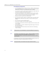
Download Polycom Wireless Server 6000
Transcript
Polycom KIRK Wireless Server 6000 ® ® Installation and Configuration Guide 14168000 Version 2 KIRK Wireless Server 6000 Installation and Configuration Guide Copyright © Polycom, Inc. All Rights Reserved Catalog No. 14168000 Version 1 Proprietary and Confidential The information contained herein is the sole intellectual property of Polycom, Inc. No distribution, reproduction or unauthorized use of these materials is permitted without the expressed written consent of Polycom, Inc. Information contained herein is subject to change without notice and does not represent commitment of any type on the part of Polycom, Inc. Polycom and Accord are registered trademarks of Polycom, Inc. Notice While reasonable effort was made to ensure that the information in this document was complete and accurate at the time of printing, Polycom, Inc., cannot assume responsibility for any errors. Changes and/or corrections to the information contained in this document may be incorporated into future issues. ii Contents Contents Preface Important Information Before You Begin . . . . . . . . . . . . . . . . . . . . . . . . . . 1–1 Chapter Overview . . . . . . . . . . . . . . . . . . . . . . . . . . . . . . . . . . . . . . . . . . . . . . 1–2 Related Documentation . . . . . . . . . . . . . . . . . . . . . . . . . . . . . . . . . . . . . . . . . 1–4 Acronyms . . . . . . . . . . . . . . . . . . . . . . . . . . . . . . . . . . . . . . . . . . . . . . . . . . . . . 1–5 Introduction to KIRK Wireless Server 6000 Components of the KIRK Wireless Server 6000 Solution . . . . . . . . . . . . . 2–2 KIRK Wireless Server 6000 . . . . . . . . . . . . . . . . . . . . . . . . . . . . . . . . . . . 2–2 Wireless Bands . . . . . . . . . . . . . . . . . . . . . . . . . . . . . . . . . . . . . . . . . . . . . 2–3 KIRK Media Resource . . . . . . . . . . . . . . . . . . . . . . . . . . . . . . . . . . . . . . . 2–3 Codec Module . . . . . . . . . . . . . . . . . . . . . . . . . . . . . . . . . . . . . . . . . . . . . . 2–4 KIRK Base Station . . . . . . . . . . . . . . . . . . . . . . . . . . . . . . . . . . . . . . . . . . . 2–4 KIRK Repeater . . . . . . . . . . . . . . . . . . . . . . . . . . . . . . . . . . . . . . . . . . . . . . 2–5 KIRK Handset . . . . . . . . . . . . . . . . . . . . . . . . . . . . . . . . . . . . . . . . . . . . . . 2–6 Auto Login and Handover . . . . . . . . . . . . . . . . . . . . . . . . . . . . . . . . 2–6 KIRK SIO Application Interface . . . . . . . . . . . . . . . . . . . . . . . . . . . . . . . 2–6 KIRK Maintenance Software . . . . . . . . . . . . . . . . . . . . . . . . . . . . . . . . . . 2–7 Administrative Computer . . . . . . . . . . . . . . . . . . . . . . . . . . . . . . . . . . . . 2–7 Requirements for the KIRK Wireless Server 6000 Solution . . . . . . . . . . . . 2–7 KIRK Wireless Server 6000/KIRK Media Resources . . . . . . . . . . . . . 2–7 Environmental Requirements . . . . . . . . . . . . . . . . . . . . . . . . . . . . . 2–7 Electrical Requirements . . . . . . . . . . . . . . . . . . . . . . . . . . . . . . . . . . 2–8 KIRK Base Stations and KIRK Repeaters . . . . . . . . . . . . . . . . . . . . . . . 2–8 Environmental Requirements . . . . . . . . . . . . . . . . . . . . . . . . . . . . . 2–8 Electrical Requirements for Base Station . . . . . . . . . . . . . . . . . . . . 2–9 Electrical Requirements for Repeater . . . . . . . . . . . . . . . . . . . . . . . 2–9 KIRK Handsets . . . . . . . . . . . . . . . . . . . . . . . . . . . . . . . . . . . . . . . . . . . . 2–10 Environmental Requirements . . . . . . . . . . . . . . . . . . . . . . . . . . . . 2–10 Electrical Requirements . . . . . . . . . . . . . . . . . . . . . . . . . . . . . . . . . 2–10 KIRK Maintenance Software . . . . . . . . . . . . . . . . . . . . . . . . . . . . . . . . . 2–10 Software Requirements . . . . . . . . . . . . . . . . . . . . . . . . . . . . . . . . . 2–10 Installation Prerequisites . . . . . . . . . . . . . . . . . . . . . . . . . . . . . . . . . . . . . . . 2–11 11 KIRK Wireless Server 6000 Installation and Configuration Guide Deploying KIRK Wireless Server 6000 Recommendations for KIRK Base Station/KIRK Repeater Placement . . 3–2 Deployment of a KIRK Wireless Server 6000 Multi-Cell . . . . . . . . . . . . . . 3–3 Sync over Air . . . . . . . . . . . . . . . . . . . . . . . . . . . . . . . . . . . . . . . . . . . . . . . 3–3 Examples of Synchronization Chains . . . . . . . . . . . . . . . . . . . . . . . . . . 3–4 Sync Chain With One Sync Master (Primary Sync Ways) . . . . . 3–5 Sync Chain With Alternative Sync Ways . . . . . . . . . . . . . . . . . . . . 3–6 Sync Chain With and Without Alternative Sync Ways . . . . . . . . 3–9 Installing KIRK Wireless Server 6000 and KIRK Media Resource Description of KWS6000/KIRK Media Resource . . . . . . . . . . . . . . . . . . . . 4–2 Types and Part Numbers . . . . . . . . . . . . . . . . . . . . . . . . . . . . . . . . . . . . . 4–2 KWS6000 Types and Part Numbers . . . . . . . . . . . . . . . . . . . . . . . . 4–2 KIRK Media Resource Types and Part Numbers . . . . . . . . . . . . . 4–2 KWS6000/KIRK Media Resource Appearance and Components . . 4–3 KWS6000/KIRK Media Resource LED Indicators . . . . . . . . . . . . . . . . 4–5 Front Cover . . . . . . . . . . . . . . . . . . . . . . . . . . . . . . . . . . . . . . . . . . . . 4–5 Faceplate . . . . . . . . . . . . . . . . . . . . . . . . . . . . . . . . . . . . . . . . . . . . . . . 4–5 KWS6000/KIRK Media Resource - Reset Button . . . . . . . . . . . . . . . . . 4–6 Resetting the KWS6000/KIRK Media Resource Hardware . . . . 4–6 Installing the KWS6000/KIRK Media Resource . . . . . . . . . . . . . . . . . . . . . 4–7 Installing KIRK Codec Module Description of KIRK Codec Module . . . . . . . . . . . . . . . . . . . . . . . . . . . . . . . 5–2 KIRK Codec Module Type and Part Number . . . . . . . . . . . . . . . . . . . 5–2 KIRK Codec Module Appearance . . . . . . . . . . . . . . . . . . . . . . . . . . . . . 5–2 Installing the KIRK Codec Module . . . . . . . . . . . . . . . . . . . . . . . . . . . . . . . . 5–3 Installing KIRK Base Station KIRK Base Station Description . . . . . . . . . . . . . . . . . . . . . . . . . . . . . . . . . . . 6–1 KIRK Base Station provides RF Channels to KIRK Handsets . . . . . . 6–1 KIRK Base Station Types and Part Numbers . . . . . . . . . . . . . . . . . . . . 6–2 KIRK Base Station Appearance and Components . . . . . . . . . . . . . . . . 6–2 KIRK Base Station LED Indicators . . . . . . . . . . . . . . . . . . . . . . . . . . . . . 6–4 Front Cover . . . . . . . . . . . . . . . . . . . . . . . . . . . . . . . . . . . . . . . . . . . . 6–4 Faceplate . . . . . . . . . . . . . . . . . . . . . . . . . . . . . . . . . . . . . . . . . . . . . . . 6–4 KIRK Base Station - Reset Button . . . . . . . . . . . . . . . . . . . . . . . . . . . . . . 6–5 Resetting the KIRK Base Station Hardware . . . . . . . . . . . . . . . . . 6–5 Installing the KIRK Base Station . . . . . . . . . . . . . . . . . . . . . . . . . . . . . . . . . . 6–5 12 Contents Wall Mounted (Vertical) Installation RF Coverage . . . . . . . . . . . . . . . 6–5 Recording the Installation Information . . . . . . . . . . . . . . . . . . . . . . . . . . . . 6–6 Installing KIRK Repeater KIRK Repeater Description . . . . . . . . . . . . . . . . . . . . . . . . . . . . . . . . . . . . . . 6–1 KIRK Repeater provides RF Channels to KIRK Handsets . . . . . . . . . 6–1 KIRK Repeater Types and Part Numbers . . . . . . . . . . . . . . . . . . . . . . . 6–2 KIRK Repeater - Appearance and Components . . . . . . . . . . . . . . . . . 6–3 KIRK Repeater LED Indicators . . . . . . . . . . . . . . . . . . . . . . . . . . . . . . . . 6–4 Installing the KIRK Repeater . . . . . . . . . . . . . . . . . . . . . . . . . . . . . . . . . . . . . 6–4 Environmental requirements . . . . . . . . . . . . . . . . . . . . . . . . . . . . . . 6–5 Recording the Installation Information . . . . . . . . . . . . . . . . . . . . . . . . . . . . 6–7 Checking Indicators . . . . . . . . . . . . . . . . . . . . . . . . . . . . . . . . . . . . . . . . . . . . . 6–7 Powering the KIRK Repeater . . . . . . . . . . . . . . . . . . . . . . . . . . . . . . . . . . . . . 6–7 Power Options . . . . . . . . . . . . . . . . . . . . . . . . . . . . . . . . . . . . . . . . . . . . . 6–7 Programming a KIRK Repeater with the KIRK Programming Kit . . . . . 6–7 Content of the KIRK Programming Kit Repeater . . . . . . . . . . . . . . . . 6–7 Set up of the Hardware for Repeater Programming . . . . . . . . . . . . . . 6–8 Programming the KIRK Repeater with the ServiceTool . . . . . . . . . . . 6–9 Use of KIRK Repeater With External Antenna . . . . . . . . . . . . . . . . . . . . . 6–18 Synchronization Ways . . . . . . . . . . . . . . . . . . . . . . . . . . . . . . . . . . . . . . 6–18 Preparing KIRK Handset for Use KIRK Handset Description . . . . . . . . . . . . . . . . . . . . . . . . . . . . . . . . . . . . . . . 8–1 KIRK Handset Types and Part Numbers . . . . . . . . . . . . . . . . . . . . . . . 8–2 KIRK Charger Types and Part Numbers . . . . . . . . . . . . . . . . . . . . . . . 8–2 Power Supply Types and Part Numbers . . . . . . . . . . . . . . . . . . . . . . . 8–3 Installing Battery . . . . . . . . . . . . . . . . . . . . . . . . . . . . . . . . . . . . . . . . . . . . . . . 8–4 Installing Battery on KIRK 3040 Handsets . . . . . . . . . . . . . . . . . . . . . . 8–5 Installing Battery on KIRK 4020/KIRK 4040/KIRK 4080 Handsets . 8–5 Installing Battery on KIRK 5020 and KIRK 5040 Handsets . . . . . . . . 8–6 Charging KIRK Handsets . . . . . . . . . . . . . . . . . . . . . . . . . . . . . . . . . . . . . . . . 8–7 Using the Charger . . . . . . . . . . . . . . . . . . . . . . . . . . . . . . . . . . . . . . . . . . . 8–7 Charging Battery . . . . . . . . . . . . . . . . . . . . . . . . . . . . . . . . . . . . . . . . . . . . 8–9 KIRK 3040/KIRK 4020/KIRK 4040 and KIRK 4080 Handsets . . 8–9 KIRK 5020/5040 Handsets . . . . . . . . . . . . . . . . . . . . . . . . . . . . . . . 8–10 Retrieving the Serial Number of the KIRK Handset . . . . . . . . . . . . . . . . 8–12 Retrieving Serial Number on KIRK 3040 Handsets . . . . . . . . . . . . . . 8–12 Retrieving Serial Number on KIRK 4020/KIRK 4040/KIRK 4080 Handsets . . . . . . . . . . . . . . . . . . . . . . . . . . . . . . . . . . . . . . . . . . . . . . . . . 8–13 13 KIRK Wireless Server 6000 Installation and Configuration Guide Retrieving Serial Number on KIRK 5020/5040 Handsets . . . . . . . . 8–14 Basic Network Configuration Recommended Network Configuration . . . . . . . . . . . . . . . . . . . . . . . . . . . . 9–1 Assigning DHCP Server Options . . . . . . . . . . . . . . . . . . . . . . . . . . . . . . . . . 9–2 Assigning DHCP Server Reservations . . . . . . . . . . . . . . . . . . . . . . . . . . . . . 9–2 Configuring KIRK Wireless Server 6000 Powering up the KWS6000 . . . . . . . . . . . . . . . . . . . . . . . . . . . . . . . . . . . . . . 10–1 Local Power Supply . . . . . . . . . . . . . . . . . . . . . . . . . . . . . . . . . . . . . . . . 10–1 Connecting a Computer to the KWS6000 . . . . . . . . . . . . . . . . . . . . . . . . . . 10–2 Accessing the Web Based Administration Page . . . . . . . . . . . . . . . . . . . . 10–3 How to Change Internet Protocol Properties using Windows XP . 10–3 How to Access the Administration Page . . . . . . . . . . . . . . . . . . . . . . 10–5 Entering a System User Name and Password . . . . . . . . . . . . . . . 10–6 Configuring a KIRK Wireless Server 6000 Using Static IP Address . . . 10–7 General Configuration . . . . . . . . . . . . . . . . . . . . . . . . . . . . . . . . . . . . . . 10–8 Wireless Server Configuration . . . . . . . . . . . . . . . . . . . . . . . . . . . . . . . 10–9 Built-In Media Resource Configuration . . . . . . . . . . . . . . . . . . . . . . 10–10 SIP Configuration . . . . . . . . . . . . . . . . . . . . . . . . . . . . . . . . . . . . . . . . . 10–11 Security Configuration . . . . . . . . . . . . . . . . . . . . . . . . . . . . . . . . . . . . . 10–14 Configuring a KIRK Wireless Server 6000 Using DHCP . . . . . . . . . . . . 10–15 General Configuration . . . . . . . . . . . . . . . . . . . . . . . . . . . . . . . . . . . . . 10–15 Wireless Server Configuration . . . . . . . . . . . . . . . . . . . . . . . . . . . . . . 10–16 Built-In Media Resource Configuration . . . . . . . . . . . . . . . . . . . . . . 10–17 SIP Configuration . . . . . . . . . . . . . . . . . . . . . . . . . . . . . . . . . . . . . . . . . 10–17 Security Configuration . . . . . . . . . . . . . . . . . . . . . . . . . . . . . . . . . . . . . 10–17 Checking Indicators . . . . . . . . . . . . . . . . . . . . . . . . . . . . . . . . . . . . . . . . . . . 10–17 Making a Back-Up of the Configuration File . . . . . . . . . . . . . . . . . . . . . . 10–17 Configuring KIRK Media Resources Powering up the KIRK Media Resource . . . . . . . . . . . . . . . . . . . . . . . . . . 11–1 Local Power Supply . . . . . . . . . . . . . . . . . . . . . . . . . . . . . . . . . . . . . . . . 11–2 Connecting a Computer to the KIRK Media Resource . . . . . . . . . . . . . . 11–2 Accessing the Web Based Administration Page . . . . . . . . . . . . . . . . . . . . 11–3 How to Change Internet Protocol Properties using Windows XP . 11–3 How to Access the Administration Page . . . . . . . . . . . . . . . . . . . . . . 11–5 Entering a System User Name and Password . . . . . . . . . . . . . . . 11–5 Configuring a KIRK Media Resource Using DHCP . . . . . . . . . . . . . . . . . 11–6 14 Contents Configuring a KIRK Media Resource Using Static IP Address . . . . . . . 11–7 General Configuration . . . . . . . . . . . . . . . . . . . . . . . . . . . . . . . . . . . . . . 11–7 Media Resource Configuration . . . . . . . . . . . . . . . . . . . . . . . . . . . . . . . 11–7 Checking Indicators . . . . . . . . . . . . . . . . . . . . . . . . . . . . . . . . . . . . . . . . . . . . 11–7 Making a Back-Up of the Configuration File . . . . . . . . . . . . . . . . . . . . . . . 11–8 Configuring KIRK Base Station Powering up the KIRK Base Station . . . . . . . . . . . . . . . . . . . . . . . . . . . . . . 12–1 Connecting a Computer to the KIRK Base Station . . . . . . . . . . . . . . . . . . 12–2 Accessing the Web Based Administration Page . . . . . . . . . . . . . . . . . . . . 12–3 How to Change Internet Protocol Properties using Windows XP . 12–3 How to Access the Administration Page . . . . . . . . . . . . . . . . . . . . . . 12–5 Entering a System User Name and Password . . . . . . . . . . . . . . . 12–5 Configuring a KIRK Base Station Using DHCP . . . . . . . . . . . . . . . . . . . . 12–6 General Configuration . . . . . . . . . . . . . . . . . . . . . . . . . . . . . . . . . . . . . . 12–7 Security Configuration . . . . . . . . . . . . . . . . . . . . . . . . . . . . . . . . . . . . . . 12–7 Sync. Ways Configuration . . . . . . . . . . . . . . . . . . . . . . . . . . . . . . . . . . . 12–8 Configuring a KIRK Base Station Using Static IP Address . . . . . . . . . . . 12–9 General Configuration . . . . . . . . . . . . . . . . . . . . . . . . . . . . . . . . . . . . . 12–10 Base Station Configuration . . . . . . . . . . . . . . . . . . . . . . . . . . . . . . . . . 12–11 Security Configuration . . . . . . . . . . . . . . . . . . . . . . . . . . . . . . . . . . . . . 12–11 Sync. Ways Configuration . . . . . . . . . . . . . . . . . . . . . . . . . . . . . . . . . . 12–11 Checking Indicators . . . . . . . . . . . . . . . . . . . . . . . . . . . . . . . . . . . . . . . . . . . 12–11 Making a Back-Up of the Configuration File . . . . . . . . . . . . . . . . . . . . . . 12–11 KIRK Handset Registration and Subscription Registering KIRK Handsets . . . . . . . . . . . . . . . . . . . . . . . . . . . . . . . . . . . . . 13–1 Subscribing KIRK Handsets . . . . . . . . . . . . . . . . . . . . . . . . . . . . . . . . . . . . . 13–3 KIRK 3040 Handset . . . . . . . . . . . . . . . . . . . . . . . . . . . . . . . . . . . . . . . . 13–3 Subscribing Handsets . . . . . . . . . . . . . . . . . . . . . . . . . . . . . . . . . . . 13–5 Subscribing a Handset to Different Systems . . . . . . . . . . . . . . . . 13–5 KIRK 4020/4040/4080 Handset . . . . . . . . . . . . . . . . . . . . . . . . . . . . . . 13–6 Subscribing Handsets . . . . . . . . . . . . . . . . . . . . . . . . . . . . . . . . . . . 13–8 Subscribing a Handset to Different Systems . . . . . . . . . . . . . . . . 13–8 KIRK 5020/5040 Handset . . . . . . . . . . . . . . . . . . . . . . . . . . . . . . . . . . . 13–9 Creating Login (Subscribing Handset) . . . . . . . . . . . . . . . . . . . . 13–10 Subscribing a Handset to Different Systems . . . . . . . . . . . . . . . 13–11 KIRK Handset Management Viewing Handset/User Configuration . . . . . . . . . . . . . . . . . . . . . . . . . . . 14–2 15 KIRK Wireless Server 6000 Installation and Configuration Guide Searching for Handset/User Information . . . . . . . . . . . . . . . . . . . . . . . . . 14–2 Unsubscribing KIRK Handsets . . . . . . . . . . . . . . . . . . . . . . . . . . . . . . . . . . 14–3 KIRK 3040/4020/4040/4080 Handset . . . . . . . . . . . . . . . . . . . . . . . . . 14–3 KIRK 5020/5040 Handset . . . . . . . . . . . . . . . . . . . . . . . . . . . . . . . . . . . 14–4 Removing KIRK Handsets from the List (Deregistering) . . . . . . . . . . . . 14–4 Changing User Configurations . . . . . . . . . . . . . . . . . . . . . . . . . . . . . . . . . . 14–6 Exporting Handset Registration Data . . . . . . . . . . . . . . . . . . . . . . . . . . . . . 14–7 Restoring Handset Registration Data . . . . . . . . . . . . . . . . . . . . . . . . . . . . . 14–9 Importing Handset Registration Data - CSV Format . . . . . . . . . . . . . . . 14–11 Adjusting the KIRK Handset . . . . . . . . . . . . . . . . . . . . . . . . . . . . . . . . . . . 14–13 Content of the KIRK Programming Kit Handset . . . . . . . . . . . . . . . 14–13 Set up of the Hardware for KIRK Handset Adjustment . . . . . . . . . 14–14 Adjusting the KIRK Handset with the ServiceTool . . . . . . . . . . . . . 14–14 System Management KIRK Wireless Server 6000 . . . . . . . . . . . . . . . . . . . . . . . . . . . . . . . . . . . . . . 15–2 Changing System User Name and Password . . . . . . . . . . . . . . . . . . . 15–2 Reading System Information . . . . . . . . . . . . . . . . . . . . . . . . . . . . . . . . 15–3 General Status Information . . . . . . . . . . . . . . . . . . . . . . . . . . . . . . 15–3 Logs Information . . . . . . . . . . . . . . . . . . . . . . . . . . . . . . . . . . . . . . . 15–4 Wireless Server Information . . . . . . . . . . . . . . . . . . . . . . . . . . . . . 15–5 Packet Capture Information . . . . . . . . . . . . . . . . . . . . . . . . . . . . . 15–6 Reading Statistics . . . . . . . . . . . . . . . . . . . . . . . . . . . . . . . . . . . . . . . . . . 15–7 Wireless Server . . . . . . . . . . . . . . . . . . . . . . . . . . . . . . . . . . . . . . . . 15–7 Media Resource . . . . . . . . . . . . . . . . . . . . . . . . . . . . . . . . . . . . . . . . 15–8 Base Station . . . . . . . . . . . . . . . . . . . . . . . . . . . . . . . . . . . . . . . . . . . 15–9 Active Calls . . . . . . . . . . . . . . . . . . . . . . . . . . . . . . . . . . . . . . . . . . . 15–9 Abnormal Releases . . . . . . . . . . . . . . . . . . . . . . . . . . . . . . . . . . . . . 15–9 Traffic Distribution . . . . . . . . . . . . . . . . . . . . . . . . . . . . . . . . . . . . 15–10 Provisioning Configuration . . . . . . . . . . . . . . . . . . . . . . . . . . . . . .15–11 Clusters . . . . . . . . . . . . . . . . . . . . . . . . . . . . . . . . . . . . . . . . . . . . . . .15–11 Phonebook configuration . . . . . . . . . . . . . . . . . . . . . . . . . . . . . . .15–12 Making a Back-Up of the Configuration File . . . . . . . . . . . . . . . . . . 15–13 Restoring Configuration File . . . . . . . . . . . . . . . . . . . . . . . . . . . . . . . 15–15 Updating the KIRK Wireless Server 6000 . . . . . . . . . . . . . . . . . . . . . 15–16 Updating KIRK Wireless Server 6000 Firmware . . . . . . . . . . . 15–16 Restarting the KIRK Wireless Server 6000 . . . . . . . . . . . . . . . . . . . . 15–17 KIRK Media Resource . . . . . . . . . . . . . . . . . . . . . . . . . . . . . . . . . . . . . . . . . 15–20 16 Contents Changing System User Name and Password . . . . . . . . . . . . . . . . . . 15–20 Reading System Information . . . . . . . . . . . . . . . . . . . . . . . . . . . . . . . 15–21 General Status Information . . . . . . . . . . . . . . . . . . . . . . . . . . . . . 15–21 Logs Information . . . . . . . . . . . . . . . . . . . . . . . . . . . . . . . . . . . . . . 15–22 Reading Statistics . . . . . . . . . . . . . . . . . . . . . . . . . . . . . . . . . . . . . . . . . 15–24 Updating the KIRK Media Resource Firmware . . . . . . . . . . . . . . . . 15–24 Updating KIRK Media Resource Firmware . . . . . . . . . . . . . . . 15–24 KIRK Base Station . . . . . . . . . . . . . . . . . . . . . . . . . . . . . . . . . . . . . . . . . . . . 15–26 Changing System User Name and Password . . . . . . . . . . . . . . . . . . 15–26 Reading System Information . . . . . . . . . . . . . . . . . . . . . . . . . . . . . . . 15–27 General Status Information . . . . . . . . . . . . . . . . . . . . . . . . . . . . . 15–27 Logs Information . . . . . . . . . . . . . . . . . . . . . . . . . . . . . . . . . . . . . . 15–28 Reading Statistics . . . . . . . . . . . . . . . . . . . . . . . . . . . . . . . . . . . . . . . . . 15–29 Sync State of Base Station . . . . . . . . . . . . . . . . . . . . . . . . . . . . . . . . . . 15–29 Checking Sync State . . . . . . . . . . . . . . . . . . . . . . . . . . . . . . . . . . . 15–30 Updating the KIRK Base Station Firmware . . . . . . . . . . . . . . . . . . . 15–31 Updating KIRK Base Station Firmware . . . . . . . . . . . . . . . . . . . 15–31 Messaging over MSF Description of Different Types of MSF Messages . . . . . . . . . . . . . . . . . . . 16–1 Sending Text Messages . . . . . . . . . . . . . . . . . . . . . . . . . . . . . . . . . . . . . . . . . 16–3 Regulatory Notices International Regulatory and Product Information . . . . . . . . . . . . . . . . . 17–1 Important Safety Instructions and Product Information . . . . . . . . . . . . . 17–7 Open Source Software Notice Open Source Software Notice . . . . . . . . . . . . . . . . . . . . . . . . . . . . . . . . . . . 18–1 17 1 Preface This guide is intended for qualified technicians who will install, configure and maintain the KIRK Wireless Server 6000 (KWS6000) Solution. To qualify to install the KWS6000 Solution, you must have successfully completed the KWS6000 technical training. The guide provides all the necessary information for successful installation and maintenance of the wireless solutions. This includes the installation and configuration of: • KIRK Wireless Server 6000 • KIRK Media Resource • KIRK Codec Module • KIRK Base Station • KIRK Repeater • KIRK Handset The Installation Guide also provides you with information about: • Web based Administration Page of the KWS6000, media resource and base station Important Information Before You Begin This guide assumes the following: Note • that users have a working knowledge of the call handlers operations • that the call handler is installed and initialized and is working correctly • that you have a working knowledge of deployment in general • that a site survey has been conducted and that the installer has access to these plans The site survey should determine the number of handsets and how many RF channels are needed. 1–1 KIRK Wireless Server 6000 Installation and Configuration Guide Chapter Overview 1–2 Where is it? What is it about? When to use it? Chapter 2 Introduction to KIRK Wireless Server 6000 To learn about the different components in a typical KWS6000 configuration. Chapter 3 Deploying the KIRK Wireless Server 6000 To learn how to deploy a KWS6000 Multi-cell installation. Chapter 4 Installing KIRK Wireless Server 6000 and KIRK Media Resource To learn about KWS6000/KIRK Media Resource and to install it. Chapter 5 Installing KIRK Codec Module To learn about the KIRK Codec Module and to install it in a KIRK Media Resource. Chapter 6 Installing KIRK Base Station To learn about the KIRK Base Station and to mount it onto wall indoors. Chapter 7 Installing KIRK Repeater To learn about the KIRK Repeater and to mount repeater onto wall or ceiling indoors. Chapter 8 Preparing KIRK Handset for Use To prepare KIRK Handsets for use, installing and charging battery. Chapter 9 Basic Network Configuration To learn about DHCP and TCP/IP Setup and to assign options to DHCP server. Chapter 10 Configuring KIRK Wireless Server 6000 To power up the KWS6000, connect a computer to the KWS6000, access the web based Administration Page and configure the KWS6000 using DHCP or TCP/IP Setup. Chapter 11 Configuring KIRK Media Resource To power up the KIRK Media Resource, connect a computer to the KIRK Media Resource, access the web based Administration Page and configure the KIRK Media Resource using DHCP or TCP/IP Setup. Preface Where is it? What is it about? When to use it? Chapter 12 Configuring KIRK Base Station To power up the KIRK Base Station, connect a computer to the KIRK Base Station, access the web based Administration Page and configure the KIRK Base Station using DHCP or TCP/IP Setup. Chapter 13 KIRK Handset Registration and Subscription To register and subscribe KIRK Handsets. Chapter 14 KIRK Handset Management To unsubscribe and deregister KIRK Handsets. To change user configuration and adjust handsets. Chapter 15 System Management To define and view different settings of the system, reading statistics, making a backup of configuration file, updating system software, and resetting the system. Chapter 16 Messaging over MSF To enable the MSF messages function. Chapter 17 Regulatory Notices To learn about safety regulation for the KWS6000. Chapter 18 Open Source Software Notice To provide information about the Open Source Software. 1–3 KIRK Wireless Server 6000 Installation and Configuration Guide Related Documentation For further information about the KWS6000 not covered by this manual, refer to the following documentation: Subject Documentation Deployment Kit Deployment Guide Handset Operation Handset User’s Guide Release Notes Every software release is accompanied by a release note. The release note describes software changes, bug fixes, outstanding issues, and hardware compability considerations for the new software release. Read the release note before you begin a software upgrade! To obtain the release note, see www.polycom.com 1–4 Preface Acronyms AC Authentication Code ARI no. Access Rights Identity - Serial number of the KWS6000 dB Decibels (deciBells) DECT Digital Enhanced Cordless Telecommunications DHCP Dynamic Host Configuration Protocol DNS Domain Name System e.i.r.p. Equivalent Isotropic Radiated Power GAP Generic Access Profile HW PCS Hardware Product Change Status - Hardware edition IP Internet Protocol IPEI International Portable Equipment Identity - Serial number of the handset - SN KWS KIRK Wireless Server LAN Local Area Network LED Light Emitting Diode MAC Media Access Control - hardware address of a device connected to a network MTU Maximum Transmission Unit MWI Message Waiting Indication NIC Network Interface Card NTP Network Time Protocol PBX Private Branch eXchange PCS Product Change Status (Edition) PoE Power over Ethernet PP Portable Parts - wireless handset RSSI Received Signal Strength Indicator RTP Real-time Transport Protocol SIP Session Initiated Protocol SW PCS Software Product Change Status - Software edition TFTP Trivial File Transfer Protocol UDP User Datagram Protocol 1–5 KIRK Wireless Server 6000 Installation and Configuration Guide 1–6 VoIP Voice over Internet Protocol WLAN Wireless Local Area Network WRFP Wireless Radio Fixed Part - Wireless Repeater 2 Introduction to KIRK Wireless Server 6000 This section provides a description of the KWS6000 solution. A typical KWS6000 configuration includes a number of the following components, in addition to the KWS6000: • Media resources • Base stations • Repeaters • Handsets and accessories Figure 2-1 Overview of the Whole Solution 2–1 KIRK Wireless Server 6000 Installation and Configuration Guide This section provides information about: • “Components of the KIRK Wireless Server 6000 Solution” on page 2-2 • “Requirements for the KIRK Wireless Server 6000 Solution” on page 2-7 • “Installation Prerequisites” on page 2-11 Components of the KIRK Wireless Server 6000 Solution This section provides information about: • “KIRK Wireless Server 6000” on page 2-2 • “Wireless Bands” on page 2-3 • “KIRK Media Resource” on page 2-3 • “KIRK Base Station” on page 2-4 • “KIRK Repeater” on page 2-5 • “KIRK Handset” on page 2-6 • “KIRK Maintenance Software” on page 2-7 • “Administrative Computer” on page 2-7 KIRK Wireless Server 6000 Below you will find an overview of the system capacity of the KWS6000. Table 2-1 Overview of System Capacity Description Capacity Max. number of base stations. 256 Note: A minimum of 1 base station is required, as the KWS6000 does not have a built-in radio. 2–2 Max. number of simultaneous calls on each base station 11 Max. number of repeaters on each base station 3 Max. number of simultaneous calls on a KWS6000/media resource (G.711) 32 Max. number of media resources 32 Max. number of simultaneous calls with 32 media resources 1024 Introduction to KIRK Wireless Server 6000 Table 2-1 Overview of System Capacity Description Capacity Max. number of simultaneous calls on each KWS6000/media resource with Codec Module 24 Max. number of simultaneous calls with 32 media resources with Codec Module. 768 Note: If the Codec Module is used, it is recommended to install it in al media resources. Max. number of registered handsets 4096 The KWS6000 controls the wireless infrastructure. It manages media resources, base stations, repeaters and the IP interface to the call handler. The communication protocol between the KWS6000 and the call handler is SIP A KWS6000 is installed directly on the LAN and must be managed as part of the corporate network. For more information about the KWS6000, refer to “Deploying KIRK Wireless Server 6000” on page 3-1, “Installing KIRK Wireless Server 6000 and KIRK Media Resource” on page 4-1 and “Configuring KIRK Wireless Server 6000” on page 10-1. Wireless Bands The wireless solution supports two wireless bands, allowing operation in various countries and regions. Supported wireless bands are: • ETSI DECT (1880-1900 Mhz), referred to as DECT • USA DECT (1920-1930 Mhz), referred to as 1G9 The wireless band used by a KWS6000 solution is determined by the base stations and handsets ordered with the solution. KIRK Media Resource The media resource performs media conversion between the call handler and the KWS6000 and is the media termination point for incoming and outgoing calls. A maximum of 32 media resources can be added to a KWS6000. Each media resource adds 32 voice channels to the system. Adding 32 media resources makes it possible to have 1024 calls at the same time. Note The KWS6000 contains one media resource. 2–3 KIRK Wireless Server 6000 Installation and Configuration Guide Codec Module It is possible to install a Codec Module in the media resource. The Codec Module adds a number of codecs, allowing the wireless server to interface to G.729A. Note When installing a Codec Module, the media resource only adds 24 voice channels to the system. Adding 32 media resources with codec modules makes it possible to have 768 calls at the same time. For more information about media resources, refer to “Installing KIRK Wireless Server 6000 and KIRK Media Resource” on page 4-1 and “Configuring KIRK Media Resources” on page 11-1. For more information about installing the Codec Module, refer to “Installing KIRK Codec Module” on page 5-1. KIRK Base Station The base stations are positioned in the area to send and receive calls between the wireless server and the handset. The base station contains internal antennas and handles 11 speech channels simultaneously. A base station is able to synchronize with other base stations. When the base station is synchronized with other base stations, a person speaking in a handset can move between base stations without any interference. Transmission length is up to 100 meters/329 feet according to IEEE 802.3u on a twisted pair cable, e.g. cat.5e. The base station is a class 1 PoE device (802.3af) and must be powered accordingly (maximum power supply consumption 3.0W according to PoE 802.3af). The radius coverage of the base station is up to 90 meters/295 feet indoor and up to 300 meters/984 feet outdoor, with a handset in line-of-sight. Coverage area decreases depending on choice of building materials and obstructive elements. To ensure proper coverage in the areas required, it is necessary to conduct a site survey and deployment by certified technicians. For more information about deployment, refer to the Deployment Guide accompanying the Deployment Kit. For more information about the base station, refer to “Installing KIRK Base Station” on page 6-1 and “Configuring KIRK Base Station” on page 12-1. 2–4 Introduction to KIRK Wireless Server 6000 KIRK Repeater The repeater can be used to extend the coverage area in a wireless solution. Depending on the repeater type, it can be mounted either on the wall or on the ceiling. The wireless repeater is used in areas with limited voice traffic, where cabling is difficult. The repeater does not increase the number of traffic channels, but increases the coverage area established with the base station. Up to three repeaters can be placed in cascade formation directing coverage in a certain direction. The base station can support up to 3 repeaters. For more information about the repeater, refer to “Installing KIRK Repeater” on page 6-1. 2–5 KIRK Wireless Server 6000 Installation and Configuration Guide KIRK Handset The handset is a lightweight, ergonomically designed wireless unit that includes an LCD display and keypad. The handset is a portable unit compatible with DECT GAP standard. The handset is designed to provide the subscriber with most of the features available for a wired phone, in addition to its roaming and handover capabilities. The KWS6000 supports up to 4096 registered handsets. For more information about the handset, refer to “Preparing KIRK Handset for Use” on page 8-1, “KIRK Handset Registration and Subscription” on page 13-1 and “KIRK Handset Management” on page 14-1. Auto Login and Handover Auto login refers to the ability to log on to more than one system, enabling you to use the same handset on up to 10 different systems. If a handset is subscribed to two or more systems, you can use Auto Login type A or Auto Login type B to change between the systems automatically: Note • Auto Login type A is used if a handset is subscribed to two or more systems. Auto Login A should only be used in separate systems without overlaps. • Auto Login type B is used if a handset is subscribed to two systems only. Auto Login B can be used in separate systems which are overlapping each other. Auto Login type B is only supported in 4020/4040/4080 Handsets. For more information about Auto Login, refer to “Subscribing KIRK Handsets” on page 13-3. Handover refers to the ability to move between the coverage areas of different radio units on the same system while talking, without interruptions in the conversation. KIRK SIO Application Interface The SIO Application Interface is a communication platform allowing text messaging between the wireless server and a handset. With the SIO API, which is a fundamental part of all our solutions, and a third party application program, the customer is offered a wide range of usage opportunities in a variety of vertical markets. 2–6 Introduction to KIRK Wireless Server 6000 KIRK Maintenance Software The following software application for the installation and maintenance of the KWS6000 Solution is provided: • ServiceTool Used for programming of the repeater, adjustment of the handset and software download to repeater/handset. Note ServiceTool is not used for adjustment of the 5020 Handset. The ServiceTool application can be downloaded from www.polycom.com. Administrative Computer An administrative computer is required for configuration and maintenance of the KWS6000, media resource and base station. This computer may be temporarily connected directly to the device or to the network. A dedicated computer is not required. Requirements for the KIRK Wireless Server 6000 Solution This section provides information about the environmental and electrical requirements and software requirements for the KWS6000 solution. KIRK Wireless Server 6000/KIRK Media Resources Environmental Requirements The installation area must: Note • be clean, free of traffic and excess dust, dry, and well ventilated • be within the temperature ranges of 10°C and 40°C/50°F and 104°F • be between 20% and 80% non-condensing relative humidity The installation area must be of sufficient height from the floor to prevent water damage. 2–7 KIRK Wireless Server 6000 Installation and Configuration Guide Electrical Requirements The following electrical requirements must be met: • Power consumption: 8V/500 mA • Typical power consumption: 5W per unit • The supplied power for the AC adaptor power supply must be 110 to 240 ac nominal, 50/60 Hz. KIRK Base Stations and KIRK Repeaters Environmental Requirements 2–8 • Avoid installing base stations and repeaters on large concrete or marble columns because these columns affect radio coverage. If possible, place the base station a minimum of one meter/3.3 feet from these types of columns. • Do not install a base station or repeater with the antenna housings near metal objects. Be careful not to damage existing wiring or panels. • Do not position base stations and repeaters in ducts, plenums, or hollow spaces used to transport environmental air except where the duct, plenum or hollow space is created by a suspended ceiling having lay-in panels. When you need more than one base station in a cell to meet traffic requirements, position the base stations at the same cell center. • Keep the base station and repeater away from steel constructions. • Do not position base stations and repeaters directly on metallic surfaces. If possible, place the base station a minimum of one meter/3.3 feet from these types of surfaces. • Do not position base station and repeaters behind furniture. • Only position base stations and repeaters where the signal is needed. • The installation area must be clean, free of traffic and excess dust, dry, and well ventilated. • The installation area must be within the temperature ranges of 10°C and 40°C/50°F and 104°F. • The installation area must be between 20% and 80% non-condensing relative humidity. Introduction to KIRK Wireless Server 6000 • Minimum distance between two base stations varies depending on material and construction of buildings, but there must always be synchronization chains and radio coverage overlap between the two base stations or handover between radio units. The time it takes a person to cross the common coverage area must be 10 seconds or more, as the handset needs time to scan for an alternative base station. Electrical Requirements for Base Station The following electrical requirements must be met: • The base station operates on standard twisted pair ethernet cable - e.g. minimum Cat.5e - to prevent disturbances from other equipment. • Maximum power supply consumption is 3.0W (IEEE 802.3af class 1 device). • The max. radiated output power for the antenna is 10mW e.i.r.p/channel. Electrical Requirements for Repeater • The supplied power (power supply) for the charger must be 110 V to 120 V ac nominal (or 220 V to 230 V ac nominal), 50/60 Hz. 2–9 KIRK Wireless Server 6000 Installation and Configuration Guide KIRK Handsets Environmental Requirements • The area where the handset is used must be within the temperature ranges of 0°C and 40°C/32°F and 104°F. • For correct battery charging, the room temperature must be between 0°C and 25°C/32°F and 77°F. Therefore, the handset must not be placed in direct sunlight. The battery has a built-in heat sensor which will stop charging if the battery temperature is too high. • For battery information, refer to “Installing Battery” on page 8-4. • The area where the handset is used must be between 20% and 80% non-condensing relative humidity. Electrical Requirements The following electrical requirement must be met: • The supplied power (power supply) for the charger must be 110 V to 120 V ac nominal (or 220 V to 230 V ac nominal), 50/60 Hz. KIRK Maintenance Software This section describes the computer requirements to run the installation and maintenance tools of the handset and repeater. Software Requirements Note 2– 10 • OS: Windows 2000 (SP4), Windows XP (SP2), Windows Vista • CPU: Minimum 400MHz (2000/XP), 1GHz (Vista) • RAM: Minimum 256 MB (2000/XP), 1 GB (Vista) • GPU/Display: XGA (1024x768) • Harddisk: Minimum recommended harddisk size by OS and other installed applications + 25 MB free space for the application. Depending on other applications running on the system, CPU, RAM and harddisk may vary. Introduction to KIRK Wireless Server 6000 Installation Prerequisites Note Ensure that a site survey and deployment have been conducted and that the installer has access to these plans before proceeding any further. For more information about deployment, refer to “Deploying KIRK Wireless Server 6000” on page 3-1. Before you start the installation you need to find the following information and perform the following tasks: • ARI codes (serial numbers) for the KWS6000 (see label on the rear of the KWS unit) • Serial numbers for handsets. Refer to “Retrieving the Serial Number of the KIRK Handset” on page 8-12. • AC codes (authentication codes) The AC is a customer-defined optional subscription pin code of a maximum of eight digits for the individual handset. The AC can be used when connecting the handset to the KWS. • Repeaters: Mark each repeater with the number of the related base station. This way you can easily configure the system on site. • Handsets: To use the handsets, you must first install the radio infrastructure, e.g. base stations and repeaters to transmit and receive radio signals to and from the handsets. There are no direct connections between the handset and the system. For more information about base station and repeater installation, refer to “Installing KIRK Base Station” on page 6-1 and “Installing KIRK Repeater” on page 6-1. • Charging battery When charging the handset battery for the first time, leave the handset in the charger for 14 - 16 hours to ensure that the battery is fully charged and the handset ready for use. Refer to “Charging KIRK Handsets” on page 8-7. 2–11 KIRK Wireless Server 6000 Installation and Configuration Guide 2–12 3 Deploying KIRK Wireless Server 6000 Before you install the KWS6000 solution, it is necessary to perform a complete site survey and determine the exact location of KWS6000, base stations, repeaters and number of handsets required. A well planned installation should start with an RF coverage site survey. A site survey is designed to determine the optimal location for base stations and repeaters and the amount of wireless voice traffic to be supported by the installation (i.e., how many handsets must maintain voice conversations at the same time, in any given area). Due to the unexpected nature of RF propagation in an indoor environment, an actual on-site test must be performed before the installation is complete. While an extensive guide to effective RF coverage planning is outside the scope of this manual, the following points should be taken into consideration when planning the site, prior to base station and repeater installation: • The base station/repeater provides typical RF coverage of up to 50 meters/164 feet in a typical indoor office environment and up 300 meters/984 feet in an open area (line-of-sight), extending in all directions from the base station/repeater. The exact coverage range depends on the building architecture, wall material and surroundings. • The wireless solution can support a maximum of 4096 handsets. • The wireless solution supports a maximum of 256 base stations. • Handset handover: handsets can move between coverage areas of base stations and repeaters while receiving continuous service and maintaining conversations in progress. • For efficient handover of conversations between base stations, deploy base stations with wide overlap between them (i.e., plan for some areas to be covered by more than one base station). Overlaps are necessary to maintain seamless handover and to establish synchronization chains. A good example may be a cafeteria during lunch hour where temporary 3–1 KIRK Wireless Server 6000 Installation and Configuration Guide concentrations of handsets may occur. The overlap carries the excess call load to adjacent base station to provide uninterrupted services to subscribers. • Typically, installations such as office buildings, hotels and hospitals should be equipped with base stations/repeaters on several floors to create uniform and complete RF coverage. • Open areas can be covered with a sparse network of base stations. In such applications, the base stations/repeaters cover an extended range due to the extended line-of-sight RF propagation capability. • Ensure that there is not a residential DECT system (home DECT) on the site. This section provides information about: • “Recommendations for KIRK Base Station/KIRK Repeater Placement” on page 3-2 • “Deployment of a KIRK Wireless Server 6000 Multi-Cell” on page 3-3 Recommendations for KIRK Base Station/KIRK Repeater Placement 3–2 • In large halls, the base station/repeater (wall) should be installed vertically in the middle of the space below the drop ceiling. • In corridors, the base station/repeater (wall) should be installed vertically preferably at corridor intersections where propagation patterns follow the corridor patterns. The base station/repeater should point towards the corridor and preferably in the middle height between the floor and the actual ceiling. In case there are high objects in the area, the base station/repeater (wall) should be installed above those objects but still kept distant from the ceiling. • The repeater (ceiling) should be installed in the middle of corridors and small rooms. • In multi-story buildings, base stations/repeaters may be installed on opposite sides of the floors to take advantage of the floor-to-floor coverage. The coverage design cannot rely entirely on floor-to-floor propagation; each case must be verified due to variations in local attenuation patterns. • If the building contains a central open space area with windows to the other areas, base stations/repeaters may be installed in this open space to provide a good coverage for the rooms in the inner circle on all floors (e.g. hotels). Deploying KIRK Wireless Server 6000 • If a base station/repeater (wall) hangs vertically on a wall, the RF coverage in front of the base stations/repeaters is twice as large as the coverage at the rear. When a base station/repeater is installed on the outside of an outer wall, the RF coverage behind it is strongly attenuated by the wall. • Base stations/repeaters should not be installed near large metallic objects. • Reinforced concrete structures have a high attenuation factor inside the building. They decrease the RF coverage range of the base stations/repeaters and therefore requires a higher number of base stations/repeaters in the building. Lighter types of construction require fewer base stations since attenuation figures are considerably lower. Deployment of a KIRK Wireless Server 6000 Multi-Cell Note This section only contains deployment information specific to the KWS6000. For more information about deployment in general, refer to the Deployment Guide accompanying the Deployment Kit. The Deployment Guide provides instructions on how to use the Deployment Kit to determine the most suitable locations for the different radio units. Sync over Air As a user moves from one base station radio coverage area to another, the call must be handed over to the next radio unit. To create handover between radio units it is necessary to establish synchronization chains. For more information about synchronization chains, refer to “Examples of Synchronization Chains” on page 3-4. If the synchronization between radio units is lost, then handover is not possible and ongoing calls will be terminated. Note Each base station must be placed within the radio coverage area of at least one other base station or repeater (radio units). 3–3 KIRK Wireless Server 6000 Installation and Configuration Guide Examples of Synchronization Chains Certain rules must be taken into consideration when establishing synchronazation chains: • The distance over which synchronization can take place is limited to a distance similar to a loss of max. 25 dB. If the loss of signal is higher than 25 dB, there is no guarantee that synchronization is stable. Note It is recommended that a base station synchronizes with at least two other radio units, that an alternative sync way is defined to ensure system redundancy. If the primary sync way is not working, then the alternative sync way takes over and the synchronization chain is not broken. Note Synchronization chains for the KWS6000 Solution can be made with base stations and repeaters. Note As you can only configure a repeater to synchronize on one radio ID, it is not possible to define alternative sync ways for repeaters. As the KWS6000 uses the DECT interface to synchronize on, one base station is configured as the Sync Master. This section provides information about: 3–4 • “Sync Chain With One Sync Master (Primary Sync Ways)” on page 3-5 • “Sync Chain With Alternative Sync Ways” on page 3-6 • “Sync Chain With and Without Alternative Sync Ways” on page 3-9 Deploying KIRK Wireless Server 6000 Sync Chain With One Sync Master (Primary Sync Ways) Figure 3-1 Synchronization Chain • The synchronization chain must always overlap with the base station to sync on. • No.0 is the Sync Master (can be numbered 0-255). • Other radio units are connected to the Sync Master through the synchronization chain. • If one of the radio units in the synchronization chain is not working, then the synchronization chain is broken and the system will be unstable. Figure 3-2 • Synchronization Chain Layout without Alternative Sync Ways No. 0 is the Sync Master (can be numbered 0-255). Note: It is recommended to place the Sync Master in the middle of the building. • Green line: Shows the primary sync ways. • Brown line: Only handover overlap is needed. Note: It is recommended to make a site planner. Every base station must be numbered with Radio ID, Primary sync Radio ID, and Alternative sync Radio ID. 3–5 KIRK Wireless Server 6000 Installation and Configuration Guide Sync Chain With Alternative Sync Ways Figure 3-3 3–6 Synchronization Chain with Alternative Sync Ways • No. 0 is the Sync Master (can be numbered 0-255). • No. 10 and No. 20: Primary and alternative sync on No. 0. • No. 11: Primary sync on No. 10 and alternative sync on No. 21. • No. 21: Primary sync on No. 20 and alternative sync on No. 11. Deploying KIRK Wireless Server 6000 In the example below, base station No. 10 is down. As a consequence, base station No. 11 must use the alternative sync way on No. 21. Figure 3-4 Synchronization Chain with Alternative Sync Ways • No. 0 is the Sync Master (can be numbered 0-255). • No. 10 and No. 20: Primary and alternative sync on No. 0. • No. 11: Primary sync on No. 10 and alternative sync on No. 21. • No. 21: Primary sync on No. 20 and alternative sync on No. 11. Figure 3-5 Synchronization Chain with Alternative Sync Ways • No. 0 is the Sync Master (can be numbered 0-255). • No. 10, No. 20, No. 30, and No. 40: Primary and alternative sync on No. 0. • No. 11: Primary sync on No. 10 and alternative sync on No. 21. • No. 21: Primary sync on No. 20 and alternative sync on No. 11. • No. 31: Primary sync on No. 30 and alternative sync on No. 41. • No. 41: Primary sync on No. 40 and alternative sync on No. 31. 3–7 KIRK Wireless Server 6000 Installation and Configuration Guide Figure 3-6 • Synchronization Chain Layout with Alternative Sync Ways No. 0 is the Sync Master (can be numbered 0-255). Note: It is recommended to place the Sync Master in the middle of the building. • Green line: Shows the primary sync ways. • Red line: Shows the alternative sync ways. Note: It is recommended to make a site planner. Every base station must be numbered with Radio ID, Primary sync Radio ID, and Alternative sync Radio ID. 3–8 Deploying KIRK Wireless Server 6000 Sync Chain With and Without Alternative Sync Ways Figure 3-7 Synchronization Chain With and Without Alternative Sync Ways • No. 0 is the Sync Master (can be numbered 0-255). • No. 10 and No. 20: Primary and alternative sync on No. 0. • No. 11, No. 12 and No. 13: Only primary sync. • No. 14 and No. 15: Primary sync and alternative sync. • No. 21, No. 22 and No. 23: Only primary sync. • No. 11 and No. 21: Only handover overlap (Marked with green). 3–9 KIRK Wireless Server 6000 Installation and Configuration Guide Figure 3-8 3–10 Synchronization Chain With Repeaters • No. 0 is the Sync Master (can be numbered 0-255). • No. 10 and No. 20: Primary and alternative sync on No. 0. • No. 74, No. 138 and No. 202: Repeater - no alternative sync possible. • No. 14 and No. 15: Primary sync and alternative sync on repeater. • No. 84, No. 148 and No. 212: Repeater - no alternative sync possible. • No. 24 and No. 25: Primary sync and alternative sync. • No. 74 and No. 84: Only handover overlap (Marked with green). 4 Installing KIRK Wireless Server 6000 and KIRK Media Resource This section provides a description of the KWS6000 and media resource. The section also provides information about resetting the KWS6000 hardware using the Reset button on the KWS6000/media resource faceplate. Note The installation of a media resource is optional. Installation of a media resource will augment the number of simultaneous voice calls supported by a stand-alone server. Before you install the equipment, ensure that a site planner defines the locations of the KWS6000 and media resources. This section contains the following information: • “Description of KWS6000/KIRK Media Resource” on page 4-2 • “Installing the KWS6000/KIRK Media Resource” on page 4-7 4–1 KIRK Wireless Server 6000 Installation and Configuration Guide Description of KWS6000/KIRK Media Resource This section contains information about: • “KWS6000 Types and Part Numbers” on page 4-2 • “KWS6000/KIRK Media Resource Appearance and Components” on page 4-3 • “KWS6000/KIRK Media Resource LED Indicators” on page 4-5 • “KWS6000/KIRK Media Resource - Reset Button” on page 4-6 Types and Part Numbers KWS6000 Types and Part Numbers The table below includes a list of available KWS6000 and their part numbers. Table 4-1 KIRK Wireless Server 6000 Part Numbers Variants of KIRK Wireless Server 6000 Part Number KIRK Wireless Server 6000 0234 4100 KIRK Media Resource Types and Part Numbers The table below includes a list of available media resources and their part numbers. Table 4-2 4–2 KIRK Media Resource Part Numbers Variants of KIRK Media Resources Part Number KIRK Media Resource 0234 4200 Installing KIRK Wireless Server 6000 and KIRK Media Resource KWS6000/KIRK Media Resource Appearance and Components The KWS6000/media resource front cover includes the following: • LED that indicates the operating status of the unit Figure 4-1 KWS6000/Media Resource - Front view LED 4–3 KIRK Wireless Server 6000 Installation and Configuration Guide The KWS6000/media resource faceplate includes the following (see figure below). Figure 4-2 KWS6000/Media Resource - Faceplate Reset Button ETH Port LINK/Activity Indicator Power Supply Power Indicator For information about the Reset button, refer to “Resetting the KWS6000/KIRK Media Resource Hardware” on page 4-6. 4–4 Installing KIRK Wireless Server 6000 and KIRK Media Resource KWS6000/KIRK Media Resource LED Indicators Front Cover The KWS6000/media resource front cover has one indicator describing the faults and failures of the device. The indicator is off when the KWS6000/media resource is not powered. The LED flashes when the KWS6000/media resource initializes. The indicator is on when the KWS6000/media resource is operating. Table 4-3 LED Indicator Description - Front Cover LED Indicator Meaning Steady green OK and idle Slow green flashing OK and active voice call Fast green flashing Active, in operation with the maximum active connections (busy) Slow red flashing Missing media resource or base station (if it is a media resource: missing connection to KWS6000) Fast red flashing Error Steady red Reset/shutdown in progress Steady red for 5 seconds followed by fast red flashing Reset to factory settings Faceplate Table 4-4 LED Indicator Description - Faceplate LED Indicator Meaning LINK/Activity Indicator - green Link layer software has established connection LINK/Activity Indicator - green flashing Activity Power Indicator - green KWS6000 is connected to Power 4–5 KIRK Wireless Server 6000 Installation and Configuration Guide KWS6000/KIRK Media Resource - Reset Button It is possible to restart or reset the KWS6000/media resource by pressing the Reset button on the faceplate of the KWS6000/media resource. For description of the faceplate, refer to “Faceplate” on page 4-5. Resetting the KWS6000/KIRK Media Resource Hardware This section contains a description of the different actions that take place when pressing the Reset button. Table 4-5 Reset Button Description Press button Action Short press (2 to 5 sec.) System restarts when button is released. Long press (5 to 9 sec.) until front LED flashes red, then release button Resets the system to factory default settings (original IP settings and empty user data base) and restarts the system. Firmware version is not affected. 4–6 Installing KIRK Wireless Server 6000 and KIRK Media Resource Installing the KWS6000/KIRK Media Resource The KWS6000/media resource is suitable for mounting indoors on a wall. 1 Mount the KWS6000/media resource on the wall, using the anchors and screws provided. Note: When you place the KWS6000/media resource on the screws, ensure that the screws do not touch the printed circuit board. Figure 4-3 2 KWS6000/Media Resource Wall Mounting Connect the wire into the RJ45 plug on the KWS6000/media resource. 4–7 5 Installing KIRK Codec Module This section provides a description of the Codec Module and describes how to unpack and install it in a media resource. The Codec Module adds a number of codecs, allowing the wireless server to interface to G.729A. Note When installing a Codec Module, the media resource only adds 24 voice channels to the system. Adding 32 media resources with codec cards makes it possible to have 768 calls at the same time. For more information about media resources, refer to “Installing KIRK Wireless Server 6000 and KIRK Media Resource” on page 4-1. This section contains the following information: 5–2 • “Description of KIRK Codec Module” on page 5-2 • “Installing the KIRK Codec Module” on page 5-3 KIRK Wireless Server 6000 Installation and Configuration Guide Description of KIRK Codec Module This section contains information about: • “KIRK Codec Module Type and Part Number” on page 5-2 • “KIRK Codec Module Appearance” on page 5-2 KIRK Codec Module Type and Part Number Table 5-1 KIRK Codec Module Part Number Codec Module for KIRK Wireless Server 6000 Part Number KIRK Codec Module 0234 4300 KIRK Codec Module Appearance Figure 5-1 Codec Module 5–1 Installing KIRK Codec Module Installing the KIRK Codec Module This section describes how to install the Codec Module in a media resource. Installation must be performed by authorized personal only and must be performed at an approved ESD workstation. Note How to install the Codec Module 1 Power off the media resource. 2 Remove the cover of the media resource carefully: — Place the media resource face down on a desk. — Apply sufficient pressure to the tabs located at each of the four corners of the unit while gently lifting the cover from the chassis. — Once separated, set the front cover aside in a safe location. 3 Snap the two support posts into the printed circuit board of the media resource. 4 Carefully insert the Codec Module into the Codec Module connector and the two support posts on the printed circuit board. Figure 5-2 5–4 Installing Codec Module on Pinted Circuit Board 5 Replace the cover by aligning the tabs with the proper positions and gently press the cover onto the chassis until the tabs lock into place. 6 Connect the LAN cable to the media resource. 7 Power up the media resource. KIRK Wireless Server 6000 Installation and Configuration Guide 8 When accessing the web based Administration Page of the KWS6000 under Administration/Media Resource, you can now see that more codecs are available. For information about accessing the web based Administration Page, refer to “Accessing the Web Based Administration Page” on page 10-3. 5–3 6 Installing KIRK Base Station This section provides information about the base station and how to install it. Before you install the equipment, ensure that a site planner defines the location of the base stations. This section includes information about: • “KIRK Base Station Description” on page 6-1 • “Installing the KIRK Base Station” on page 6-5 • “Recording the Installation Information” on page 6-6 KIRK Base Station Description This section contains information about: • “KIRK Base Station provides RF Channels to KIRK Handsets” on page 6-1 • “KIRK Base Station Types and Part Numbers” on page 6-2 • “KIRK Base Station Appearance and Components” on page 6-2 • “KIRK Base Station LED Indicators” on page 6-4 • “KIRK Base Station - Reset Button” on page 6-5 KIRK Base Station provides RF Channels to KIRK Handsets The base station is a compact device that contains RF circuitry and transmit/receive antennas. The main function of the base station is to provide audio and data communication between the handsets and the KWS6000. The base station supports 11 RF channels for DECT or USA DECT bands. Note 6–2 The base station is also termed by some manufacturers as the RFP (Radio Fixed Part). Installing KIRK Base Station The RF communication is provided according to the band standard at the site: • Base station - DECT provides 11 RF channels of 1.8 GHz, DECT standard, used in Europe, Australia and South America. • Base station - USA DECT provides 11 RF channels of the 1.9 GHz, USA DECT standard, used in North America. KIRK Base Station Types and Part Numbers The base station contain RF circuitry that comply with the local band standards: UPCS, DECT, or ETSI DECT. The table below includes a list of available base stations and their part numbers. Table 6-1 KIRK Base Station Part Numbers Variants of KIRK Base Stations Part Number KIRK Base Station 12 1.8 GHz (conforms with standard DECT markets) 02337300 KIRK Base Station 12 1.9 GHz (for North America) 02337301 KIRK Base Station Appearance and Components The base station front cover includes the following: • LED that indicates the operating status of the unit Figure 6-1 Base Station - Front view LED 6–1 Installing KIRK Base Station The base station faceplate includes the following (see figure below). Figure 6-2 Base Station - Faceplate Reset Button LINK/Activity Indicator ETH Port (Power supply by PoE) For information about the Reset button, refer to “Resetting the KIRK Base Station Hardware” on page 6-5. 6–3 KIRK Wireless Server 6000 Installation and Configuration Guide KIRK Base Station LED Indicators Front Cover The base station front cover has one indicator describing the base station faults and failures. The indicator is off when the base station is not powered. The LED flashes when the base station initializes. The indicator is on when the base station is operating. Table 6-2 LED Indicator Description - Front Cover LED Indicator Meaning Steady green OK and idle Slow green flashing OK and active voice call Fast green flashing Active, in operation with the maximum active connections (busy) Slow red flashing Missing media resource or base station (if it is a media resource: missing connection to KWS6000) Fast red flashing Error Steady red Reset/shutdown in progress Steady red for 5 seconds followed by fast red flashing Reset to factory settings Faceplate Figure 6-3 6–4 LED Indicator Description - Faceplate LED Indicator Meaning LINK/Activity Indicator - green Link layer software has established connection LINK/Activity Indicator - green flashing Activity Power Indicator - green KWS6000 is connected to Power Installing KIRK Base Station KIRK Base Station - Reset Button It is possible to restart or reset the base station by pressing the Reset button on the faceplate of the base station. For description of the faceplate, refer to “Faceplate” on page 6-4. Resetting the KIRK Base Station Hardware This section contains a description of the different actions that take place when pressing the Reset button. Table 6-3 Reset Button Description Press button Action Short press (2 to 5 sec.) System restarts when button is released. Long press (5 to 9 sec.) until front LED flashes red, then release button Resets the system to factory default settings (original IP settings and empty user data base) and restarts the system. Firmware version is not affected. Installing the KIRK Base Station The base station is suitable for mounting indoors on a wall. Note Before beginning the installation, determine the position of the base station for best coverage. The coverage depends on the construction of the building, architecture, and the choice of building materials. Refer to “Environmental Requirements” on page 2-8 for more information about environmental requirements for base stations. Wall Mounted (Vertical) Installation RF Coverage For best RF coverage, the base station must be mounted vertically on walls. Caution: The base station must not be installed at any angle other than vertical. 6–5 KIRK Wireless Server 6000 Installation and Configuration Guide Do not mount the base station on soft surfaced walls such as those covered with canvas, metal or sponge-like materials. Caution: 1 Mount the base station on the wall using the anchors and screws accompanying the product. Note: When you place the base station on the screws, ensure that the screws do not touch the printed circuit board. Figure 6-4 2 Base Station Wall Mounting Connect the RJ45 plug to the ethernet connector at the bottom of the base station. Figure 6-5 Base Station - Ethernet Connector Recording the Installation Information After completing the installation of the base stations, record the location of each base station and add a descriptive text in the Administration Page of the KWS6000 under Administration/Base stations. 6–6 6 Installing KIRK Repeater This section provides information about the repeater and how to unpack and install it. Installing repeaters requires a software installation as well as a hardware installation. Before you install the equipment, ensure that a site planner defines the location of the repeaters. This section includes information about: • “KIRK Repeater Description” on page 6-1 • “Installing the KIRK Repeater” on page 6-4 • “Recording the Installation Information” on page 6-7 • “Checking Indicators” on page 6-7 • “Powering the KIRK Repeater” on page 6-7 • “Programming a KIRK Repeater with the KIRK Programming Kit” on page 6-7 KIRK Repeater Description This section contains information about: • “KIRK Repeater provides RF Channels to KIRK Handsets” on page 6-1 • “KIRK Repeater - Appearance and Components” on page 6-3 • “KIRK Repeater LED Indicators” on page 6-4 KIRK Repeater provides RF Channels to KIRK Handsets The KIRK Repeater is a building block to be used to extend the coverage area in a KIRK solution. The repeater does not increase the number of traffic channels, however it provides a larger physical spreading of the traffic channels and thereby increases the coverage area established with the KIRK 6–1 KIRK Wireless Server 6000 Installation and Configuration Guide Base Stations.The repeaters are mainly used in areas with limited traffic. The KIRK Repeater is available with either 2 or 4 voice channels. It is wireless and does not need physical connection to the KIRK Wireless Server, making it very easy to install. The repeaters can be supplied with an external antenna making it possible to create radio coverage in a remote area without cabling to the rest of the installation. Note The repeater is also termed by some manufacturers as the WRFP (Wireless Radio Fixed Part). The RF communication is provided according to the band standard at the site: • Repeater - DECT provides four RF channels of 1.88 GHz, DECT standard, used in Europe, Australia and South America. • Repeater - USA DECT provides four RF channels of 1.9 GHz, USA DECT standard, used in North America. KIRK Repeater - Appearance and Components The repeater connection panel includes the following: • Power supply connection (connection for programming the repeater as well). • Antenna connector for repeaters supplied with external antenna connection. Note: The external antenna incl. antenna cable is to be ordered separately • 6–2 LED that indicates whether or not the unit is functioning. Installing KIRK Repeater Figure 6-1 Repeater LED KIRK Repeater LED Indicators The repeater has one LED indicator describing the repeater operations. The indicator is off when the repeater is not powered. The LED flashes when the repeater initializes, and it is on when the repeater is in sync. The LED flashes each time a connected handset is off or on hook or makes handover from or to a repeater. Installing the KIRK Repeater Before beginning the installation, determine the position of the repeater for best coverage. The coverage depends on the construction of the building, architecture, and the choice of building materials. 6–3 KIRK Wireless Server 6000 Installation and Configuration Guide Environmental requirements • Avoid installing repeaters on large concrete or marble columns because these columns affect radio coverage. If possible, place the base station a minimum of one meter/3.3 feet from these types of columns. • Do not install a repeater with the antenna housings near metal objects. Be careful not to damage existing wiring or panels. • Do not position repeaters in ducts, plenums or hollow spaces used to transport environmental air except where the duct, plenum or hollow space is created by a suspended ceiling having lay-in panels. • Keep the repeater away from steel constructions. • Do not position repeaters directly on metallic surfaces. If possible, place the base station a minimum of one meter/3.3 feet from these types of surfaces. • Do not position repeaters behind furniture. • Only position repeaters where the signal is needed. • The installation area must be clean, free of traffic and excess dust, dry, and well ventilated. • The installation area must be within the temperature ranges of 10°C and 40°C/50°F and 104°F. • The installation area must be between 20% and 80% non-condensing relative humidity. Note The repeater does not add channels, it only adds additional coverage area. Note The repeater can be registered on the system 1) when placed within the coverage area of a base station 2) when placed within the coverage area of an already-installed repeater or 3) when placed outside the coverage area using an external antenna. For best RF coverage, the repeater must be mounted vertically on walls. The antennas must always be kept perpendicular to the floor. Caution 6–4 The repeater must not be installed at any angle other than vertical. Installing KIRK Repeater Figure 6-2 Connect Power to the Bottom of the Repeater and External Antenna Cable to the Rear of the Repeater Holes for wall mounted screws External antenna cable (only for repeaters supplied with external antenna connection Power supply cable 1 Connect the power supply cable into the RJ11 connector in the bottom of the repeater. For repeaters with external antenna, connect the external antenna cable to the antenna connector in the rear of the repeater as well. 2 Mount the repeater onto the wall using the screws accompanying the repeater. Figure 6-3 Repeater and External Antenna Installed on the Wall External Antenna Only for repeaters supplied with external antenna connection) Repeater 6–5 KIRK Wireless Server 6000 Installation and Configuration Guide Note: The external antenna used for the transmitter is to be fixed-mounted on indoor permanent structures providing a separation distance of at least 20 cm / 8 inches from all persons during normal operation and must not be co-located or operating in conjunction with any other antenna or transmitter. The maximum radiated output power is 1W e.i.r.p. For more information and technical support, please refer to www.polycom.com. Recording the Installation Information After completing the installation of the repeaters, record the location of each repeater. Checking Indicators Verify that the repeater LED indicator is continuously on, indicating that the repeater is functional. Powering the KIRK Repeater Power Options The power supply for the repeater is 9VDC, 300mA. Programming a KIRK Repeater with the KIRK Programming Kit This section provides information about: • “Content of the KIRK Programming Kit Repeater” on page 6-7 • “Set up of the Hardware for Repeater Programming” on page 6-8 • “Programming the KIRK Repeater with the ServiceTool” on page 6-9 Content of the KIRK Programming Kit Repeater The Programming Kit Repeater (Part no. 02319508) consists of: 6–6 Installing KIRK Repeater • splitter • serial cable For programming the repeater you also need the programming software (ServiceTool) and the power supply for the repeater. The ServiceTool is not part of the Programming Kit Repeater but can be downloaded from www.polycom.com. The power supply for the repeater is to be ordered separately. Note Figure 6-4 Programming Kit Repeater Splitter Serial cable Set up of the Hardware for Repeater Programming 1 Unplug the repeater power supply and insert the splitter. 2 Connect the repeater power supply to the splitter and the mains. LED flashes. Note: Ensure that you have the appropriate power supply for the local requirements. 3 Connect the serial cable to the splitter and Com port of your computer. The repeater is now ready for programming via the ServiceTool. Note: The above mentioned order of the set up (point 1, 2 and 3) is important. 6–7 KIRK Wireless Server 6000 Installation and Configuration Guide Programming the KIRK Repeater with the ServiceTool The ServiceTool is the tool you access from your desktop and use for repeater programming, handset adjustment and software download to the handset and repeater. The ServiceTool identifies the type of repeater, and with this software it is possible to program the KIRK Repeater to connect to the KIRK DECT Radio Infrastructure solutions. Before you start programming the repeater, ensure that the repeater is connected to the computer and the mains. In a single cell solution the numbers assigned to the repeaters must be between 2 and 7. The number of the base station is default set to 1. In a multi cell solution, the numbering of the base stations and repeaters has to follow the numbering in the table below. Table 6-2 6–8 Repeater Numbering in a Multi Cell Solution Base Station Repeater 1 Repeater 2 Repeater 3 0 64 128 192 1 65 129 193 2 66 130 194 3 67 131 195 4 68 132 196 5 69 133 197 6 70 134 198 7 71 135 199 8 72 136 200 9 73 137 201 10 74 138 202 11 75 139 203 12 76 140 204 13 77 141 205 14 78 142 206 15 79 143 207 16 80 144 208 17 81 145 209 18 82 146 210 19 83 147 211 20 84 148 212 21 85 149 213 Installing KIRK Repeater Table 6-2 Repeater Numbering in a Multi Cell Solution Base Station Repeater 1 Repeater 2 Repeater 3 22 86 150 214 23 87 151 215 24 88 152 216 25 89 153 217 26 90 154 218 27 91 155 219 28 92 156 220 29 93 157 221 30 94 158 222 31 95 159 223 32 96 160 224 33 97 161 225 34 98 162 226 35 99 163 227 36 100 164 228 37 101 165 229 38 102 166 230 39 103 167 231 40 104 168 232 41 105 169 233 42 106 170 234 43 107 171 235 44 108 172 236 45 109 173 237 46 110 174 238 47 111 175 239 48 112 176 240 49 113 177 241 50 114 178 242 51 115 179 243 52 116 180 244 53 117 181 245 54 118 182 246 55 119 183 247 56 120 184 248 6–9 Installing KIRK Repeater Table 6-2 Repeater Numbering in a Multi Cell Solution Base Station Repeater 1 Repeater 2 Repeater 3 57 121 185 249 58 122 186 250 59 123 187 251 60 124 188 252 61 125 189 253 62 126 190 254 63 127 191 255 64 128 192 0 65 129 193 1 66 130 194 2 67 131 195 3 68 132 196 4 69 133 197 5 70 134 198 6 71 135 199 7 72 136 200 8 73 137 201 9 74 138 202 10 75 139 203 11 76 140 204 12 77 141 205 13 78 142 206 14 79 143 207 15 80 144 208 16 81 145 209 17 82 146 210 18 83 147 211 19 84 148 212 20 85 149 213 21 86 150 214 22 87 151 215 23 88 152 216 24 89 153 217 25 90 154 218 26 91 155 219 27 6–11 KIRK Wireless Server 6000 Installation and Configuration Guide Table 6-2 6–12 Repeater Numbering in a Multi Cell Solution Base Station Repeater 1 Repeater 2 Repeater 3 92 156 220 28 93 157 221 29 94 158 222 30 95 159 223 31 96 160 224 32 97 161 225 33 98 162 226 34 99 163 227 35 100 164 228 36 101 165 229 37 102 166 230 38 103 167 231 39 104 168 232 40 105 169 233 41 106 170 234 42 107 171 235 43 108 172 236 44 109 173 237 45 110 174 238 46 111 175 239 47 112 176 240 48 113 177 241 49 114 178 242 50 115 179 243 51 116 180 244 52 117 181 245 53 118 182 246 54 119 183 247 55 120 184 248 56 121 185 249 57 122 186 250 58 123 187 251 59 124 188 252 60 125 189 253 61 126 190 254 62 Installing KIRK Repeater Table 6-2 Repeater Numbering in a Multi Cell Solution Base Station Repeater 1 Repeater 2 Repeater 3 127 191 255 63 128 192 0 64 129 193 1 65 130 194 2 66 131 195 3 67 132 196 4 68 133 197 5 69 134 198 6 70 135 199 7 71 136 200 8 72 137 201 9 73 138 202 10 74 139 203 11 75 140 204 12 76 141 205 13 77 142 206 14 78 143 207 15 79 144 208 16 80 145 209 17 81 146 210 18 82 147 211 19 83 148 212 20 84 149 213 21 85 150 214 22 86 151 215 23 87 152 216 24 88 153 217 25 89 154 218 26 90 155 219 27 91 156 220 28 92 157 221 29 93 158 222 30 94 159 223 31 95 160 224 32 96 161 225 33 97 6–13 KIRK Wireless Server 6000 Installation and Configuration Guide Table 6-2 6–14 Repeater Numbering in a Multi Cell Solution Base Station Repeater 1 Repeater 2 Repeater 3 162 226 34 98 163 227 35 99 164 228 36 100 165 229 37 101 166 230 38 102 167 231 39 103 168 232 40 104 169 233 41 105 170 234 42 106 171 235 43 107 172 236 44 108 173 237 45 109 174 238 46 110 175 239 47 111 176 240 48 112 177 241 49 113 178 242 50 114 179 243 51 115 180 244 52 116 181 245 53 117 182 246 54 118 183 247 55 119 184 248 56 120 185 249 57 121 186 250 58 122 187 251 59 123 188 252 60 124 189 253 61 125 190 254 62 126 191 255 63 127 192 0 64 128 193 1 65 129 194 2 66 130 195 3 67 131 196 4 68 132 Installing KIRK Repeater Table 6-2 Repeater Numbering in a Multi Cell Solution Base Station Repeater 1 Repeater 2 Repeater 3 197 5 69 133 198 6 70 134 199 7 71 135 200 8 72 136 201 9 73 137 202 10 74 138 203 11 75 139 204 12 76 140 205 13 77 141 206 14 78 142 207 15 79 143 208 16 80 144 209 17 81 145 210 18 82 146 211 19 83 147 212 20 84 148 213 21 85 149 214 22 86 150 215 23 87 151 216 24 88 152 217 25 89 153 218 26 90 154 219 27 91 155 220 28 92 156 221 29 93 157 222 30 94 158 223 31 95 159 224 32 96 160 225 33 97 161 226 34 98 162 227 35 99 163 228 36 100 164 229 37 101 165 230 38 102 166 231 39 103 167 6–15 KIRK Wireless Server 6000 Installation and Configuration Guide Table 6-2 Note 6–16 Repeater Numbering in a Multi Cell Solution Base Station Repeater 1 Repeater 2 Repeater 3 232 40 104 168 233 41 105 169 234 42 106 170 235 43 107 171 236 44 108 172 237 45 109 173 238 46 110 174 239 47 111 175 240 48 112 176 241 49 113 177 242 50 114 178 243 51 115 179 244 52 116 180 245 53 117 181 246 54 118 182 247 55 119 183 248 56 120 184 249 57 121 185 250 58 122 186 251 59 123 187 252 60 124 188 253 61 125 189 254 62 126 190 255 63 127 191 Repeater and base station numbers must not be the same. Neither can the repeater have a number similar to another base station or another repeater in a situation where common overlap is present between the actual units (Numbers with red colour show where numbering could be identical between different units). If this occurs, handover between the different units is not possible. Installing KIRK Repeater Table 6-3 Example of a Normal Base Station/Repeater Configuration Numbering of base stations and repeaters in a normal configuration First repeater No. of base station + 64 Base to synchronize on: Number of base station Second repeater No. of base station + 128 Base to synchronize on: Number of base station Third repeater No. of base station + 192 Base to synchronize on: Number of base station Table 6-4 Example of Repeater Jump Configuration Numbering of repeaters in a repeater jump configuration First repeater in chain No. of base station + 64 Base to synchronize on: Number of base station Second repeater in chain No. of base station + 128 Base to synchronize on: Number of previous repeater Third repeater in chain No. of base station + 192 Base to synchronize on: Number of previous repeater For more information about programming the repeater with the ServiceTool, refer to the Help File in the ServiceTool. The ServiceTool is to be downloaded from www.polycom.com. 6–17 KIRK Wireless Server 6000 Installation and Configuration Guide Use of KIRK Repeater With External Antenna If radio coverage between a base station and a repeater is not needed, it is possible to synchronize between the radio units using a repeater with external antenna. Figure 6-5 Use of Repeaters Use of KIRK Repeaters without External Antenna Base Station Radio Link Use of KIRK Repeater with external Antenna The distance from the repeaters without external antenna to the base station must correspond to a RSSI loss of maximum 25dB. Be aware that inside the area named “radio link” there is no radio coverage, and therefore a wireless handset cannot be used in this area. The distance between the base station and the repeater with external antenna depends on the type of antenna used as well as on the signal attenuation created by surroundings such as buildings, trees, etc. Synchronization Ways The repeater with external antenna, 4 channels, can be programmed to obtain synchronization on two radio units (base station, wireless server or repeater). If a situation occurs where the primary sync for some reason breaks down, the repeater will obtain sync on the alternative sync. Be aware that the primary sync has priority; the alternative sync is only in use as long as the primary sync is down. 6–18 9 Basic Network Configuration This section provides you with information on basic network configuration. Basic network settings can be derived from a DHCP server or entered manually through TCP/IP Setup. Using DHCP the device requests and obtains an available IP address from a DHCP server. The device also obtains other parameters such as the default gateway, subnet mask, DNS server, Time server and other IP parameters from the DHCP server. Using manual TCP/IP Setup the IP addresses and other networking parameters are entered manually through the web based Administration Page. The static IP addresses are unique, provided and managed by your system administrator. This section contains information about: • “Recommended Network Configuration” on page 9-1 • “Assigning DHCP Server Options” on page 9-2 • “Assigning DHCP Server Reservations” on page 9-2 Recommended Network Configuration When configuring a KWS6000 Solution, it is strongly recommended to configure: Note • KWS6000 using static IP address • Media resources using DHCP • Base stations using DHCP When using DHCP on base stations and media resources, the KWS6000 must have either a static IP address or IP address reservations assigned to the DHCP server. 9–1 KIRK Wireless Server 6000 Installation and Configuration Guide If the KWS6000 Solution is configured as recommended above, it is possible to assign options to the DHCP server making it extremely easy to configure all media resources and base stations. For more information about assigning options to the DHCP server, refer to “Assigning DHCP Server Options” on page 9-2. If the KWS6000 is configured using DHCP, it is necessary to assign a reservation for the device on the DHCP server. For more information about assigning reservations to the DHCP server, refer to “Assigning DHCP Server Reservations” on page 9-2. Assigning DHCP Server Options You can provide information about the static IP address of the KWS6000 in the DHCP server through DHCP options. When defining the IP address of the KWS6000 in the DHCP server, all media resources and base stations are configured automatically. Below you will find a description of how to assign options to a DHCP server when opening a DHCP server console (MS 2000/2003 DHCP Server): • When adding a new class you must enter the following information: — Display name: KIRK IP6000 — Description: KIRK Wireless Server 6000 Solution — ASCII: KIRK.IP6000 (case sensitive) • When adding a new option you must enter the following information: — Name: KWS6000 — Type: String — Code: 43 • Select options 43. • Enter the IP address of the KIRK Wireless Server 6000. Assigning DHCP Server Reservations If the KWS6000 is configured using DHCP, it is necessary to assign a reservation for the device on the DHCP server. 9–2 
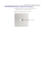
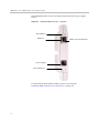
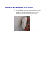
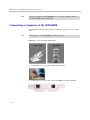
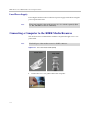
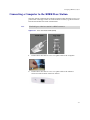
10 Configuring KIRK Wireless Server 6000 This section provides you with information on how to power up the KWS6000 and connect the unit to a computer. It also provides information on how to configure a KWS6000 through the web based Administration Page using either DHCP or static IP address. Note The KWS6000 is pre-configured to use a static IP address. This section includes information about: • “Powering up the KWS6000” on page 10-1 • “Connecting a Computer to the KWS6000” on page 10-2 • “Accessing the Web Based Administration Page” on page 10-3 • “Configuring a KIRK Wireless Server 6000 Using Static IP Address” on page 10-7 • “Configuring a KIRK Wireless Server 6000 Using DHCP” on page 10-15 • “Checking Indicators” on page 10-17 • “Making a Back-Up of the Configuration File” on page 10-17 Powering up the KWS6000 After installing the KWS6000 you need to power up the unit using: • Local power supply Power options for the KWS6000 is 48VDC, 1 W maximum when using local power supply. Local Power Supply Powering the KWS6000 with a local power supply can be done using the power input on the unit. 10–1 KIRK Wireless Server 6000 Installation and Configuration Guide The power supply for the KWS6000 is to be ordered separately (Part no. EU, UK and US version: 84642468). Note Connecting a Computer to the KWS6000 The KWS6000 communicates with the computer through a cross-over patch cable. The LAN port of the KWS6000 is a RJ45 connector. Note Figure 10-1 Cross-over patch cable (RJ45) 10–10 1 Connect the cross-over patch cable to the computer. 2 Connect the cross-over patch cable to the ETH port of the KWS6000. Configuring KIRK Wireless Server 6000 Accessing the Web Based Administration Page In order for your computer to communicate with the KWS6000 it is necessary to change the computer’s Internet Protocol Properties to have an IP address on the same subnet as the KWS6000. Below is shown an example on an IP address on the same subnet as the KWS6000 default IP address: • IP address: 192.168.0.2 • Sub-net mask: 255.255.255.0 How to Change Internet Protocol Properties using Windows XP 1 From the Start menu, point to Connect to and then click Show all connections. A Network Connections window appears. 10–3 KIRK Wireless Server 6000 Installation and Configuration Guide 2 Under Lan or High-Speed Internet, right-click on Local Area Connection and click Properties. A Local Area Connection Properties dialog box appears. Figure 10-2 Local Area Connection Properties dialog box 3 In the General tab, select Internet Protocol (TCP/IP), and then click Properties. An Internet Protocol (TCP/IP) Properties dialog box appears. Figure 10-3 Internet Protocol Properties dialog box 10–4 Configuring KIRK Wireless Server 6000 4 Click Use the following IP address, and then type 192.168.0.2 in the IP address field. 5 In the Subnet mask field, type 255.255.255.0. 6 Click OK. You can now reach the KWS6000 using a standard web browser. How to Access the Administration Page The web based Administration Page is accessed through a standard web browser. 1 Open a web browser. 2 In the browsers Address bar, type http://192.168.0.1, and then press ENTER. The KWS6000 Administration Page appears. Figure 10-4 Main page of the Administration Page for wireless server 10–5 KIRK Wireless Server 6000 Installation and Configuration Guide Entering a System User Name and Password First time you access the Administration Page, you need to log on with user name and a password. The default user name of the system is admin and the default password of the system is ip6000. It is strongly recommeded to change the password, refer to “Changing System User Name and Password” on page 15-2. Note Figure 10-5 Adm. Page: Enter Network Password dialog box 10–6 1 In the User Name field, type admin. 2 In the Password field, type ip6000. 3 Click OK. Configuring KIRK Wireless Server 6000 Configuring a KIRK Wireless Server 6000 Using Static IP Address This section describes how to configure a KWS6000 using static IP address. Note The KWS6000 is pre-configured to use a static IP address. It is strongly recommended to configure the KWS6000 using static IP address. Figure 10-6 KWS6000 installation For information on accessing the web based Administration Page, refer to “Accessing the Web Based Administration Page” on page 10-3. This section contains information about: • “General Configuration” on page 10-8 • “Wireless Server Configuration” on page 10-9 • “Built-In Media Resource Configuration” on page 10-10 • “SIP Configuration” on page 10-11 • “Security Configuration” on page 10-14 10–7 KIRK Wireless Server 6000 Installation and Configuration Guide General Configuration On the Configuration/General page you define IP, DNS and NTP settings for the KWS6000. 1 Click Configuration, and then click General. Figure 10-7 Adm. Page WS: Configuration/General page 2 Click Use Static IP Address. 3 In the IP Addr field, type the IP address of the KWS6000. 4 In the Netmask field, type a new network mask (optional). 5 Contact your system administrator for more information. In the Gateway field, type the IP address of the default gateway (optional). 6 The default gateway serves as an access point to another network. Contact your system administrator for more information. In the MTU field (Maximum Translation Unit), type the size of the largest packet, that your network protocol can transmit (optional). 7 In the Domain field, type the domain name of the system (optional). 8 In the Server field (under DNS - Domain Name System), type the IP address of the DNS server (optional). 9 In the Server field (under NTP - Network Time Protocol), type the IP address of the NTP server from which the system will obtain the current time (optional). 10 From the Time Zone list, select the wanted time zone (optional). 11 Check the UPnP (Universal Plug and Play) if you want to enable the support or to broadcast UPnP announcements. If the IP address of the device is unknown (forgotten or DHCP-assigned), UPnP can be used to easily identify it. 12 Click Save to save your general configuration data. 10–8 Configuring KIRK Wireless Server 6000 Wireless Server Configuration On the Configuration/Wireless Server page you configure the KWS6000 to allow subscription. If the system does not allow subscription, it is not possible to subscribe a handset. 1 Click Configuration, and then click Wireless Server. Figure 10-8 Adm. Page WS: Configuration/Media Resource page 2 Select the Subscription Allowed check box (optional). Note: If not selected, you cannot subscribe a handset. 3 Select the Authenticate Calls check box (optional). If selected, authentification will be performed every time a call is established. 4 The Encypt voice/data field (optional) specifies if dect encryption should be used for voice calls. It can be set as disabled, enabled or enforced (calls are terminated if the handset does not support encryption). Note: If dect encryption is enabled, the system requires base station firmware version PCS04_ or higher and it will not be possible to use repeaters on the system. Enabling encryption will additionally encrypt voice with an encryption key; a new key will be calculated for each new call. 5 Select the Autocreate Users check box (optional). If selected, after subscribing a handset, the system automatically will create a user for that specific handset, with the corresponding IPEI; afterwards, further details can be added to that user. 6 The System access code field (optional) specifies a system wide DECT access code required for subscribing handsets. The access code is from 0 to 8 decimal digits. Access codes assigned for specific users will override this setting. 7 Select the Send date and time check box (optional). This feature makes it possible to select whether the date/time should be visible in the handset or not. 10–9 Configuring KIRK Wireless Server 6000 8 The Username field (default - GW-DECT/admin) specifies the username required for applications to log in. 9 The New password field specifies the encrypted password required for applications to log in. In the New password again field it is required to retype the new password. 10 Select the Enable MSF (Message Service Function) check box (optional). It specifies if the MSF application interface (text messaging interface) is enabled and applications can connect. 11 Select the Enable XML-RPC check box (optional). It specifies if the XML-RPC application interface is enabled and applications can connect to the interface. Note: Existing MSF interface will not be affected. 12 Click Save. Built-In Media Resource Configuration On the Configuration/Media Resource page you configure the built-in Media Resource. 1 Click Configuration, and then click Media Resource. Figure 10-9 Adm. Page WS: Configuration/Media Resource page 10– 10 2 Click the Enabled field, if you want to activate the built-in media resource. 3 Click Save. Configuring KIRK Wireless Server 6000 SIP Configuration On the Configuration/SIP page you define general SIP settings, proxies, information about authentication, DTMF signalling, message waiting indication, media and call status. 1 Click Configuration, and then click SIP. Figure 10-10 Adm. Page WS: Configuration/SIP page 2 In the Local Port field, type the local port number. The default local port number is 5060. Note: The local port is the port on which the KWS6000 listens for incoming SIP-signalling. 10–11 KIRK Wireless Server 6000 Installation and Configuration Guide 3 The Transport field is set by default to UDP only, alternative is DNS SRV. UDP only would be selected if SIP signalling is sent through UDP, and only simple DNS is used for resolving IP addresses. DNS SRV would be selected if SIP signalling is sent through UDP, and DNS SRV is used for solving IP addresses. 4 In the Default Domain field, type the name of the domain. Note: If no user specific domain is configured, the handsets registered on the KWS6000 will use the default domain as the domain part of the SIP URI; e.g. John Doe <sip:[email protected]>. 5 Select Register each endpoint on separate port check box (optional). If enabled, it specifies that each user should use an individual UDP for its signaling; if disabled, all users should use the local port defined in the SIP configuration. 6 The Send all messages to current registrar check box (optional) specifies how requests outside a dialog are sent if a list of SIP servers is received via DNS SRV. If enabled, sends each request to the server currently holding the registration; if disabled, performs a DNS SRV lookup for each request and determines the destination from this. 7 In the Registation Expire(sec) field, type the number of seconds before a SIP registration will be renewed. The default value is 3600. 8 In the Max Forwards field, type a value (optional). It refers to the maximum number of proxies or gateways jumps, maximum number of times the SIP messages can be forwarded. The default value is 70. 9 The SIP type of service (TOS/Diffserv) field defines the Network Type of Service used for SIP messages. The default value is 96. 10 In the Proxy field, type a SIP proxy (optional). Note: The proxy is the SIP URI of the SIP-proxy. The KWS6000 will route all outgoing SIP signalling to the proxy, e.g. SIP registrations and outgoing calls. Along with the firmware version PCS04_ there was added support for entering more SIP proxies for failover and load balancing. This feature is relevant in a setup with more than one SIP proxy. 11 In the Default User field, type the user name. 12 In the Default Password field, type the password (optional). 10–12 Configuring KIRK Wireless Server 6000 Note: If no handset specific authentication user name/password is configured, handsets registered on the KWS6000 will use the default user name/password for authentication. 13 Select the Send as RTP (rfc2833) check box (Real-time Transport Protocol), for the keypad signalling to be sent as RTP packets with DTMF code (optional). 14 Offered rfc2833 payload type is DTMF payload type. The default value is 96. 15 Select the Send as SIP Info check box, if you want the keypad signalling sent as SIP INFO (optional). Note: If DTMF send as RTP and SIP info both are selected, some IP PBX will detect each information, and accordingly the DTMF signaling twice. 16 In the Tone Duration(msec) field, type the time length of the tone in miliseconds. The default value is 270. 17 Select the Enable Indication check box, if you want to handle MWI message (optional). 18 Select the Enable Subscription check box, if you want to subscribe to MWI indications from the SIP proxy (optional). 19 In the Subscription Expire(sec) field, type a value. The default value is 3600. 20 From the Packet Duration(msec) list, select between 10, 20 and 40. It defines the duration of the RTP media stream packets. 21 The Media type of service (TOS/Diffserv) has the default value 184. 22 The Port Range Start is the port start range for the RTP stream. The default value is 58000. 23 In the Codec priority fields, define the priorities of codecs. 24 The Require symmetric RTP check box defines whether the in and out RTP stream is symmetric or asymmetric. 25 The Play on-hold tone check box specifies if the handset should hear on-hold tone while during a call, one of the parties is put on hold. 26 Selecting the Display status messages check box call status messages will be displayed on the handset. 27 . '#' key ends overlap dialing specifies if pressing # while off hook dialing will dial the entered extension. 28 Click Save to save your SIP configuration data. 10–13 KIRK Wireless Server 6000 Installation and Configuration Guide Security Configuration It is possible to change the password for the unit from the Configuration/Security page. 1 Click Configuration, and then click Security (optional). Figure 10-11 Adm. Page: Configuration/Security page 2 In the Current password field, type the current password. 3 In the New username field, type a new username. 4 In the New password field, type a password. 5 In the New password again, type the password again. 6 Select Force secure HTTP (TLS) for secure connections. 7 Click Allow remote logging if it should be possible to perform remote logging (Useful in case of problem solving). 8 10–14 Click Save. Configuring KIRK Wireless Server 6000 Configuring a KIRK Wireless Server 6000 Using DHCP This section describes how to configure a KWS6000 using DHCP. Note It is strongly recommended to configure the KWS6000 using a static IP address. Note If the KWS6000 is configured using DHCP, it is necessary to assign a reservation for the device on the DHCP server. For information on accessing the web based Administration Page, refer to “Accessing the Web Based Administration Page” on page 10-3. This section contains information about: • “General Configuration” on page 10-15 • “Wireless Server Configuration” on page 10-16 • “Built-In Media Resource Configuration” on page 10-17 • “SIP Configuration” on page 10-17 • “Security Configuration” on page 10-17 General Configuration Using DHCP the device requests and obtains an available IP address from a DHCP server. The device also obtains other parameters such as the default gateway, subnet mask, DNS server, Time server and other IP parameters from the DHCP server. 1 Click Configuration, and then click General. 10–15 KIRK Wireless Server 6000 Installation and Configuration Guide Figure 10-12 Adm. Page WS: Configuration/General page 2 Click DHCP assigned. 3 In the MTU field (Maximum Transmission Unit), type the size of the 4 In the Domain field, type the domain name of the system (optional). 5 In the Server field (under DNS - Domain Name System), type the IP largest packet, that your network protocol can transmit (optional). address of the DNS server (optional). 6 In the Server field (under NTP - Network Time Protocol), type the IP address of the NTP server from which the system will obtain the current time (optional). 7 From the Time Zone list, select the wanted time zone (optional). 8 Check the UPnP (Universal Plug and Play) if you want to enable the support or to broadcast UPnP announcements. 9 Click Save to save your general configuration data. Wireless Server Configuration On the Configuration/Wireless Server page you configure the KWS6000 to allow subscription. If the system does not allow subscription, it is not possible to subscribe a handset. Refer to “Wireless Server Configuration” on page 10-9 for more information. 10–16 Configuring KIRK Wireless Server 6000 Built-In Media Resource Configuration On the Configuration/Media Resource page you configure the built-in Media Resource. Refer to “Built-In Media Resource Configuration” on page 10-10 for more information. SIP Configuration On the Configuration/SIP page you define general SIP settings, information about authentication, DTMF signalling, message waiting indication and media. Refer to “SIP Configuration” on page 10-11 for more information. Security Configuration It is possible to change the password for the unit from the Configuration/Security page. Refer to “Security Configuration” on page 10-14 for more information. Checking Indicators • Note Verify that the KWS6000/media resource LED indicator is continuously on, indicating that the KWS6000/media resource is functional. The LED will not be on before the base stations are configured. Making a Back-Up of the Configuration File For more information, refer to “Making a Back-Up of the Configuration File” on page 15-13. 10–17 KIRK Wireless Server 6000 Installation and Configuration Guide 10–18 11 Configuring KIRK Media Resources This section provides you with information on how to power up the media resource and connect the unit to a computer. It also provides information on how to configure a media resource through the web based Administration Page using either DHCP or static IP address. Note The media resource is pre-configured to use DHCP. It is recommended to configure the media resource using DHCP. This section includes information about: • “Powering up the KIRK Media Resource” on page 11-1 • “Connecting a Computer to the KIRK Media Resource” on page 11-2 • “Accessing the Web Based Administration Page” on page 11-3 • “Configuring a KIRK Media Resource Using DHCP” on page 11-6 • “Configuring a KIRK Media Resource Using Static IP Address” on page 11-7 • “Checking Indicators” on page 11-7 • “Making a Back-Up of the Configuration File” on page 11-8 Powering up the KIRK Media Resource After installing the media resources you need to power up the unit using: • Local Power Supply Power options for the KWS6000 is 48VDC, 1 W maximum when using local power supply. 11–1 KIRK Wireless Server 6000 Installation and Configuration Guide Local Power Supply Powering the media resource with a local power supply can be done using the power input on the unit. The power supply for the media resource is to be ordered separately (Part no. EU, UK and US version: 84642468). Note Connecting a Computer to the KIRK Media Resource The media resource communicates with the computer through a cross-over patch cable. The LAN port of the media resource is a RJ45 connector. Note Figure 11-1 Cross-Over Patch Cable (RJ45) 1 11–2 Connect the cross-over patch cable to the computer. Configuring KIRK Media Resources 2 Connect the cross-over patch cable to the ETH port of the media resource. Accessing the Web Based Administration Page In order for your computer to communicate with the KWS6000 it is necessary to change the computer’s Internet Protocol Properties to have an IP address on the same subnet as the KWS6000. Below is shown an example on an IP address on the same subnet as the Media Resource default IP address: • IP address: 192.168.0.2 • Sub-net mask: 255.255.255.0 How to Change Internet Protocol Properties using Windows XP 1 From the Start menu, point to Connect to and then click Show all connections. A Network Connections window appears. 11–3 KIRK Wireless Server 6000 Installation and Configuration Guide 2 Under Lan or High-Speed Internet, right-click on Local Area Connection and click Properties. A Local Area Connection Properties dialog box appears. Figure 11-2 Local Area Connection Properties dialog box 3 In the General tab, select Internet Protocol (TCP/IP), and then click Properties. An Internet Protocol (TCP/IP) Properties dialog box appears. Figure 11-3 Internet Protocol Properties dialog box 11–4 Configuring KIRK Media Resources 4 Click Use the following IP address, and then type 192.168.0.2 in the IP address field. 5 In the Subnet mask field, type 255.255.255.0. 6 Click OK. You can now reach the media resource using a standard web browser. How to Access the Administration Page The web based Administration Page is accessed through a standard web browser. 1 Open a web browser. 2 In the browsers Address bar, type http://192.168.0.1, and then press ENTER. The KWS6000 Administration Page appears. Figure 11-4 Main page of the Administration Page for media resource Entering a System User Name and Password First time you access the Administration Page, you need to log on with user name and a password. Note The default user name of the system is admin and the default password of the system is ip6000. It is strongly recommeded to change the password, refer to “Changing System User Name and Password” on page 15-20. 11–5 KIRK Wireless Server 6000 Installation and Configuration Guide Figure 11-5 Adm. Page: Enter Network Password dialog box 1 In the User Name field, type admin. 2 In the Password field, type ip6000. 3 Click OK. Configuring a KIRK Media Resource Using DHCP This section describes how to configure a media resource using DHCP. Note It is recommended to configure the media resource using DHCP. The media resource is pre-configured to use DHCP. If the KWS6000 is configured using a static IP address, it is possible to assign options to the DHCP server making it extremely easy to configure all media resources. For more information about assigning options to the DHCP server, refer to “Assigning DHCP Server Options” on page 9-2. Note 11–6 When assigning options to the DHCP server you do not need to configure the media resource through the Administration Page of the media resource. Just connect the media resource to the network. Configuring KIRK Media Resources Configuring a KIRK Media Resource Using Static IP Address This section describes how to configure a media resource using static IP address. This section contains information about: • “General Configuration” on page 11-7 • “Media Resource Configuration” on page 11-7 General Configuration On the Configuration/General page you define IP, DNS and NTP settings for the media resource. Refer to “General Configuration” on page 10-8 for a description. Media Resource Configuration On the Configuration/Media Resource page you configure the media resource. 1 Click Configuration, and then click Media Resource. Figure 11-6 Adm. Page Media Resource: Config./Media Resource page 2 In the Host field, type the address of the wireless server. 3 Click Save. Checking Indicators • Note Verify that the media resource LED indicator is continuously on, indicating that the media resource is functional. The LED will not be on before the base stations are configured. 11–7 12 Configuring KIRK Base Station This section provides you with information on how to connect the base station to a KWS6000 and how to configure the base station through the web based Administration Page using either DHCP or static IP address. Note The base station is pre-configured to use DHCP. It is strongly recommended to configure the base station using DHCP. This section includes information about: • “Powering up the KIRK Base Station” on page 12-1 • “Connecting a Computer to the KIRK Base Station” on page 12-2 • “Accessing the Web Based Administration Page” on page 12-3 • “Configuring a KIRK Base Station Using DHCP” on page 12-6 • “Configuring a KIRK Base Station Using Static IP Address” on page 12-9 • “Checking Indicators” on page 12-11 • “Making a Back-Up of the Configuration File” on page 12-11 Powering up the KIRK Base Station After installing the base station you need to power it up. The base station uses: • Power over Ethernet (PoE 802.3af). • Maximum power supply consumption is 3.0W (IEEE 802.3af class 1 device). Use a standard PoE adapter or a PoE-enabled port on a switch adhering to PoE 802.3af when connecting the base station to a PoE power source. 12–2 Configuring KIRK Base Station Connecting a Computer to the KIRK Base Station The base station communicates with the computer either through a cross-over patch cable or through a network with identical net mask, e.g. the IP address: 192.168.0.2 and Sub-net mask: 255.255.255.0. The LAN port of the base station is a RJ45 connector. Note Figure 12-1 Cross-Over Patch Cable (RJ45) 1 Connect the LAN cable or cross-over patch cable to the computer. 2 Connect the LAN cable or cross-over patch cable to the ethernet connector at the bottom of the base station. 12–1 Configuring KIRK Base Station Accessing the Web Based Administration Page In order for your computer to communicate with the KWS6000 it is necessary to change the computer’s Internet Protocol Properties to have an IP address on the same subnet as the KWS6000. Below is shown an example on an IP address on the same subnet as the base station default IP address: • IP address: 192.168.0.2 • Sub-net mask: 255.255.255.0 How to Change Internet Protocol Properties using Windows XP 1 From the Start menu, point to Connect to and then click Show all connections. A Network Connections window appears. 12–3 KIRK Wireless Server 6000 Installation and Configuration Guide 2 Under Lan or High-Speed Internet, right-click on Local Area Connection and click Properties. A Local Area Connection Properties dialog box appears. Figure 12-2 Local Area Connection Properties dialog box 3 In the General tab, select Internet Protocol (TCP/IP), and then click Properties. An Internet Protocol (TCP/IP) Properties dialog box appears. Figure 12-3 Internet Protocol Properties dialog box 12–4 Configuring KIRK Base Station 4 Click Use the following IP address, and then type 192.168.0.2 in the IP address field. 5 In the Subnet mask field, type 255.255.255.0. 6 Click OK. You can now reach the base station using a standard web browser. How to Access the Administration Page The web based Administration Page is accessed through a standard web browser. 1 Open a web browser. 2 In the browsers Address bar, type http://192.168.0.1, and then press ENTER. Note: The base station is pre-configured with the IP address: 192.168.0.1 through the ETH port. The Administration Page for the base station appears. Figure 12-4 Main page of the Administration Page for base station Entering a System User Name and Password First time you access the Administration Page, you need to log on with user name and a password. Note The default user name of the system is admin and the default password of the system is ip6000. It is strongly recommended to change the password, refer to “Changing System User Name and Password” on page 15-26. 12–5 KIRK Wireless Server 6000 Installation and Configuration Guide Figure 12-5 Adm. Page: Enter Network Password dialog box 1 In the User Name field, type admin. 2 In the Password field, type ip6000. 3 Click OK. Configuring a KIRK Base Station Using DHCP This section describes how to configure a base station using DHCP. Note It is strongly recommended to configure the base station using DHCP. The base station is pre-configured to use DHCP. If the KWS6000 is configured using a static IP address, it is possible to assign options to the DHCP server making it extremely easy to configure all base stations. For more information about assigning options to the DHCP server, refer to “Assigning DHCP Server Options” on page 9-2. For information on accessing the web based Administration Page, refer to “Accessing the Web Based Administration Page” on page 12-3. This section contains information about: 12–6 • “General Configuration” on page 12-7 • “Security Configuration” on page 12-7 • “Sync. Ways Configuration” on page 12-8 Configuring KIRK Base Station General Configuration On the General Configuration page you define DNS settings for the base station. 1 Click Configuration, and then click General. Figure 12-6 Adm. Page Base Station: Configuration/General page 2 3 Click DHCP assigned. In the MTU field (Maximum Translation Unit), type the size of the largest packet, that your network protocol can transmit (optional). 4 In the Domain field, type the domain name of the system (optional). 5 In the Server field (under DNS - Domain Name System), type the IP or to broadcast UPnP announcements. 6 Check the UPnP (Universal Plug and Play) if you want to enable the support address of the domain name (optional). Security Configuration It is possible to change the password for the unit. 1 Click Configuration, and then click Security (optional). Figure 12-7 Adm. Page Base Station: Configuration/Security page 12–7 KIRK Wireless Server 6000 Installation and Configuration Guide 2 In the Current password field, type the current password. 3 In the New username field, type a new username. 4 In the New password field, type a password. 5 In the New password again, type the password again. 6 Select Force secure HTTP (TLS) for secure connections. 7 Click Allow remote logging if it should be possible to log on to the system remotely (Useful in case of troubleshooting). 8 Click Save. Sync. Ways Configuration It is necessary to define the synchronization ways of the base station. 1 To define the sync. ways of the base station, open the Administration Page for the KWS6000. 2 Click Administration, and then click Base Station. Figure 12-8 Adm. Page WS:Administration/Base station page 3 12–8 Double-click on the relevant base station in the list. Configuring KIRK Base Station Figure 12-9 4 Adm. Page WS:Administration/Base station page In the RPN field (Radio Part Number), type the radio part number of the base station. The radio ID can be a number between 0 and 255. See your site planner. Note: The default value of the RPN is equal to the base station number. It is strongly recommended not to change this value. 5 It is possible to select Auto sync if you are deploying and want to find a sync way for the first base station. Note: Auto sync is only to be used in a deployment situation. When selecting Auto sync, radio part numbers in the Primary sync. (RPN) field and Secondary sync. (RPN) field are not taken into consideration. 6 In the Primary sync. (RPN) field, type the radio part number of the base station, you want to synchronize on. See your site planner. 7 In the Secondary sync. (RPN) field, type the radio part number of the base station, you want to synchronize on. See your site planner. 8 Click Save. To check the sync state of the base station, refer to “Sync State of Base Station” on page 15-29. Configuring a KIRK Base Station Using Static IP Address This section describes how to configure a base station using static IP address. For information on accessing the web based Administration Page, refer to “Accessing the Web Based Administration Page” on page 12-3. This section contains information about: 12–9 KIRK Wireless Server 6000 Installation and Configuration Guide • “General Configuration” on page 12-10 • “Base Station Configuration” on page 12-11 • “Security Configuration” on page 12-11 • “Sync. Ways Configuration” on page 12-11 General Configuration On the General Configuration page you define IP and DNS settings for the base station. 1 Click Configuration, and then click General. Figure 12-10 Adm. Page Base Station: Configuration/General page 2 Click Use static IP address. 3 In the IP addr field, type the IP address of the base station. 4 In the Netmask field, type 255.255.255.0. 5 In the Gateway field, type IP address of the default gateway (optional). The default gateway serves as an access point to another network. Contact your system administrator for more information. 6 In the MTU field (Maximum Translation Unit), type the size of the largest packet, that your network protocol can transmit (optional). 7 In the Domain field, type the domain name of the system (optional). 8 In the Server field (under DNS - Domain Name System), type the IP address of the domain name (optional). 9 Check the UPnP (Universal Plug and Play) if you want to enable the support or to broadcast UPnP announcements. 12–10 Configuring KIRK Base Station Base Station Configuration How to configure the base station: 1 Click Configuration, and then click Base station. Figure 12-11 Adm. Page Base Station: Configuration/Base station page 2 In the Host field, type the host name of the KWS6000. 3 Click Save. 4 Click Reboot to enable the configuration changes. Security Configuration It is possible to change the password for the unit. Refer to “Security Configuration” on page 12-7 for more information. Sync. Ways Configuration It is necessary to configure the sync. ways of the base station. Refer to “Sync. Ways Configuration” on page 12-8 for more information. Checking Indicators • Verify that the base station LED indicator is continuously on, indicating that the base station is functional. Making a Back-Up of the Configuration File For more information, refer to “Making a Back-Up of the Configuration File” on page 15-13. 12–11 KIRK Wireless Server 6000 Installation and Configuration Guide 12–12 13 KIRK Handset Registration and Subscription This section provides information about handset registration and subscription. You must register and subscribe a handset before you can use it. Note This section only describes how to register handsets on the KWS6000. You also need to register the users on the call handler. For registering users on the call handler, refer to the call handler user guide. When registering handsets you enter information about the handsets settings (such as; the handsets serial number (IPEI), name etc.) in the system database. When subscribing handsets you subscribe a registered handset to the system for usage. If the handset is not registered in the system database, subscription of the handset is not possible. This section includes information about: • “Registrering KIRK Handsets” on page 13-1 • “Subscribing KIRK Handsets” on page 13-3 Registering KIRK Handsets To register handsets you use the web based Administration Page of the KWS6000. Each handset in the wireless solution must be programmed with the serial number (IPEI) before it can operate. This serial number must be registered in the web based Administration Page of the KWS6000. Serial numbers are a unique fingerprint of each handset. The serial number is programmed into the handset during the manufacturing process and cannot be changed by field personnel. 13–1 KIRK Wireless Server 6000 Installation and Configuration Guide The KWS6000 does not provide any service to a handset whose serial number is not registered in the web based Administration Page. Note For more information about accessing the Administration Page, see “Accessing the Web Based Administration Page” on page 10-3. 1 Click Configuration and then click List Users. Figure 13-1 Adm. Page WS: Users/List Users page 2 Click New. Figure 13-2 Adm. Page WS: Users/List Users/Users page The data configured for each handset can be split into two categories. DECT data which is necessary for the correct handling of the DECT protocol stack. SIP data which is necessary for the handling of a SIP user agent. 3 13– 14 In the IPEI field, type the IPEI number (serial number) of the handset. The serial number consist of a five-digit handset type (manufacturer code) and a seven-digit handset number. KIRK Handset Registration and Subscription For more general information about the IPEI number (serial number) and how to retrieve it, refer to “Retrieving the Serial Number of the KIRK Handset” on page 8-12. 4 In the Access code field, type the authentication code (AC) (optional) The authentication code is a subscription password of a maximum of eight digits, defined by the technicians, and can be used when connecting the handset to a KWS6000. The authentication code is a subscription pin code for the individual handset. 5 In the Standby text field, type a text to be displayed when the handset is on hook (optional). 6 In the Username field, type the user part of a SIP URI, e.g. 1234 in John Doe<sip:[email protected]>. 7 In the Domain field, type the domain part of a SIP URI, e.g. somecompany.com in John Doe<sip:[email protected]> (optional). Note: If not configured, the default domain will be used. 8 In the Display name field, type the name to be displayed (caller ID), e.g. John Doe in John Doe<sip:[email protected]> (optional). 9 In the Authentication user field, type a user name (optional). 10 The user name will override the Default User field under SIP Configuration (refer to “SIP Configuration” on page 10-11). 11 In the Authentication password field, type a password (optional). The password will override the Default Password field under SIP Configuration (refer to “SIP Configuration” on page 10-11). 12 Select the Disabled check box if you want to disable the user you are editing. 13 Click Save to save the registration(s). Subscribing KIRK Handsets KIRK 3040 Handset A handset can be subscribed to more systems and will automatically log on to the relevant system. If a handset is subscribed to two or more systems, you can use Auto Login type A to change between the systems automatically. When to use Auto Login type A: 13–3 KIRK Wireless Server 6000 Installation and Configuration Guide • Auto Login A should only be used in separate systems without overlaps. If a handset loses signal from the system (the display showing Out of Range), then after 20 seconds the handset will start searching for an alternative system available from the Login list and automatically change to this system. Note: Using Auto Login A any call will be dropped when changing to an alternative system. This section provides information about: • “Subscribing Handsets” on page 13-5 • “Subscribing a Handset to Different Systems” on page 13-5 Note Using Auto Login A any call will be dropped when changing to an alternative system. Subscription of handsets requires the use of each registered handset. Note To make subscriptions, the system must allow subscriptions to be made (refer to “Wireless Server Configuration” on page 10-9). Some systems also require an Authentication Code (AC). If more than one system currently permits subscription, you will need to know the ID of the system (ARI code) to which you wish to subscribe. Authentication Codes and system ID’s (ARI codes) will be provided by the system administrator. Before subscribing handsets you need to ensure: 13–4 • that handset battery has been charged (“Charging Battery” on page 8-9). Low battery could cause subscription problems. • that the handsets have been registered to the system (“Registering KIRK Handsets” on page 13-1). KIRK Handset Registration and Subscription Subscribing Handsets 1 Press MENU - go to MENU LOGIN. 2 Press 3 - go to SUBSCRIPTION CREATE to subscribe to a system. 3 Press 3. The handset searches for the serial number of the system. 4 Use the < > keys to scroll between the IDs systems if there is more than one system available. 5 During subscription, the handset searches for free positions and performs subscription on the first free position. As soon as the correct serial number of the system appears in the display, press 3. The serial number is located on the label on the rear of the KWS6000. 6 Enter the AC (if required) using the keyboard, and press 3. An antenna symbol appears on the display to indicate a successful subscription. If not, the subscription has failed and the procedure must be retried. Subscribing a Handset to Different Systems The handset can be subscribed (connected) to a maximum of 10 different systems. To be able to log on to a system, subscription to the system must be established. Note Changing to another System Automatically Using Auto Login A Auto Login A should only be used when systems are separate, with no overlaps. Note 1 Press MENU - go to MENU LOGIN. 2 Press 3 - go to SELECT LOGIN. 3 Press 3 - go to SELECT LOGIN AUTO A. 4 Press 3. The handset automatically selects a system. The selected system is marked with an A. 13–5 KIRK Wireless Server 6000 Installation and Configuration Guide Changing to another System Manually If you would like to change to another system: 1 Press MENU - go to MENU LOGIN. 2 Press 3 - go to SELECT LOGIN to subscribe to a system. The actual chosen system is marked with an * or an A (if auto login is selected). 3 Press 3 - use the < > keys to scroll between the IDs of the different systems to find the system to which you want to connect. Under SELECT LOGIN only subscriptions display. Free positions do not display. 4 Press 3 to confirm. KIRK 4020/4040/4080 Handset A handset can be subscribed to more systems and will automatically log on to the relevant system. If a handset is subscribed to two or more systems, you can use Auto Login type A to change between the systems automatically. If a handset is subscribed to two systems only, you can use Auto Login type B to change between the systems automatically. When to use Auto Login type A: • Auto Login A should only be used in separate systems without overlaps. If a handset loses signal from the system (the display showing Out of Range), then after 20 seconds the handset will start searching for an alternative system available from the Login list and automatically change to this system. Note: Using Auto Login A any call will be dropped when changing to an alternative system. When to use Auto Login type B: • Auto Login B can be used in separate systems which are overlapping each other. As soon as the handset has measured a low RSSI signal 5 times in succession, it will start up the Auto Login type B procedure and change to an alternative system available. Note: Using Auto Login B any call will be dropped when changing to an alternative system. 13–6 KIRK Handset Registration and Subscription In some situations it is necessary to use Auto Login type B due to the following: — If two separate systems are sharing areas with common overlap, selecting Auto Login type A will result in poor performance as the handset will stay connected to the actual system it is subscribed to for as long as it can recognize a signal. Even if the bearer quality of the actual system is so bad that it cannot setup a connection, it is still not possible for the handset to change to alternative systems. Auto Login type B can enhance the performance for such configurations. Using Auto Login type B the handset is forced to switch from a system with bad bearer quality to one of the alternative systems available. To determine if it is necessary to log on to another system the handset is measuring the RSSI level. A number of measured low RSSI levels will force the handset to log on to the alternative system. This section provides information about: • “Subscribing Handsets” on page 13-8 • “Subscribing a Handset to Different Systems” on page 13-8 Note Subscription of handsets requires the use of each registered handset. Note To make subscriptions, the system must allow subscriptions to be made (refer to “Wireless Server Configuration” on page 10-9). Some systems also require an Authentication Code (AC). If more than one system currently permits subscription, you will need to know the ID of the system (ARI code) to which you wish to subscribe. Authentication Codes and system ID’s (ARI codes) will be provided by the system administrator. Before subscribing handsets you need to ensure: • that handset battery has been charged (“Charging Battery” on page 8-9). Low battery could cause subscription problems. • that the handsets have been registered to the system (“Registering KIRK Handsets” on page 13-1). 13–7 KIRK Wireless Server 6000 Installation and Configuration Guide Subscribing Handsets 1 Press MENU - go to MENU LOGIN. 2 Press 3 - go to SUBSCRIPTION CREATE to subscribe to a system. 3 Press 3. The handset searches for the serial number of the system. 4 Use the < > keys to scroll between the IDs systems if there is more than one system available. During subscription, the handset searches for free positions and performs subscription on the first free position. 5 As soon as the correct serial number of the system appears in the display, press 3. The serial number is located on the label on the rear of the KWS6000. 6 Enter the AC (if required) using the keyboard, and press 3. An antenna symbol appears on the display to indicate a successful subscription. If not, the subscription has failed and the procedure must be retried. Subscribing a Handset to Different Systems The handset can be subscribed (connected) to a maximum of 10 different systems. To be able to log on to a system, subscription to the system must be established. Note Changing to another System Automatically Using Auto Login A Auto Login A should only be used when systems are separate, with no overlaps. Note 1 Press MENU - go to MENU LOGIN. 2 Press 3 - go to SELECT LOGIN. 3 Press 3 - go to SELECT LOGIN AUTO A. 4 Press 3. The handset automatically selects a system. The selected system is marked with an A. 13–8 KIRK Handset Registration and Subscription Changing to another System Automatically Using Auto Login B Auto Login B can be used in separate systems which are overlapping each other. Note 1 Press MENU – go to MENU LOGIN. 2 Press 3 – go to SELECT LOGIN. 3 Press 3 – go to SELECT LOGIN AUTO B. 4 Press 3. The handset automatically selects a system. The selected system is marked with a B. Changing to another System Manually If you would like to change to another system: 1 Press MENU - go to MENU LOGIN. 2 Press 3 - go to SELECT LOGIN to subscribe to a system. The actual chosen system is marked with an * or an A (if auto login is selected). 3 Press 3 - use the < > keys to scroll between the IDs of the different systems to find the system to which you want to connect. Under SELECT LOGIN only subscriptions display. Free positions do not display. 4 Press 3 to confirm. KIRK 5020/5040 Handset A handset can be subscribed to more systems and will automatically log on to the relevant system. If a handset is subscribed to two or more systems, you can use Auto Login type A to change between the systems automatically. When to use Auto Login type A: • Auto Login A should only be used in separate systems without overlaps. If a handset loses signal from the system (the display showing a no signal icon), then after 20 seconds the handset will start searching for an alternative system available from the Login list and automatically change to this system. Note: Using Auto Login A any call will be dropped when changing to an alternative system. 13–9 KIRK Wireless Server 6000 Installation and Configuration Guide This section provides information about: • “Creating Login (Subscribing Handset)” on page 13-10 • “Subscribing a Handset to Different Systems” on page 13-11 Note Subscription of handsets requires the use of each registered handset. Note To make subscriptions, the system must allow subscriptions to be made (refer to “Wireless Server Configuration” on page 10-9). Some systems also require an Authentication Code (AC). If more than one system currently permits subscription, you will need to know the ID of the system (ARI code) to which you wish to subscribe. Authentication Codes and system ID’s (ARI codes) will be provided by the system administrator. Before subscribing handsets you need to ensure: • that handset battery has been charged (“Charging Battery” on page 8-9). Low battery could cause subscription problems. • that the handsets have been registered to the system (“Registering KIRK Handsets” on page 13-1). Creating Login (Subscribing Handset) To create a login, the system must allow subscriptions to be made. Some systems also require an Authentication Code (AC). If more than one system currently permits subscription, you will need to know the ID of the system to which you want to subscribe. Authentication Codes and system ID’s will be provided be the system administrator. You can subscribe up to 10 systems (create 10 logins). 13–10 1 Press Menu to enter main menu. 2 Scroll to Settings and press Select. 3 Scroll to Advanced and press Select. 4 Scroll to Login and press Select. 5 Scroll to Create login and press Select. The handset will start searching for a system. 6 Scroll to the found system and press Select. 7 Enter an AC Code and press Ok to connect to the system. 8 Press Ok. KIRK Handset Registration and Subscription Subscribing a Handset to Different Systems The handset can be subscribed (connected) to a maximum of 10 different systems. To be able to log on to a system, subscription to the system must be established. Note Changing to another System Automatically Using Auto Login A Note Auto Login A should only be used when systems are separate, with no overlaps. Note To activate Auto login your handset must be subscribed to at least two systems. 1 Press Menu to enter main menu. 2 Scroll to Settings and press Select. 3 Scroll to Advanced and press Select. 4 Scroll to Login and press Select. 5 Scroll to Auto login and press Select. 6 If Off is selected, press Change to select On. 7 Press R to return to standby mode. The handset automatically selects a system. The selected system is marked with an A. Changing to another System Manually If you would like to change to another system: 1 Press Menu to enter main menu. 2 Scroll to Settings and press Select. 3 Scroll to Advanced and press Select. 4 Scroll to Login and press Select. 5 Scroll to Select login and press Select. 6 Scroll to the desired login and press Select. 13–11 KIRK Wireless Server 6000 Installation and Configuration Guide 13–12 14 KIRK Handset Management This section provides information about handset management such as viewing handset configuration, deregistering handsets and changing user configurations using the web based Administration Page. It also provides information about unsubscribing handsets, exporting/restoring/importing handset registration data and handset adjustment. For more information about accessing the Administration Page, refer to “Accessing the Web Based Administration Page” on page 10-3. This section includes information about: • “Viewing Handset/User Configuration” on page 14-2 • “Searching for Handset/User Information” on page 14-2 • “Unsubscribing KIRK Handsets” on page 14-3 • “Removing KIRK Handsets from the List (Deregistering)” on page 14-4 • “Changing User Configurations” on page 14-6 • “Exporting Handset Registration Data” on page 14-7 • “Restoring Handset Registration Data” on page 14-9 • “Importing Handset Registration Data - CSV Format” on page 14-11 • “Adjusting the KIRK Handset” on page 14-13 14–1 KIRK Wireless Server 6000 Installation and Configuration Guide Viewing Handset/User Configuration Through the web based Administration Page, it is possible to view all the user configurations of the wireless system. 1 Click Users, and then click List Users. Figure 14-1 Adm. Page WS: Users/List Users page Searching for Handset/User Information Through the web based Administration Page, it is possible to search for a registered handset/user in the system. 1 Click Users, and then click List Users. Figure 14-2 Adm. Page WS: Users/List Users page 2 14–2 Type the beginning of a user, display name or IPEI to search for in the text field, and then click Search. KIRK Handset Management Removing KIRK Handsets from the List (Deregistering) You can deregister handsets from KWS6000. This is necessary when: • you must replace the handset due to loss or breakage. • you want to assign the handset to a user with a different telephone number. 1 Click Users, and then click List Users. Figure 14-3 Adm. Page WS: Users/List Users page 2 Type the beginning of a number or name to search for in the text field, and then click Search or select the handset in question by clicking on the user information. The following page appears. Figure 14-4 Adm. Page WS: Users/List Users/User page 3 Click Delete to remove the registration. A warning box appears. 14– 15 KIRK Wireless Server 6000 Installation and Configuration Guide Figure 14-5 Warning box 4 Click OK. Changing User Configurations You can change user configurations, such as the AC (authentication code) using the web based Administration Page. 1 Click Users, and then click List Users. Figure 14-6 Adm. Page WS: Users/List Users page 2 Type the beginning of a number or name to search for in the text field, and then click Search or select the handset in question by clicking on the user information. The following page appears. 14– 16 KIRK Handset Management Figure 14-7 Adm. Page WS: Users/List Users/User page 3 Change settings, and then click Save. 14– 17 KIRK Wireless Server 6000 Installation and Configuration Guide Exporting Handset Registration Data You can export handset registration data using the web based Administration Page. 1 Click Users, and then click Import/Export. Figure 14-8 Adm. Page WS: Users/Import/Export page 2 Under Export User Data do one of the following: a To save user data in CSV format, click the Save button. b To save user data in XML format, click the Save button. You can export handset registration data also using the full system backup facility. Instead of separate backups of configuration, users etc. everything is in one backup and it is optional how much is restored. 1 Click Administration, and then click Backup. Figure 14-9 14– 18 Adm. Page WS: Admin/Backup page KIRK Handset Management 2 Under Backup, click the Save button for full system backup. Figure 14-10 3 File download window Click the Save button and choose the folder where you want to save the fullbackup.tar file and start the download. Figure 14-11 Downloading process of the fulbackup file 14– 19 KIRK Wireless Server 6000 Installation and Configuration Guide Restoring Handset Registration Data You can restore handset registration data using the web based Administration Page. It is possible to restore a user database with subscriptions and to restore a user database separately from subscriptions (configuration data only). 1 Click Administration, and then click Backup. Figure 14-12 Adm. Page WS: Admin/Backup page 2 Under Restore do one of the following: a To restore configuration data, select the User database checkbox. b To restore user data with subscriptions, select the DECT subscriptions checkbox. 3 A warning window will appear. Figure 14-13 Warning window 4 14– 20 Click OK. KIRK Wireless Server 6000 Installation and Configuration Guide 5 In the Restore field, you can also Browse for the backup file and select it and then select the Restore button in order to restore the desired configurations out of the full system backup file. 6 Click Reboot. The system is rebooted. This can take a few minutes. 14–10 KIRK Handset Management Importing Handset Registration Data - CSV Format You can import handset registration data in CSV format. To be able to import the data correctly, you must create a file containing the following information and punctuation: #IPEI,access code,standby text,username,domain,displayname,authenticate user,authenticate password,local number If you want to leave out some of the information, e.g. standby text, you must keep the commas, e.g.:#IPEI,access code,,username,domain,displayname,authenticate user,authenticate password,local number. Note Figure 14-14 1 Example of Handset Registration Data in CSV Format Click Users, and then click Import/Export. Figure 14-15 Adm. Page WS: Users/Import/Export page 14–11 KIRK Wireless Server 6000 Installation and Configuration Guide 2 Under Import User Data, click Browse to find the CSV file with handset registration data. A Choose File dialog box appears. Figure 14-16 Adm. Page: Choose File dialog box Note 14–12 3 Select the file in question, and then click Open. 4 Click Load. 5 Click OK. It is not possible to import handset registration data already registered in the system. KIRK Handset Management 14–13 15 System Management This section provides you with information about the web based Administration Page of the KWS6000. The section describes how it is used for system management. For information about using the Service Tool for system management of repeaters and handsets, refer to “Programming the KIRK Repeater with the Service Tool” on page 6-9 for information about repeater programming and “Adjusting the KIRK Handset with the Service Tool” on page 14-14 for information about handset adjustment. For information on accessing the web based Administration Page, refer to “Accessing the Web Based Administration Page” on page 10-3. Through the web based Administration Page of the KWS6000 it is possible to define and view different settings of the system, reading statistics, making a backup of configuration file, updating system software, and resetting the system. This section includes information about system management of: • “KIRK Wireless Server 6000” on page 15-2 • “KIRK Media Resource” on page 15-20 • “KIRK Base Station” on page 15-26 15–1 KIRK Wireless Server 6000 Installation and Configuration Guide KIRK Wireless Server 6000 This section includes information about: • “Changing System User Name and Password” on page 15-2 • “Reading System Information” on page 15-3 • “Reading Statistics” on page 15-7 • “Making a Back-Up of the Configuration File” on page 15-13 • “Restoring Configuration File” on page 15-15 • “Updating the KIRK Wireless Server 6000” on page 15-16 • “Restarting the KIRK Wireless Server 6000” on page 15-18 Changing System User Name and Password Ensure that you have opened the Administration Page of the KWS6000. Note From the Administration Page it is possible to change the user name and password for the system. 1 Click Configuration, and then click Security. Figure 15-1 Adm. Page WS: Configuration/Security page 15–16 2 In the Current password field, type the current password. 3 In the New user name field, type a user name. 4 In the New password field, type a new password 5 In the New password again field, type the new password again to confirm it. 6 Click Save to change the password. System Management Reading System Information Under Status it is possible to get general information about hardware version, firmware and message logging. This information is useful in case of problem solving. Accessing the Administration Page of the wireless server provides an overview of the solution, e.g. how the base stations are working. Note Ensure that you have opened the Administration Page of the KWS6000. This section provides information about: • “General Status Information” on page 15-3 • “Logs Information” on page 15-4 • “Wireless Server Information” on page 15-5 • “Packet Capture Information” on page 15-6 General Status Information This page provides general system information such as hardware, firmware and OS Status information. 1 Click Status, and then click General. Figure 15-2 Adm. Page WS: Status/General page On the Status/General page you can read information about: — the used firmware and hard ware — Mac Address (serial number) of the system — NTP Server; from which IP address the system receives its time information — Time; time information - if a time server is valid 15–3 KIRK Wireless Server 6000 Installation and Configuration Guide Logs Information This page provides logs information such as media resource connection, base station connection and different types of status. 1 Click Status, and then click Logs. Figure 15-3 Adm. Page WS: Status/Logs page 2 From the Display filter list you can select between emergency, critical, error, warning, notices, info or debug depending on the logs you want to see. The different types of status are: — Emergency is used for errors causing the system to malfunction for all calls — Critical is used for events which do not occur under normal operation, which cause major malfunction. E.g. events that result in a permanent state of malfunction for a handset — Error is used for events which do not occur under normal operation, which cause minor malfunction. E.g. events that result in a lost call — Warning is used for events which do not occur under normal operation, which may cause malfunction. E.g. events that may result in a lost call — Notice is used for events which occur under normal operation and are relevant for an administrator. E.g. KGAP started — Information is used for events which occur under normal operation and may be relevant for an administrator. E.g new RFP connection — Debug is used for debug information 15–4 System Management 3 Click Save if you want to save the logs in a file. A Save As dialog box appears. Figure 15-4 Adm. Page: Save As dialog box 4 Indicate in which folder and under what name the file should be saved, and then click Save. It is now possible to send the log files to authorized technicians for further support and problem solving. Wireless Server Information This page provides information about the firmware version and ARI code of the KWS6000. 1 Click Status, and then click Wireless Server. Figure 15-5 Adm. Page WS: Status/WS page 15–5 KIRK Wireless Server 6000 Installation and Configuration Guide Packet Capture This page provides tracing the packets transmitted during the calls, messaging etc. 1 Click Status, and then click Packet Capture. Figure 15-6 Adm. Page WS: Status/Packet Capture page 15–6 2 Under Filters choose a single or several filters. (Capture SIP, Capture external RTP, Capture internal RTP, Capture MSF, Capture everything, Custom filter). 3 Under Status select the Start Button to begin capturing, Stop to stop capturing and finally the Save button to save the trace into the desired destination folder. KIRK Wireless Server 6000 Installation and Configuration Guide Reading Statistics Under Statistics, it is possible to read statistic information about the KWS6000, media resource, base station, and calls, handovers and abnormal releases in the system. You get an overall overview of how the system is running. Ensure that you have opened the Administration Page of the KWS6000. Note This section provides information about: • “Wireless Server” on page 15-7 • “Media Resource” on page 15-8 • “Base Station” on page 15-9 • “Active Calls” on page 15-9 • “Abnormal Releases” on page 15-9 • “Traffic Distribution” on page 15-10 Wireless Server This page is useful to get information about traffic on the KWS6000 such as voice call traffic and message call traffic and it provides a summary of subscription and handover statistics. It also provides information about the traffic load (Erlang) of the installation which is useful when determining the number of media resources needed. 1 Click Statistics, and then click Wireless Server. 15–7 System Management Figure 15-7 Adm. Page WS: Statistics/WS page 2 Click Reset Statistics if you want to delete all statistic traffic information. A warning message appears. Figure 15-8 Warning message 3 Click OK. Media Resource This page is useful to get information about the media resource. 1 Click Statistics, and then click Media Resource. Figure 15-9 15–8 Adm. Page WS: Statistics/Media Resource page KIRK Wireless Server 6000 Installation and Configuration Guide Base Station This page is useful to get statistic information about the base station. 1 Click Statistics, and then click Base Station. Figure 15-10 Adm. Page WS: Statistics/Base Station page Active Calls This page is useful to get statistic information about active calls in the KWS6000 installation. 1 Click Statistics, and then click Active Calls. Figure 15-11 Adm. Page WS: Statistics/Active Calls page Abnormal Releases This page is useful to get statistic information about abnormal releases in a KWS6000 installation. 1 Click Statistics, and then click Abnormal Releases. 15–9 System Management Figure 15-12 Adm. Page WS: Statistics/Abnormal Releases page Traffic Distribution This page is useful to get statistic information about traffic distribution during the last 24 hours in a KWS6000 installation. 1 Click Statistics, and then click Traffic Distribution. Figure 15-13 Adm. Page WS: Statistics/Traffic Distribution page 15– 10 KIRK Wireless Server 6000 Installation and Configuration Guide Provisioning configuration Specifies the static boot server URL from where the KWS will retrieve configuration information. It is optional to specify a protocol. If the protocol is not specified the KWS will default to tftp. Note Ensure you have opened the Administration Page ofconsult the KWS6000. For morethat detailed explanations concerning provisioning, the Provisioning_guide_KWS300_6000. 1 Click Configuration, and then Provisioning. Figure 15-14 Adm. Page WS: Config/Provisioning page Clusters Clusters are relevant for de-centralized installations. Cluster handling refers to the mechanism of configuring a DECT wireless network formed by distributed remote areas. 1 Click Administration, and then select Clusters. Create a cluster. Figure 15-15 Adm. Page WS: Admin/Clusters page 15–11 KIRK Wireless Server 6000 Installation and Configuration Guide Phonebook configuration The Phonebook application offers a centralized phonebook. The formats supported for the phonebook are CSV-file and LDAP. Note For information on configuring the phonebook using a CSV formatted file and or using an LDAP server, refer to Configuring the Phonebook. 1 Click Administration and then click Phonebook. Figure 15-16 Adm. Page WS: Admin/Phonebook configuration page 15–12 KIRK Wireless Server 6000 Installation and Configuration Guide Making a Back-Up of the Configuration File This section provides information about saving the configuration data of the KWS6000, registration and subscription data of the handset and system information. When saving the configuration data you have an overall overview of the KIRK Wireless Server which is useful in case of problem solving. Note Ensure that you have opened the Administration Page of the KWS6000. You can export configuration data using the full system backup facility. Instead of separate backups of configuration, users etc. everything is in one backup and it is optional how much is restored. 1 Click Administration, and then click Backup. Figure 15-17 Adm. Page WS: Admin/Backup page 2 Under Backup, click the Save button for full system backup. Figure 15-18 File download window 15–13 System Management 3 Click the Save button and choose the folder where you want to save the Full backup.tar file and start the download. Figure 15-19 Downloading process of the fulbackup file You can also export configuration data using the Import/Export feature. 1 Click Configuration, and then click Import/Export. Figure 15-20 Adm. Page WS: Config/Import/Export 2 15–14 Under Export configuration, select the Save button. Further on, you can choose the destination folder you want to save the configuration file. KIRK Wireless Server 6000 Installation and Configuration Guide Restoring Configuration File You can restore configuration data using the web based Administration Page, along with the other configured features included in the full system backup file, or separately from them. 1 Click Administration, and then click Backup. Figure 15-21 Adm. Page WS: Admin/Backup page 2 Under Restore, select Configuration. 3 A warning window will appear. Figure 15-22 Warning window 4 Click OK. 5 In the Restore field, you can also Browse for the backup file and select it and then select the Restore button in order to restore the desired configurations out of the full system backup file. 6 Click Reboot. The system is rebooted. This can take a few minutes. 15–15 System Management Updating the KIRK Wireless Server 6000 The software of the KWS6000 can be updated. To update the software you load a file to the system. Contact your distributor for newest software. Ensure that you have opened the Administration Page of the KWS6000. Note Updating KIRK Wireless Server 6000 Firmware 1 Click Firmware, and then click Wireless Server. Figure 15-23 Adm. Page WS: Firmware/WS page 2 Click Browse. A Choose File dialog box appears. Figure 15-24 Adm. Page: Choose File dialog box 3 Select the file in question, and then click Open. 4 Click Update. Wait until the system has finished updating. Warning: Do not cut power. 15–16 KIRK Wireless Server 6000 Installation and Configuration Guide Figure 15-25 Adm. Page: Firmware Update Progress Bar 5 Optionally, you can block new calls during a firmware update by clicking Administration, and then Wireless Server. Figure 15-26 Adm. Page WS: Administration/WS page Under Service Status click Block. 6 Click Reboot to update the KWS6000 firmware. 7 If you have blocked new calls during a firmware update, enable new calls again by clicking Administration, then Wireless Server and then clicking Allow. 15–17 System Management Restarting the KIRK Wireless Server 6000 Some configuration changes require a restart in order to take effect. A reset restarts the KWS6000 software. Note 15–18 Ensure that you have opened the Administration Page of the KWS6000. KIRK Wireless Server 6000 Installation and Configuration Guide You must restart the system after the following procedures: 1 • configuring • uploading configuration data • uploading firmware Click Administration, and then click Wireless Server. Figure 15-27 Adm. Page WS: Administration/WS page 2 After Wireless Server Uptime click Reboot. 15–19 System Management KIRK Media Resource This section includes information about: • “Changing System User Name and Password” on page 15-20 • “Reading System Information” on page 15-21 • “Reading Statistics” on page 15-24 • “Updating the KIRK Media Resource Firmware” on page 15-24 Changing System User Name and Password Note Ensure that you have opened the Administration Page of the media resource. From the Administration Page it is possible to change the user name and password for the system. 1 Click Configuration, and then click Security. Figure 15-28 Adm. Page Media Resource: Configuration/Security page 15–20 2 In the Current password field, type the current password. 3 In the New user name field, type a user name. 4 In the New password field, type a new password 5 In the New password again field, type the new password again to confirm it. 6 Click Save to change the password. KIRK Wireless Server 6000 Installation and Configuration Guide Reading System Information Under Status it is possible to get general information about hardware version, firmware and message logging. This information is useful in case of problem solving. Note Ensure that you have opened the Administration Page of the media resource. This sections provides information about: • “General Status Information” on page 15-21 • “Logs Information” on page 15-22 General Status Information This page provides general system information such as hardware, firmware and OS Status information. 1 Click Status, and then click General. Figure 15-29 Adm. Page Media Resource: Status/General page 15–21 System Management On the Status/General page you can read information about: — the used firmware and hard ware — Mac Address (serial number) of the system — NTP Server; from which IP address the system receives its time information — Time; time information - if a time server is valid Logs Information This page provides logs information such as media resource connection, base station connection and different types of status. Figure 15-30 Adm. Page Media Resource: Status/Logs page 15–22 KIRK Wireless Server 6000 Installation and Configuration Guide 1 From the Display filter list you can select between emergency, critical, error, warning, notice, info or debug depending on the logs you want to see. The different types of status are: — Emergency is used for errors causing the system to malfunction for all calls — Critical is used for events which do not occur under normal operation, which cause major malfunction. E.g. events that result in a permanent state of malfunction for a handset — Error is used for events which do not occur under normal operation, which cause minor malfunction. E.g. events that result in a lost call — Warning is used for events which do not occur under normal operation, which may cause malfunction. E.g. events that may result in a lost call — Notice is used for events which occur under normal operation and are relevant for an administrator. E.g. KGAP started — Information is used for events which occur under normal operation and may be relevant for an administrator. E.g new RFP connection — Debug is used for debug information 2 Click Status, and then click Logs. 3 Click Save if you want to save the logs in a file. A Save As dialog box appears. Figure 15-31 Adm. Page: Save As dialog box 15–23 4 System Management Indicate in which folder and under what name the file should be saved, and then click Save. It is now possible to send the log files to authorized technicians for further support and problem solving. 15–24 KIRK Wireless Server 6000 Installation and Configuration Guide Reading Statistics Statistic information about the media resource is retrieved from the Administration Page of the KWS6000. For more information about reading statistics for the media resource, refer to “Reading Statistics” on page 15-7. Updating the KIRK Media Resource Firmware The software of the media resource can be updated. To update the software you load a file to the system. Contact your distributor for newest software. Updating KIRK Media Resource Firmware Note Ensure that you have opened the Administration Page of the media resource. 1 Click Firmware, and then click Media Resource. Figure 15-32 Adm. Page Media Resource: Firmware/Media Resource page Figure 15-33 Adm. Page WS: Firmware/Media Resource page 2 Click Browse. A Choose File dialog box appears. 15–25 System Management Figure 15-34 Adm. Page: Choose File dialog box 3 Select the file in question, and then click Open. The file to select has the extension .bin. 4 Click Update. Wait until the system has finished uploading. Figure 15-35 Adm. Page: Firmware Update Progress Bar 5 Optionally, you can block new calls during a firmware update by clicking Administration (Administration Page of KWS6000), and then Wireless Server. Figure 15-36 Adm. Page WS: Administration/WS page Under Service Status click Block. 15–26 6 When the update is finished, click Reboot to execute the changes. 7 If you have blocked new calls during a firmware update, enable new calls again by clicking Administration (Administration Page of KWS6000), then Wireless Server and then clicking Allow. KIRK Wireless Server 6000 Installation and Configuration Guide KIRK Base Station This section includes information about: • “Changing System User Name and Password” on page 15-26 • “Reading System Information” on page 15-27 • “Reading Statistics” on page 15-29 • “Sync State of Base Station” on page 15-29 • “Updating the KIRK Base Station Firmware” on page 15-31 Changing System User Name and Password Ensure that you have opened the Administration Page of the base station. Note From the Administration Page it is possible to change the user name and password for the system. 1 Click Configuration, and then click Security. Figure 15-37 Adm. Page Base Station: Configuration/Security page 2 In the Current password field, type the current password. 3 In the New user name field, type a user name. 4 In the New password field, type a new password 5 In the New password again field, type the new password again to confirm it. 6 Click Save to change the password. 15–27 System Management Reading System Information Under Status it is possible to get general information about hardware version, firmware and message logging. This information is useful in case of problem solving. Ensure that you have opened the Administration Page of the base station. Note This sections provides information about: • “General Status Information” on page 15-27 • “Logs Information” on page 15-28 General Status Information This page provides general system information such as hardware, firmware and OS Status information. 1 Click Status, and then click General. Figure 15-38 Adm. Page Base Station: Status/General page On the Status/General page you can read information about: 15–28 • the used firmware and hard ware • Mac Address (serial number) of the system • NTP Server; from which IP address the system receives its time information • Time; time information - if a time server is valid KIRK Wireless Server 6000 Installation and Configuration Guide Logs Information This page provides logs information such as media resource connection, base station connection and different types of status. The different types of status are: — Emergency is used for errors causing the system to malfunction for all calls — Critical is used for events which do not occur under normal operation, which cause major malfunction. E.g. events that result in a permanent state of malfunction for a handset — Error is used for events which do not occur under normal operation, which cause minor malfunction. E.g. events that result in a lost call — Warning is used for events which do not occur under normal operation, which may cause malfunction. E.g. events that may result in a lost call — Notice is used for events which occur under normal operation and are relevant for an administrator. E.g. KGAP started — Information is used for events which occur under normal operation and may be relevant for an administrator. E.g new RFP connection — Debug is used for debug information 1 Click Status, and then click Logs. Figure 15-39 Adm. Page Base Station: Status/Logs page 2 From the Display filter list you can select between emergency, critical, error, warning, notices, info or debug depending on the logs you want to see. 3 Click Save if you want to save the logs in a file. A Save As dialog box appears. 15–29 System Management Figure 15-40 Adm. Page: Save As dialog box 4 Indicate in which folder and under what name the file should be saved, and then click Save. It is now possible to send the log files to authorized technicians for further support and problem solving. Reading Statistics Statistic information about the base station is retrieved from the Administration Page of the KWS6000. For more information about reading statistics for the base station, refer to “Reading Statistics” on page 15-7. Sync State of Base Station You can get information about the synchronization state of the base station the uptime and to which radio unit it synchronizes on. This is useful when you want to get an overview of the base stations and in case of problem solving. Note 15–30 Information about the synchronization state of the base station is retrieved from the Administration Page of the KWS6000. System Management Checking Sync State Ensure that you have opened the Administration Page of the KWS6000. Note 1 Click Administration, and then click Base Station. Figure 15-41 Adm. Page WS: Administration/Base station (WS) page Figure 15-42 Sync States of Base Station - Colour Description 2 Check the sync state of the base stations: — If marked with blue: Free running (Sync Master) — If marked with green: Synchronized to primary (Primary Sync Master) — If marked with yellow: Synchronized to alternative (Alternative Sync Master) — If marked with red: Searching (not in sync with any radio unit) — If marked with grey: Unknown (not connected - base station removed from installation) Note 15–30 When double-clicking on a base station in the list, you can check the the RSSI values of the base stations it is synchronizing on (Primary sync/Secondary (Alternative) sync). KIRK Wireless Server 6000 Installation and Configuration Guide Updating the KIRK Base Station Firmware The software of the base station can be updated. To update the software you load a file to the system. Contact your distributor for newest software. Note The base station firmware can be updated both from the Administration Page of the base station or the KWS6000. Updating KIRK Base Station Firmware Note Ensure that you have opened the Administration Page of the KWS6000. You can specify a range of base stations to be updated with new firmware. 1 Click Firmware, and then click Base Station. Figure 15-43 Adm. Page WS: Firmware/Base station page Figure 15-44 Adm. Page BS: Firmware/Base station page 2 In the Firmware file field, click Browse. A Choose File dialog box appears. Figure 15-45 Adm. Page: Choose File dialog box 15–31 System Management 3 Select the file in question, and then click Open. The file to select has the extension .bin. 4 In the Start RFP No field, type the number of the first base station to be updated. Note: You can check base station numbers under Administration/Base station. 5 In the End RFP No field, type the number of the last base station to be updated. 6 Click Update. Wait until the system has finished uploading. All base stations in the range specified are updated. Note: You can check the update status under Administration/Base station while the update is progressing. Each update takes approximately 30 seconds. Figure 15-46 Update base station firmware page 7 Optionally, you can block new calls during a firmware update by clicking Administration, and then Wireless Server. Figure 15-47 Adm. Page WS: Administration/WS page Under Service Status click Block. 15–32 KIRK Wireless Server 6000 Installation and Configuration Guide 8 When the update is finished, reboot the base stations to make execute the changes. Note: Make sure you reboot the base stations – not the KWS6000 server itself. To reboot the base stations go to Firmware -> Base Stations -> select the base station range which shall be rebooted and click the Reboot base station button. 15–33 KIRK Wireless Server 6000 Installation and Configuration Guide 16 Application integration With a KIRK DECT solution it is possible to make applications which send text messages to any messaging compatible KIRK DECT handsets. This makes it possible to create solutions with specific functionality targeting specific verticals. Examples on such vertical applications are: • • • • Integration to nurse call systems Fire alert broadcast to all handsets Technical info send as notification Escalated alarms which require acknowledge. KWS6000 offers 3 different ways to implement messaging functionality to the KIRK DECT handsets. 1. 2. 3. SIP Messaging: One way notifications only KIRK MSF: Previous generation API for backward comp ability XML-RPX: SDK for messaging and extended use of the DECT solution. Different Types of Messages It is possible to send text messages from handset to handset, from handset to server and from server to handset. Each message can consist of up to 72 characters. A handset can receive a text message whether it is on or off hook. Reception of a text message is signaled by a beep tone. With messaging it is possible to send two different types of messages: • On Way Text A message which not requires an answer from the recipient. Examples of One Way Texts include reminders; updates and basic notifications such as “Remember the meeting at 3 PM”. One Way Text is also called Fire and Forget. 15–34 KIRK Wireless Server 6000 Installation and Configuration Guide Information about the messages which has been sent and received is available in the feedback from the SDK, as an acknowledgement status of each message having reached the handset display. • Two Way Text A message which the recipient can answer by returning relevant keypad information to the sender. An example of Two Way Text could be sending the following message to a numbers of users; “Who will attend the meeting at 3 PM”?. Each recipient answers the message using the keypad and the Administration Page can then send message updates. It is also possible to include a call back number in the message. Adding a call back number makes it possible for the recipient to call the number automatically simply by pressing the off hook bottom. When a call back number is included, the message can consist of a maximum of 36 characters. Two Ways Text is also called “Text call”. Confirmation of sent messages having been received is done by the recipient answering the message. It is also shown in the system as an acknowledgement of each message having reached the handset display. If a message does not receive an answer within a specified period of time (for instance 30 seconds) it is possible to preset the system to automatically send it to another relevant user. When using the XML-RPC for text messaging it is possible to: • Sent to a single handset as a Two Way Text message. The system can handle a maximum of 26-30 messages per minut being sent simultaneously from the system to a number of handsets. • Broadcast An text message can be sent to all handsets at the same time as a One Way Text message. The system can handle a maximum of 26-30 messages per minut to all handsets simultaneously from the system. 15–35 Messaging over MSF Getting started The XML-RPC SDK can be downloaded for free from the Polycom website – navigate to the resource site for the KWS6000: http://www.polycom.eu/support/voice/dect/dect_ws_6000.html Click on the XML-RPC link. Then you can download the SDK with documentation and examples for creating applications. For more information about obtaining the Polycom SDK package, contact Polycom. 15–36 17 Regulatory Notices This section contains important safety regulations for the KWS6000. International Regulatory and Product Information This KIRK product has been marked with the CE mark. This mark indicates compliance with EEC Directives 89/336/EEC, 73/23/EEC 1999/5/EC. A full copy of the Declaration of Conformity can be obtained from Polycom Ltd, 270 Bath Road, Slough, Berkshire, SL1 4DX, UK. Cesky [Czech]: Polycom (UK) Ltd tímto prohlašuje, že tento KIRK KWS6000 Server je ve shode se základními požadavky a dalšími príslušnými ustanoveními smernice 1999/5/ES. Dansk [Danish]: Undertegnede Polycom (UK) Ltd erklærer herved, at følgende udstyr KIRK KWS6000 Server overholder de væsentlige krav og øvrige relevante krav i direktiv 1999/5/EF. Deutsch [German]: Hiermit erklärt Polycom (UK) Ltd, dass sich das Gerät KIRK KWS6000 Server in Übereinstimmung mit den grundlegenden Anforderungen und den übrigen einschlägigen Bestimmungen der Richtlinie 1999/5/EG befindet. 15–37 KIRK Wireless Server 6000 Installation and Configuration Guide Eesti [Estonian]: Käesolevaga kinnitab Polycom (UK) Ltd seadme KIRK KWS6000 Server vastavust direktiivi 1999/5/EÜ põhinõuetele ja nimetatud direktiivist tulenevatele teistele asjakohastele sätetele. English: Hereby, Polycom (UK) Ltd. declares that this KIRK KWS6000 Server is in compliance with the essential requirements and other relevant provisions of Directive 1999/5/EC. Español [Spanish]: Por medio de la presente Polycom (UK) Ltd declara que el KIRK KWS6000 Server cumple con los requisitos esenciales y cualesquiera otras disposiciones aplicables o exigibles de la Directiva 1999/5/CE. Ελληνική [Greek]: ΜΕ ΤΗΝ ΠΑΡΟΥΣΑ Polycom (UK) Ltd ∆ΗΛΩΝΕΙ ΟΤΙ KIRK KWS6000 Server ΣΥΜΜΟΡΦΩΝΕΤΑΙ ΠΡΟΣ ΤΙΣ ΟΥΣΙΩ∆ΕΙΣ ΑΠΑΙΤΗΣΕΙΣ ΚΑΙ ΤΙΣ ΛΟΙΠΕΣ ΣΧΕΤΙΚΕΣ ∆ΙΑΤΑΞΕΙΣ ΤΗΣ Ο∆ΗΓΙΑΣ 1999/5/ΕΚ. Français [French]: Par la présente Polycom (UK) Ltd déclare que l'appareil KIRK KWS6000 Server est conforme aux exigences essentielles et aux autres dispositions pertinentes de la directive 1999/5/CE. Italiano [Italian]: Con la presente Polycom (UK) Ltd dichiara che questo KIRK KWS6000 Server è conforme ai requisiti essenziali ed alle altre disposizioni pertinenti stabilite dalla direttiva 1999/5/CE. 17–2 Íslenska (Icelandic): Hér með lýsir Polycom (UK) Ltd yfir því að KIRK KWS6000 Server er í samræmi við grunnkröfur og aðrar kröfur, sem gerðar eru í tilskipun 1999/5/EC Latviski [Latvian]: Ar šo Polycom (UK) Ltd deklare, ka KIRK KWS6000 Server atbilst Direktivas 1999/5/EK butiskajam prasibam un citiem ar to saistitajiem noteikumiem. Lietuviu [Lithuanian]: Šiuo Polycom (UK) Ltd deklaruoja, kad šis KIRK KWS6000 Server atitinka esminius reikalavimus ir kitas 1999/5/EB Direktyvos nuostatas. Nederlands [Dutch]: Hierbij verklaart Polycom (UK) Ltd dat het toestel KIRK KWS6000 Server in overeenstemming is met de essentiële eisen en de andere relevante bepalingen van richtlijn 1999/5/EG. Malti [Maltese]: Hawnhekk, Polycom (UK) Ltd, jiddikjara li dan KIRK KWS6000 Server jikkonforma mal-htigijiet essenzjali u ma provvedimenti ohrajn relevanti li hemm fid-Dirrettiva 1999/5/EC. Regulatory Notices Magyar [Hungarian]: Alulírott, Polycom (UK) Ltd nyilatkozom, hogy a KIRK KWS6000 Server megfelel a vonatkozó alapvetõ követelményeknek és az 1999/5/EC irányelv egyéb elõírásainak. Norsk [Norwegian]: Polycom (UK) Ltd erklærer herved at utstyret KIRK KWS6000 Server er i samsvar med de grunnleggende krav og øvrige relevante krav i direktiv 1999/5/EF. Polski [Polish]: Niniejszym Polycom (UK) Ltd oswiadcza, ze KIRK KWS6000 Server jest zgodne z zasadniczymi wymaganiami oraz innymi stosownymi postanowieniami Dyrektywy 1999/5/WE Português [Portuguese]: Polycom (UK) Ltd declara que este KIRK KWS6000 Server está conforme com os requisitos essenciais e outras disposições da Directiva 1999/5/CE. Slovensko [Slovenian]: Polycom (UK) Ltd izjavlja, da je ta KIRK KWS6000 Server v skladu z bistvenimi zahtevami in ostalimi relevantnimi dolocili direktive 1999/5/ES. Slovensky [Slovak]: Polycom (UK) Ltd týmto vyhlasuje, že KIRK KWS6000 Server splna základné požiadavky a všetky príslušné ustanovenia Smernice 1999/5/ES. Suomi [Finnish]: Polycom (UK) Ltd vakuuttaa täten että KIRK KWS6000 Server tyyppinen laite on direktiivin 1999/5/EY oleellisten vaatimusten ja sitä koskevien direktiivin muiden ehtojen mukainen. Svenska [Swedish]: Härmed intygar Polycom (UK) Ltd att denna KIRK KWS6000 Server står I överensstämmelse med de väsentliga egenskapskrav och övriga relevanta bestämmelser som framgår av direktiv 1999/5/EG. Explosive Device Proximity Warning Warning. Do not operate your wireless network device near unshielded blasting caps or in an explosive environment unless the device has been modified to be especially qualified for such use. 17–3 KIRK Wireless Server 6000 Installation and Configuration Guide Waarschuwing Gebruik dit draadloos netwerkapparaat alleen in de buurt van onbeschermde ontstekers of in een omgeving met explosieven indien het apparaat speciaal is aangepast om aan de eisen voor een dergelijk gebruik te voldoen. 17–4 Varoitus Älä käytä johdotonta verkkolaitetta suojaamattomien räjäytysnallien läheisyydessä tai räjäytysalueella, jos laitetta ei ole erityisesti muunnettu sopivaksi sellaiseen käyttöön.oen. Attention Ne jamais utiliser un équipement de réseau sans fil à proximité d'un détonateur non blindé ou dans un lieu présentant des risques d'explosion, sauf si l'équipement a été modifié à cet effet. Warnung Benutzen Sie Ihr drahtloses Netzwerkgerät nicht in der Nähe ungeschützter Sprengkapseln oder anderer explosiver Stoffe, es sei denn, Ihr Gerät wurde eigens für diesen Gebrauch modifiziert und bestimmt. Avvertenza Non utilizzare la periferica di rete senza fili in prossimità di un detonatore non protetto o di esplosivi a meno che la periferica non sia stata modificata a tale proposito. Advarsel ikke bruk den trådløse nettverksenheten nært inntil uisolerte fenghetter eller i et eksplosivt miljø med mindre enheten er modifisert slik at den tåler slik bruk. Aviso Não opere o dispositivo de rede sem fios perto de cápsulas explosivas não protegidas ou num ambiente explosivo, a não ser que o dispositivo tenha sido modificado para se qualificar especialmente para essa utilização. ¡Advertencia! No utilizar un aparato de la red sin cable cerca de un detonador que no esté protegido ni tampoco en un entorno explosivo a menos que el aparato haya sido modificado con ese fin. Varning! Använd inte den trådlösa nätverksenheten i närheten av oskyddade tändhattar eller i en explosiv miljö om inte enheten modifierats för att kunna användas i sådana sammanhang. Regulatory Notices The WEEE Marking on this equipment indicates that the product must not be disposed of with unsorted waste, but must be collected separately. Appropriate RF safety/installation information The product is intended to be installed by authorized personal. The product shall be installed in accordance with FCC rules. RF Exposure Statement The EUT is considered as a mobile device according to OET Bulletin 65, Edition – 97 – 01. Therefore distance to human body of min. 20 cm is determined. The internal / external antennas used for this mobile transmitter must provide a separation distance of at least 20 cm from all persons and must not be co-located or operating in conjunction with any other antenna or transmitter. WARNING This is a class A product. In a domestic environment this product may cause radio interference in which case the user may be required to take adequate measures. The above warning is inserted for regulatory reasons. If any customer believes that they have an interference problem, either because their Polycom product seems to cause interference or suffers from interference, they should contact their distributor immediately. The distributor will assist with a remedy for any problems and, if necessary, will have full support from Polycom 17–5 KIRK Wireless Server 6000 Installation and Configuration Guide Safety WARNING! Only qualified service personnel may install this equipment. The instructions in this manual are intended for use by qualified service personnel only. Only qualified persons should service the system. The installation and service of this hardware is to be performed only by service personnel having appropriate training and experience necessary to be aware of hazards to which they are exposed in performing a task and of measures to minimize the danger to themselves or other persons. Electrical shock hazards from the telecommunication network and AC mains are possible with this equipment. To minimize risk to service personnel and users, the system must be connected to an outlet with a third-wire Earth. Service personnel must be alert to the possibility of high leakage currents becoming available on metal system surfaces during power line fault events near network lines. These leakage currents normally safely flow to Protective Earth via the power cord. Therefore, it is mandatory that connection to an earthed outlet is performed first and removed last when cabling to the unit. Specifically, operations requiring the unit to be powered down must have the network connections (exchange lines) removed first. 17–6 Regulatory Notices Important Safety Instructions and Product Information Before using your telephone equipment, you should always follow basic safety instruction to reduce the risk of fire, electrical shock and injury to persons, and damage to property. 1 Read and understand all instructions 2 Follow all warnings and instructions including those marked on the product 3 Unplug this product before cleaning. Do not use liquid cleaners or aerosol cleaners. Use damp cloth for cleaning 4 Do not install the telephone equipment in the bathroom or near a wash bowl, kitchen sink, or laundry tub, in a wet basement, or near a swimming pool 5 The product should be operated only from the type of power source indicated on the instructions. If you are not sure of the type of power supply, consult your dealer or local power company. 6 Do not overload wall outlets and extension cords as this can result in fire or electrical shock. 7 Never push objects of any kind into this product through cabinet slots as they may touch dangerous voltage points or short out parts that could result in fire, electrical shock, or injury. Never spill liquid of any kind into this product. 8 To reduce the risk of electrical shock or burns, do not disassemble this product. Opening or removing covers may expose you to dangerous voltages, dangerous electrical current, or other risks. Incorrect reassemble can cause electrical shock when the appliance is subsequently used. If the product need repair, consult your dealer. 9 This product does not support connections to outside plant. 10 Refer servicing to qualified service personnel under the following conditions: If liquid has been spilled into the product If the product has been exposed to rain or water If the product does not operate normally when following the operating instructions in the manual. Adjust only those controls that are covered by the operation instructions. Improper adjustment of other controls may result in damage and will often require extensive work by qualified service personnel to restore the product to normal operation. If the product has been dropped or cabinet has been damaged If the product exhibits a distinct change in performance 17–7 KIRK Wireless Server 6000 Installation and Configuration Guide Warning 1 Avoid using telephone during an electrical storm. There may be a risk of electrical shock from lightning 2 Do not use the telephone to report a gas leak in the vicinity of the leak 3 Do not place the unit near microwave ovens, radio equipment, or non-ground connected televisions. These appliances may cause electrical interference to the base or handset 4 Installation must be performed in accordance with all relevant national wiring rules 5 Plug acts as Disconnect Device - The socket outlet to which this apparatus is connected must be installed near the equipment and must always be readily accessible 6 The system will not operate in the event of a blackout. Please keep a backup phone for emergencies Intrinsic safety Do not install the unit in conditions where there is a danger of electrically ignited explosions. Exposure to sunlight, heat and moisture Do not expose the unit to direct sunlight for long periods. Keep away from excessive heat and moisture. Spare parts and accessories Use only approved spare parts and accessories. The operation of non-approved parts cannot be guaranteed and may even cause damage. RF compliance information The users manual or instruction manual for an intentional or unintentional radiator shall caution the user that changes or modifications not expressly approved by the party responsible for compliance could void the user’s authority to operate the equipment. NOTICES FCC Note: This device complies with Part 15 of the FCC rules. Operation is subject to the following two conditions: (1) This device may not cause harmful interference, and (2) this device must accept any interference received, including interference that may cause undesired operation. 17–8 Regulatory Notices IC Note: Operation is subject to the following two conditions: (1) This device may not cause interference, and (2) this device must accept any interference, including interference that may cause undesired operation of the device. The term “IC:” before the certification /registration number only signifies that the Industry Canada technical specifications were met. Privacy of communications may not be ensured when using this telephone. Information to user: The users manual or instruction manual for an intentional or unintentional radiator shall caution the user that changes or modifications not expressly approved by the party responsible for compliance could void the user’s authority to operate the equipment. LIMITED WARRANTY This limited, non-transferable warranty is provided to the original purchaser. The product is warranted to be free from defects in materials and workmanship under normal installation, use and service for a period of one (1) year from the date of purchase as shown on the purchaser’s receipt. Our obligation under this warranty is limited to repair or replacement (at our option) of the product or any part(s) which are defective provided that the product is returned to the original place of purchase or an authorized service location during the warranty period. Products returned must be accompanied by a copy of the purchase receipt. In the absence of a purchase receipt, the warranty period shall be one (1) year from the date of manufacture. Repair or replacement of the product is your sole and exclusive remedy. If the product is repaired, reconditioned component parts or materials may be used. If the product is replaced, we may replace it with a new or reconditioned product of the same or similar design. The repaired product will be warranted for either (a) 90 days or (b) the remainder of the original one (1) year warranty period, whichever is longer. This warranty does not apply to the defects outside of our control, including but not limited to acts of God, fire, flood and damage while in transit to service facility. We do not warranty that the product will be compatible with any telephone equipment, systems or party lines. This warranty shall be void if the product is damaged as a result of defacement, misuse, abuse, neglect, accident, destruction or alteration of the serial number, improper electrical voltages or currents, repair, alteration or maintenance by any person or party other than our authorized service facility, or any violation of instructions furnished by us. This warranty is also void if this product is removed from the country in which it was purchased by the original purchaser, if it is used in a country in which it is not registered for use, or if it is used in a country for which it was not designed. Due to variations in telephone systems and communications laws, this product may be illegal for use in some countries. We assume no responsibilities for damages or penalties incurred resulting from the use of this product in a manner or location other than that for which it was intended. 17–9 KIRK Wireless Server 6000 Installation and Configuration Guide THIS LIMITED WARRANTY IS IN LIEU OF ALL OTHER WARRANTIES EXPRESS OR IMPLIED. ANY IMPLIED WARRANTIES INCLUDING BUT NOT LIMITED TO THE IMPLIED WARRANTIES OF MERCHANTABILITY AND FITNESS FOR A PARTICULAR PURPOSE, SHALL BE LIMITED TO THE DURATION OF THIS WRITTEN LIMITED WARRANTY. WE DISCLAIM ANY LIABILITY FOR DAMAGES FOR LOSS OF USE OF THE PRODUCTS, LOSS OF TIME, INCONVENIENCE, INJURY TO ANY PERSON, OR DAMAGE TO PROPERTY CAUSED BY THE PRODUCT, LOSS OF REVENUE OR PROFIT OR DAMAGES FOR ANY FAILURE TO PERFORM. IN NO EVENT SHALL WE BE LIABLE FOR ANY SPECIAL, INCIDENTAL, PUNITIVE OR CONSEQUENTIAL DAMAGES EVEN IF WE ARE ADVISED OF THE POSSIBILITY OF SUCH DAMAGES. Some states do not allow limitations on how long an implied warranty lasts, so the above limitations may not apply to you. This warranty is the sole and exclusive warranty provided for the product. There are no other express warranties. This warranty gives you specific legal rights, and you may also have other rights, which vary from state to state. 17–10 18 Open Source Software Notice This section provides information about the Open Source Software. Open Source Software Notice This product includes certain open source or other software originated from third parties that are subject to the GNU General Public License (GPLv2), GNU Library/Lesser General Public License (LGPLv2) and different and/or additional copyright licenses, disclaimers and notices. Please refer to the exact terms of the GPLv2 and LGPLv2 regarding your rights under said license. You may obtain a complete corresponding machine-readable copy of the source code of such software under the GPLv2 or LGPLv2 at http://www.kirktelecom.com/Installer/suk235.asp. Alternatively, Polycom (Denmark) offers to provide such source code to you on CD-ROM for a charge covering the cost of performing such distribution, such as the cost of media, shipping and handling, upon written request toPolycom (Denmark) at: Source Code Requests Polycom (Denmark) Langmarksvej 34 DK-8700 Horsens Denmark This offer is valid for a period of three (3) years from the date of the distribution of this product by Polycom (Denmark). 18–1 11 KIRK Wireless Server 6000 Installation and Configuration Guide Figure 2-1 Figure 3-1 Figure 3-2 Figure 3-3 Figure 3-4 Figure 3-5 Figure 3-6 Figure 3-7 Figure 3-8 Figure 4-1 Figure 4-2 Figure 4-3 Figure 5-1 Figure 5-2 Figure 6-1 Figure 6-2 Figure 6-3 Figure 6-4 Figure 6-5 Figure 6-1 Figure 6-2 Figure 6-3 Figure 6-4 Figure 6-5 Figure 8-1 Figure 8-2 Figure 8-3 Figure 8-4 Figure 8-5 Figure 8-6 Figure 8-7 Figure 8-8 Figure 8-9 Figure 8-10 Figure 8-11 Figure 8-12 Figure 10-1 Figure 10-2 Figure 10-3 18–2 Overview of the Whole Solution . . . . . . . . . . . . . . . . . . . . . . . . . . . . . . 2–1 Synchronization Chain . . . . . . . . . . . . . . . . . . . . . . . . . . . . . . . . . . . . . . 3–5 Synchronization Chain Layout without Alternative Sync Ways . . . 3–5 Synchronization Chain with Alternative Sync Ways . . . . . . . . . . . . . 3–6 Synchronization Chain with Alternative Sync Ways . . . . . . . . . . . . . 3–7 Synchronization Chain with Alternative Sync Ways . . . . . . . . . . . . . 3–7 Synchronization Chain Layout with Alternative Sync Ways . . . . . . 3–8 Synchronization Chain With and Without Alternative Sync Ways . 3–9 Synchronization Chain With Repeaters . . . . . . . . . . . . . . . . . . . . . . . 3–10 KWS6000/Media Resource - Front view . . . . . . . . . . . . . . . . . . . . . . . . 4–3 KWS6000/Media Resource - Faceplate . . . . . . . . . . . . . . . . . . . . . . . . . 4–4 KWS6000/Media Resource Wall Mounting . . . . . . . . . . . . . . . . . . . . . 4–7 Codec Module . . . . . . . . . . . . . . . . . . . . . . . . . . . . . . . . . . . . . . . . . . . . . . 5–2 Installing Codec Module on Printed Circuit Board . . . . . . . . . . . . . . . 5–3 Base Station - Front view . . . . . . . . . . . . . . . . . . . . . . . . . . . . . . . . . . . . . 6–2 Base Station - Faceplate . . . . . . . . . . . . . . . . . . . . . . . . . . . . . . . . . . . . . . 6–3 LED Indicator Description - Faceplate . . . . . . . . . . . . . . . . . . . . . . . . . 6–4 Base Station Wall Mounting . . . . . . . . . . . . . . . . . . . . . . . . . . . . . . . . . . 6–6 Base Station - Ethernet Connector . . . . . . . . . . . . . . . . . . . . . . . . . . . . . 6–6 Repeater . . . . . . . . . . . . . . . . . . . . . . . . . . . . . . . . . . . . . . . . . . . . . . . . . . . 6–4 Connect Power to the Bottom of the Repeater and External Antenna Cable to the Rear of the Repeater . . . . . . . . . . . . . . . . . . . . . . . . . . . . . . 6–6 Repeater and External Antenna Installed on the Wall . . . . . . . . . . . . 6–6 Programming Kit Repeater . . . . . . . . . . . . . . . . . . . . . . . . . . . . . . . . . . . 6–8 Use of Repeaters . . . . . . . . . . . . . . . . . . . . . . . . . . . . . . . . . . . . . . . . . . . 6–18 Remove Back Cover from Handset . . . . . . . . . . . . . . . . . . . . . . . . . . . . 8–5 Remove Back Cover from Handset with Screw Fastener . . . . . . . . . . 8–6 Remove Back Cover from Handset . . . . . . . . . . . . . . . . . . . . . . . . . . . . 8–6 Single Charger for 3040 Handset . . . . . . . . . . . . . . . . . . . . . . . . . . . . . . 8–7 Single Charger for 4020 Handset and 4040 Handset . . . . . . . . . . . . . . 8–8 Single Charger for 4080 Handset . . . . . . . . . . . . . . . . . . . . . . . . . . . . . . 8–8 Multi charger for 4020 Handset and 4040 Handset . . . . . . . . . . . . . . . 8–8 Single Charger for 5020 Handset . . . . . . . . . . . . . . . . . . . . . . . . . . . . . . 8–9 Single Charger for 5040 Handset . . . . . . . . . . . . . . . . . . . . . . . . . . . . . . 8–9 Remove Back Cover from Handset . . . . . . . . . . . . . . . . . . . . . . . . . . . 8–12 Remove Back Cover from Handset with Screw Fastener . . . . . . . . . 8–13 Remove Back Cover from Handset . . . . . . . . . . . . . . . . . . . . . . . . . . . 8–14 Cross-over patch cable (RJ45) . . . . . . . . . . . . . . . . . . . . . . . . . . . . . . . . 10–2 Local Area Connection Properties dialog box . . . . . . . . . . . . . . . . . . 10–4 Internet Protocol Properties dialog box . . . . . . . . . . . . . . . . . . . . . . . 10–4 12 Figure 10-4 Figure 10-5 Main page of the Administration Page for wireless server . . . . . . . 10–5 Adm. Page: Enter Network Password dialog box . . . . . . . . . . . . . . . 10–6 Figure 10-6 Figure 10-7 Figure 10-8 Figure 10-9 Figure 10-10 Figure 10-11 Figure 11-1 KWS6000 installation . . . . . . . . . . . . . . . . . . . . . . . . . . . . . . . . . . . . . . . 10–7 Adm. Page WS: Configuration/General page . . . . . . . . . . . . . . . . . . 10–8 Adm. Page WS: Configuration/Media Resource page . . . . . . . . . . . 10–9 Adm. Page WS: Configuration/SIP page . . . . . . . . . . . . . . . . . . . . . 10–10 Adm. Page: Configuration/Security page . . . . . . . . . . . . . . . . . . . . 10–12 Adm. Page WS: Configuration/General page . . . . . . . . . . . . . . . . . 10–14 Cross-Over Patch Cable (RJ45) . . . . . . . . . . . . . . . . . . . . . . . . . . . . . . . 11–2 Figure 11-2 Figure 11-3 Local Area Connection Properties dialog box . . . . . . . . . . . . . . . . . . 11–4 Internet Protocol Properties dialog box . . . . . . . . . . . . . . . . . . . . . . . 11–4 Figure 11-4 Figure 11-5 Figure 11-6 Figure 12-1 Figure 12-2 Figure 12-3 Figure 12-4 Figure 12-5 Main page of the Administration Page for wireless server . . . . . . . 11–5 Adm. Page: Enter Network Password dialog box . . . . . . . . . . . . . . . 11–6 Adm. Page Media Resource: Config./Media Resource page . . . . . 11–7 Cross-Over Patch Cable (RJ45) . . . . . . . . . . . . . . . . . . . . . . . . . . . . . . . 12–2 Local Area Connection Properties dialog box . . . . . . . . . . . . . . . . . . 12–4 Internet Protocol Properties dialog box . . . . . . . . . . . . . . . . . . . . . . . 12–4 Main page of the Administration Page for base station . . . . . . . . . . 12–5 Adm. Page: Enter Network Password dialog box . . . . . . . . . . . . . . . 12–6 Figure 12-6 Figure 12-7 Adm. Page Base Station: Configuration/General page . . . . . . . . . . 12–7 Adm. Page Base Station: Configuration/Security page . . . . . . . . . . 12–7 Figure 12-8 Figure 12-9 Figure 12-10 Adm. Page WS: Administration/Base station page . . . . . . . . . . . . . . 12–8 Adm. Page WS: Administration/Base station page . . . . . . . . . . . . . . 12–9 Adm. Page Base Station: Configuration/General page . . . . . . . . . 12–10 Figure 12-11 Figure 13-1 Adm. Page Base Station: Configuration/Base station page . . . . . . 12–11 Adm. Page WS: Users/List Users page . . . . . . . . . . . . . . . . . . . . . . . . 13–2 Figure 13-2 Figure 14-1 Figure 14-2 Figure 14-3 Figure 14-4 Adm. Page WS: Users/List Users/Users page . . . . . . . . . . . . . . . . . Adm. Page WS: Users/List Users page . . . . . . . . . . . . . . . . . . . . . . . . Adm. Page WS: Users/List Users page . . . . . . . . . . . . . . . . . . . . . . . . Adm. Page WS: Users/List Users page . . . . . . . . . . . . . . . . . . . . . . . . Adm. Page WS: Users/List Users/User page . . . . . . . . . . . . . . . . . . 13–2 14–2 14–2 14–5 14–5 Figure 14-5 Figure 14-6 Figure 14-7 Figure 14-8 Figure 14-9 Warning box . . . . . . . . . . . . . . . . . . . . . . . . . . . . . . . . . . . . . . . . . . . . . . Adm. Page WS: Users/List Users page . . . . . . . . . . . . . . . . . . . . . . . . Adm. Page WS: Users/List Users/User page . . . . . . . . . . . . . . . . . . Adm. Page WS: Users/Import/Export page . . . . . . . . . . . . . . . . . . . Adm. Page: File Download dialog box. . . . . . . . . . . . . . . . . . . . . . . . . 14–5 14–6 14–6 14–7 14–7 Figure 14-10 Figure 14-11 Figure 14-12 Adm. Page: Save As dialog box . . . . . . . . . . . . . . . . . . . . . . . . . . . . . . 14–8 Adm. Page WS: Users/Import/Export page . . . . . . . . . . . . . . . . . . . 14–9 Adm. Page: Choose File dialog box . . . . . . . . . . . . . . . . . . . . . . . . . . . 14–9 KIRK Wireless Server 6000 Installation and Configuration Guide Figure 14-13 Figure 14-14 Figure 14-15 Figure 14-16 Figure 14-17 Figure 14-18 Figure 15-1 Figure 15-2 Figure 15-3 Figure 15-4 Figure 15-5 Figure 15-6 Figure 15-7 Figure 15-8 Figure 15-9 Figure 15-10 Figure 15-11 Figure 15-12 Figure 15-13 Figure 15-14 Figure 15-15 Figure 15-16 Figure 15-17 Figure 15-18 Figure 15-19 Figure 15-20 Figure 15-21 Figure 15-22 Figure 15-23 Figure 15-24 Figure 15-25 Figure 15-26 Figure 15-27 Adm. Page WS: Users/Import/Export/Loaded page . . . . . . . . . . 14–10 Adm. Page: Reboot Warning message . . . . . . . . . . . . . . . . . . . . . . . 14–10 Example of Handset Registration Data in CSV Format . . . . . . . . . 14–11 Adm. Page WS: Users/Import/Export page . . . . . . . . . . . . . . . . . . 14–11 Adm. Page: Choose File dialog box . . . . . . . . . . . . . . . . . . . . . . . . . . 14–12 Programming Kit Handset . . . . . . . . . . . . . . . . . . . . . . . . . . . . . . . . . 14–13 Adm. Page WS: Configuration/Security page . . . . . . . . . . . . . . . . . . 15–2 Adm. Page WS: Status/General page . . . . . . . . . . . . . . . . . . . . . . . . . 15–3 Adm. Page WS: Status/Logs page . . . . . . . . . . . . . . . . . . . . . . . . . . . . 15–4 Adm. Page: Save As dialog box . . . . . . . . . . . . . . . . . . . . . . . . . . . . . . 15–5 Adm. Page WS: Status/WS page . . . . . . . . . . . . . . . . . . . . . . . . . . . . . 15–5 Adm. Page WS: Statistics/WS page . . . . . . . . . . . . . . . . . . . . . . . . . . . 15–7 Warning message . . . . . . . . . . . . . . . . . . . . . . . . . . . . . . . . . . . . . . . . . . 15–7 Adm. Page WS: Statistics/Media Resource page . . . . . . . . . . . . . . . 15–7 Adm. Page WS: Statistics/Base Station page . . . . . . . . . . . . . . . . . . . 15–8 Adm. Page WS: Statistics/Active Calls page . . . . . . . . . . . . . . . . . . . 15–8 Adm. Page WS: Statistics/Abnormal Releases page . . . . . . . . . . . . . 15–9 Adm. Page WS: Statistics/Traffic Distribution page . . . . . . . . . . . . . 15–9 Adm. Page WS: Configuration/Backup/Restore page . . . . . . . . . 15–10 File Download dialog box . . . . . . . . . . . . . . . . . . . . . . . . . . . . . . . . . . 15–10 Save As dialog box . . . . . . . . . . . . . . . . . . . . . . . . . . . . . . . . . . . . . . . . 15–11 Adm. Page WS: Configuration/Backup/Restore page . . . . . . . . . 15–12 Adm. Page: Choose File dialog box . . . . . . . . . . . . . . . . . . . . . . . . . . 15–12 Adm. Page WS: Firmware/WS page . . . . . . . . . . . . . . . . . . . . . . . . . 15–13 Adm. Page: Choose File dialog box . . . . . . . . . . . . . . . . . . . . . . . . . . 15–13 Adm. Page: Firmware Update Progress Bar . . . . . . . . . . . . . . . . . . . 15–14 Adm. Page WS: Administration/WS page . . . . . . . . . . . . . . . . . . . . 15–14 Adm. Page WS: Administration/WS page . . . . . . . . . . . . . . . . . . . . 15–15 Warning box . . . . . . . . . . . . . . . . . . . . . . . . . . . . . . . . . . . . . . . . . . . . . 15–15 Adm. Page WS: Administration/WS page . . . . . . . . . . . . . . . . . . . . 15–16 Warning box . . . . . . . . . . . . . . . . . . . . . . . . . . . . . . . . . . . . . . . . . . . . . 15–16 Adm. Page WS: Administration/WS page . . . . . . . . . . . . . . . . . . . . 15–16 Warning box . . . . . . . . . . . . . . . . . . . . . . . . . . . . . . . . . . . . . . . . . . . . . 15–17 Figure 15-28 Figure 15-29 Adm. Page Media Resource: Configuration/Security page . . . . . 15–17 Adm. Page Media Resource: Status/General page . . . . . . . . . . . . . 15–18 Figure 15-30 Figure 15-31 Figure 15-32 Figure 15-33 Figure 15-34 Adm. Page Media Resource: Status/Logs page . . . . . . . . . . . . . . . . Adm. Page: Save As dialog box . . . . . . . . . . . . . . . . . . . . . . . . . . . . . Adm. Page Media Resource: Firmware/Media Resource page . . Adm. Page: Choose File dialog box . . . . . . . . . . . . . . . . . . . . . . . . . . Adm. Page: Firmware Update Progress Bar . . . . . . . . . . . . . . . . . . . 15–19 15–20 15–21 15–21 15–22 13 14 Figure 15-35 Figure 15-36 Adm. Page WS: Administration/WS page . . . . . . . . . . . . . . . . . . . . 15–22 Adm. Page Base Station: Configuration/Security page . . . . . . . . . 15–23 Figure 15-37 Figure 15-38 Figure 15-39 Figure 15-40 Figure 15-41 Figure 15-42 Figure 15-43 Adm. Page Base Station: Status/General page . . . . . . . . . . . . . . . . 15–24 Adm. Page Base Station: Status/Logs page . . . . . . . . . . . . . . . . . . . 15–25 Adm. Page: Save As dialog box . . . . . . . . . . . . . . . . . . . . . . . . . . . . . 15–26 Adm. Page WS: Administration/Base station (WS) page . . . . . . . 15–27 Sync States of Base Station - Colour Description . . . . . . . . . . . . . . . 15–27 Adm. Page WS: Firmware/Base station page . . . . . . . . . . . . . . . . . 15–28 Adm. Page: Choose File dialog box . . . . . . . . . . . . . . . . . . . . . . . . . . 15–28 Figure 15-44 Adm. Page WS: Administration/WS page . . . . . . . . . . . . . . . . . . . . 15–29 KIRK Wireless Server 6000 Installation and Configuration Guide Tables 12 Table 2-1 Table 4-1 Overview of System Capacity . . . . . . . . . . . . . . . . . . . . . . . . . . . . . . . . 2–2 KIRK Wireless Server 6000 Part Numbers . . . . . . . . . . . . . . . . . . . . . . 4–2 Table 4-2 Table 4-3 Table 4-4 Table 4-5 Table 5-1 Table 6-1 Table 6-2 Table 6-3 KIRK Media Resource Part Numbers . . . . . . . . . . . . . . . . . . . . . . . . . . 4–2 LED Indicator Description - Front Cover . . . . . . . . . . . . . . . . . . . . . . . 4–5 LED Indicator Description - Faceplate . . . . . . . . . . . . . . . . . . . . . . . . . 4–5 Reset Button Description . . . . . . . . . . . . . . . . . . . . . . . . . . . . . . . . . . . . . 4–6 KIRK Codec Module Part Number . . . . . . . . . . . . . . . . . . . . . . . . . . . . 5–2 KIRK Base Station Part Numbers . . . . . . . . . . . . . . . . . . . . . . . . . . . . . . 6–2 LED Indicator Description - Front Cover . . . . . . . . . . . . . . . . . . . . . . . 6–4 Reset Button Description . . . . . . . . . . . . . . . . . . . . . . . . . . . . . . . . . . . . . 6–5 Table 6-1 Table 6-2 Table 6-3 Table 6-4 Table 8-1 Table 8-2 Table 8-3 KIRK Repeater - Wall - Part Number . . . . . . . . . . . . . . . . . . . . . . . . . . 6–2 Repeater Numbering in a Multi Cell Solution . . . . . . . . . . . . . . . . . . . 6–9 Example of a Normal Base Station/Repeater Configuration . . . . . . 6–17 Example of Repeater Jump Configuration . . . . . . . . . . . . . . . . . . . . . 6–17 Variants of KIRK Handsets . . . . . . . . . . . . . . . . . . . . . . . . . . . . . . . . . . . 8–2 Variants of KIRK Charger . . . . . . . . . . . . . . . . . . . . . . . . . . . . . . . . . . . . 8–2 Variants of Power Supplies . . . . . . . . . . . . . . . . . . . . . . . . . . . . . . . . . . . 8–3 Tables 11 KIRK Wireless Server 6000 Installation and Configuration Guide Index A acronyms 1–5 Administration Page accessing 10–5, 11–5, 12–5 changing Internet Protocol 10–3, 11–3, 12–3 changing password 15–2, 15–17, 15–23 configuring base station 12–9 configuring KIRK Wireless Server 6000 10–7 configuring Media Resource 11–6 default password 10–6, 11–5, 12–5 auto login 2–6 B Base Station accessing Administration Page 12–3, 12–5 configuring 12–9 connecting PC 12–2 description 6–1 installing 6–5 placement 3–2 powering up 12–1 requirements 2–8 types 6–2 battery charging 8–9 information 8–4 installing 8– 5 C call handler 2–3 communication protocol 2–3 capacity, system 2–2 Charger types 8–2 using 8–7 Codec Module description 5–2 installing 5–3 types 5–2 configuration data saving 15–10 cross-over patch cable 10–2, 11–2, 12–2 1–2 D deployment, multi-cell 3–3 downloading Service Tool 6–17, 14–14 F faceplate 4–4, 6–3 H handover 2–6 Handset adjusting 14–13 changing configuration 14–6 charging battery 8–7 deregistering 14–4 description 8–1 downloading software 14–14 installing battery 8–4 registering 13–1 requirements 2–10 retrieving serial number 8–12 searching information 14–2 subscribing 13–3 subscribing to different systems 13–5, 13–8, 13–11 types 8–2 unsubscribing 14–3 viewing configuration 14–2 Handset adjustment hardware setup 14–14 Programming Kit 14–13 Service Tool 14–14 I installation prerequisites 2–11 installing Base Station 6–5 battery in handset 8–4 Codec Module 5–3 KIRK Wireless Server 6000 4–7 Media Resource 4–7 Repeater 6–4 Internet Protocol, changing 10–3, 11–3, 12–3 IP address 10–3, 11–3, 12–3 IPEI 13–1 Index K KIRK Wireless Server 6000 accessing Administration Page 10–3, 10–5, 11–3, 11–5 components 4–3 connecting PC 10–2, 11–2 deploying 3–1 description 4–2 faceplate 4–4, 6–3 LED indicators 4–5 powering up 10–1, 11–1 requirements 2–7 types 4–2 updating 15–13 KIRK Wireless Server 6000 Solution Base Station 2–4 components 2–2 Handset 2–6 KIRK Wireless Server 6000 2–2 Maintenance Software 2–7 Media Resource 2–3 overview of 2–1 Repeater 2–5 requirements 2–7 SIO Application Interface 2–6 wireless bands 2–3 L LAN 2–3 M Maintenance Software requirements 2–10 Service Tool 2–7 maintenance software Service Tool 2–7 Media Resource accessing Administration Page 10–3, 11–3 components 4–3 connecting PC 10–2, 11–2 description 4–2 faceplate 4–4, 6–3 LED indicators 4–5 powering up 10–1, 11–1 requirements 2–7 types 4–2 MSF Messages Function sending 16–3 multi-cell deployment 3–3 P password, changing 15–2, 15–17, 15–23 placement Base Station 3–2 Repeater 3–2 power local power supply 10–1, 11–2 R registration 13–1 Repeater components 6–3 description 6–1 downloading software 6–9 installing 6–4 LED indicators 6–4 placement 3–2 powering 6–7 programming 6–7 requirements 2–8 types 6–2 wall 6–3 Repeater programming hardware setup 6–8 Programming Kit 6–7 requirements Base Station 2–8 Handsets 2–10 KIRK Wireless Server 6000 2–7 Maintenance Software 2–10 Media Resource 2–7 Repeater 2–8 RJ45 10–2, 11–2, 12–2 S serial number 13–1 retrieving 8–12 site survey 3–1 subscription 13–3 sync over air 3–3 synchronization chain 3–4 alternative sync ways 3–6 sync master 3–5 with repeaters 3–10 system capacity 2–2 W wireless bands 2–3 1–1