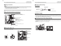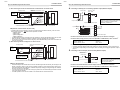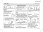
1
AIR CONDITIONER (MULTI TYPE) Installation Manual Air to Air Heat Exchanger with DX Coil Unit Model name: For commercial use Model with a humidifier MMD-VNK502HEXE MMD-VNK802HEXE MMD-VNK1002HEXE MMD-VNK1002HEXE2 Model without a humidifier MMD-VN502HEXE MMD-VN802HEXE MMD-VN1002HEXE MMD-VN1002HEXE2 Installation Manual 1 English –1– 1-EN Air to Air Heat Exchanger with DX Coil Unit Installation Manual Original instruction Please read this Installation Manual carefully before installing the Air to Air Heat Exchanger with DX Coil Unit. • This Manual describes the installation method of the Air to Air Heat Exchanger with DX Coil Unit. • For installation of the outdoor unit, follow the Installation Manual attached to the outdoor unit. ADOPTION OF NEW REFRIGERANT This Air Conditioner is a new type which adopts a new refrigerant HFC (R410A) instead of the conventional refrigerant R22 in order to prevent destruction of the ozone layer. Contents 1 Precautions for Safety . . . . . . . . . . . . . . . . . . . . . . . . . . . . . . . . . . . . . . . . . . . . . . . . . 2 2 Accessory Parts . . . . . . . . . . . . . . . . . . . . . . . . . . . . . . . . . . . . . . . . . . . . . . . . . . . . . . 4 3 Restrictions on System Construction. . . . . . . . . . . . . . . . . . . . . . . . . . . . . . . . . . . . . 5 2-EN Air to Air Heat Exchanger with DX Coil Unit Thank you for purchasing this Toshiba Air to Air Heat Exchanger with DX Coil Unit This Installation Manual describes the installation method of the Air to Air Heat Exchanger with DX Coil Unit. For installation of outdoor units, follow the Installation Manual supplied with the outdoor unit. Moreover, as this installation manual includes the important articles concerning the “Machinery” Directive (Directive 2006/42/ EC), please read through the manual and make sure you understand it. After installation, give this Installation Manual, the Owner’s Manual and the Installation Manual supplied with the outdoor unit to the customer and tell the customer to keep them safe. Prepare an exclusive power source for indoor units, independent to that for outdoor units. Y-shaped branching joints or a branching header (separately purchased) are required for connecting pipes between indoor and outdoor units. Choose either of them considering the system capacity concerning piping. For installing branching pipes, refer to the installation manual of the Y-shaped branching unit or branching header (separately purchased). Outdoor connecting branching joints are required for connecting between outdoor units. Generic Denomination: Air conditioner (Air to Air Heat Exchanger with DX Coil Unit) Definition of Qualified Installer or Qualified Service Person The Air to Air Heat Exchanger with DX Coil Unit must be installed, maintained, repaired and removed by a qualified installer or qualified service person. When any of these jobs is to be done, ask a qualified installer or qualified service person to do them for you. A qualified installer or qualified service person is an agent who has the qualifications and knowledge described in the table below. Agent Qualified installer Qualified service person • The qualified service person is a person who installs, repairs, maintains, relocates and removes the Air to Air Heat Exchanger with DX Coil Units made by Toshiba Carrier Corporation. He or she has been trained to install, repair, maintain, relocate and remove the Air to Air Heat Exchanger with DX Coil Units made by Toshiba Carrier Corporation or, alternatively, he or she has been instructed in such operations by an individual or individuals who have been trained and is thus thoroughly acquainted with the knowledge related to these operations. • The qualified service person who is allowed to do the electrical work involved in installation, repair, relocation and removal has the qualifications pertaining to this electrical work as stipulated by the local laws and regulations, and he or she is a person who has been trained in matters relating to electrical work on the Air to Air Heat Exchanger with DX Coil Units made by Toshiba Carrier Corporation or, alternatively, he or she has been instructed in such matters by an individual or individuals who have been trained and is thus thoroughly acquainted with the knowledge related to this work. • The qualified service person who is allowed to do the refrigerant handling and piping work involved in installation, repair, relocation and removal has the qualifications pertaining to this refrigerant handling and piping work as stipulated by the local laws and regulations, and he or she is a person who has been trained in matters relating to refrigerant handling and piping work on the Air to Air Heat Exchanger with DX Coil Units made by Toshiba Carrier Corporation or, alternatively, he or she has been instructed in such matters by an individual or individuals who have been trained and is thus thoroughly acquainted with the knowledge related to this work. • The qualified service person who is allowed to work at heights has been trained in matters relating to working at heights with the Air to Air Heat Exchanger with DX Coil Units made by Toshiba Carrier Corporation or, alternatively, he or she has been instructed in such matters by an individual or individuals who have been trained and is thus thoroughly acquainted with the knowledge related to this work. 5 Installation of Indoor Unit. . . . . . . . . . . . . . . . . . . . . . . . . . . . . . . . . . . . . . . . . . . . . . . 6 6 Drain Piping Work . . . . . . . . . . . . . . . . . . . . . . . . . . . . . . . . . . . . . . . . . . . . . . . . . . . . . 8 8 Installation of Ducts . . . . . . . . . . . . . . . . . . . . . . . . . . . . . . . . . . . . . . . . . . . . . . . . . . . 9 9 Refrigerant Piping and Vacuuming . . . . . . . . . . . . . . . . . . . . . . . . . . . . . . . . . . . . . . . 9 10 Electric Wiring . . . . . . . . . . . . . . . . . . . . . . . . . . . . . . . . . . . . . . . . . . . . . . . . . . . . . . . 11 11 System Configuration. . . . . . . . . . . . . . . . . . . . . . . . . . . . . . . . . . . . . . . . . . . . . . . . . 14 12 Advanced System . . . . . . . . . . . . . . . . . . . . . . . . . . . . . . . . . . . . . . . . . . . . . . . . . . . . 16 13 Advanced Control . . . . . . . . . . . . . . . . . . . . . . . . . . . . . . . . . . . . . . . . . . . . . . . . . . . . 18 14 Fan Characteristics. . . . . . . . . . . . . . . . . . . . . . . . . . . . . . . . . . . . . . . . . . . . . . . . . . . 22 15 Test Run. . . . . . . . . . . . . . . . . . . . . . . . . . . . . . . . . . . . . . . . . . . . . . . . . . . . . . . . . . . . 23 16 Maintenance . . . . . . . . . . . . . . . . . . . . . . . . . . . . . . . . . . . . . . . . . . . . . . . . . . . . . . . . 24 17 Troubleshooting . . . . . . . . . . . . . . . . . . . . . . . . . . . . . . . . . . . . . . . . . . . . . . . . . . . . . 27 Qualifications and knowledge which the agent must have • The qualified installer is a person who installs, maintains, relocates and removes the Air to Air Heat Exchanger with DX Coil Units made by Toshiba Carrier Corporation. He or she has been trained to install, maintain, relocate and remove the Air to Air Heat Exchanger with DX Coil Units made by Toshiba Carrier Corporation or, alternatively, he or she has been instructed in such operations by an individual or individuals who have been trained and is thus thoroughly acquainted with the knowledge related to these operations. • The qualified installer who is allowed to do the electrical work involved in installation, relocation and removal has the qualifications pertaining to this electrical work as stipulated by the local laws and regulations, and he or she is a person who has been trained in matters relating to electrical work on the Air to Air Heat Exchanger with DX Coil Units made by Toshiba Carrier Corporation or, alternatively, he or she has been instructed in such matters by an individual or individuals who have been trained and is thus thoroughly acquainted with the knowledge related to this work. • The qualified installer who is allowed to do the refrigerant handling and piping work involved in installation, relocation and removal has the qualifications pertaining to this refrigerant handling and piping work as stipulated by the local laws and regulations, and he or she is a person who has been trained in matters relating to refrigerant handling and piping work on the Air to Air Heat Exchanger with DX Coil Units made by Toshiba Carrier Corporation or, alternatively, he or she has been instructed in such matters by an individual or individuals who have been trained and is thus thoroughly acquainted with the knowledge related to this work. • The qualified installer who is allowed to work at heights has been trained in matters relating to working at heights with the Air to Air Heat Exchanger with DX Coil Units made by Toshiba Carrier Corporation or, alternatively, he or she has been instructed in such matters by an individual or individuals who have been trained and is thus thoroughly acquainted with the knowledge related to this work. 4 Selection of Installation Place . . . . . . . . . . . . . . . . . . . . . . . . . . . . . . . . . . . . . . . . . . . 5 7 Water Supply Piping for a Humidifier . . . . . . . . . . . . . . . . . . . . . . . . . . . . . . . . . . . . . 8 Installation Manual Definition of Protective Gear When the Air to Air Heat Exchanger with DX Coil Unit is to be transported, installed, maintained, repaired or removed, wear protective gloves and ‘safety’ work clothing. In addition to such normal protective gear, wear the protective gear described below when undertaking the special work detailed in the table below. Failure to wear the proper protective gear is dangerous because you will be more susceptible to injury, burns, electric shocks and other injuries. Installation Manual Air to Air Heat Exchanger with DX Coil Unit Work undertaken Air to Air Heat Exchanger with DX Coil Unit 1 Protective gear worn All types of work Protective gloves ‘Safety’ working clothing Electrical-related work Gloves to provide protection for electricians and from heat Work done at heights (50 cm or more) Helmets for use in industry Transportation of heavy objects Shoes with additional protective toe cap Repair of outdoor unit Gloves to provide protection for electricians and from heat WARNING ELECTRICAL SHOCK HAZARD Disconnect all remote electric power supplies before servicing. WARNING Moving parts. Do not operate unit with inspection cover removed. Stop the unit before the servicing. CAUTION High temperature parts. You might get burned when removing this cover. CAUTION Do not touch the aluminum fins of the unit. Doing so may result in injury. Precautions for Safety WARNING General • Before starting to install the Air to Air Heat Exchanger with DX Coil Unit, read carefully through the Installation Manual, and follow its instructions to install the Air to Air Heat Exchanger with DX Coil Unit. • Install the Air to Air Heat Exchanger with DX Coil Unit at least 2.5 m above the floor level since otherwise the users may injure themselves or receive electric shocks if they poke their fingers or other objects into the Air to Air Heat Exchanger with DX Coil Unit while it is running. • Before opening the electrical control cover, inspection cover or maintenance cover of the Air to Air Heat Exchanger with DX Coil Unit, set the circuit breaker to the OFF position. Failure to set the circuit breaker to the OFF position may result in electric shocks through contact with the interior parts. • Only a qualified installer (*1) or qualified service person (*1) is allowed to undertake work at heights using a stand of 50 cm or more or to remove the electrical control cover, inspection cover or maintenance cover of the Air to Air Heat Exchanger with DX Coil Unit to undertake work. • When working at heights, use a ladder which complies with the ISO 14122 standard, and follow the procedure in the ladder’s instructions. Also wear a helmet for use in industry as protective gear to undertake the work. • Only a qualified installer (*1) or qualified service person (*1) is allowed to carry out the electrical work of Air to Air Heat Exchanger with DX Coil Unit. • Under no circumstances must this work be done by an unqualified individual since failure to carry out the work properly may result in electric shocks and/or electrical leaks. • Electrical wiring work shall be conducted according to law and regulation in the community and Installation manual. Failure to do so may result in electrocution/short circuit. • When repairing the electrical parts or undertaking other electrical jobs, wear gloves to provide protection for electricians and from heat. Failure to wear this protective gear may result in burn. • Before carrying out the installation, maintenance, repair or removal work be sure to set the circuit breaker for the Air to Air Heat Exchamger Unit to the OFF position. Otherwise, electric shocks may result. • Place a “Work in progress” sign near the circuit breaker while the installation, maintenance, repair or removal work is being carried out. There is a danger of electric shocks if the circuit breaker is set to ON by mistake. • When cleaning the filter, heat exchange element or humidifier of the Air to Air Heat Exchanger with DX Coil Unit, set the circuit breaker to OFF without fail, and place a “Work in progress” sign near the circuit breaker before proceeding with the work. • Before opening the electrical control cover, inspection cover and maintenance cover of the Air to Air Heat Exchanger with DX Coil Unit, set the circuit breaker to the OFF position. • Failure to set the circuit breaker to the OFF position may result in electric shocks through contact with the interior parts. Only a qualified installer (*1) or qualified service person (*1) is allowed to remove the electrical control cover, inspection cover and maintenance cover of the Air to Air Heat Exchanger with DX Coil Unit and do the work required. • Only a qualified installer (*1) or qualified service person (*1) is allowed to undertake work at heights using a stand of 50 cm or more or to remove the electrical control box cover, inspection cover or maintenance cover of the Air to Air Heat Exchanger with DX Coil Unit to undertake work. • When working at heights, use a ladder which complies with the ISO 14122 standard, and follow the procedure in the ladder’s instructions. Also wear a helmet for use in industry as protective gear to undertake the work. • When cleaning the filter, heat exchange element or humidifier of the Air to Air Heat Exchanger with DX Coil Unit, set the circuit breaker to OFF without fail, and place a “Work in progress” sign near the circuit breaker before proceeding with the work. • Do not install the Air to Air Heat Exchanger with DX Coil Unit in a location that may be subject to a risk of expire to a combustible gas. If a combustible gas leaks and becomes concentrated around the unit, a fire may occur. • Do not place any combustion appliance in a place where it is directly exposed to the wind of Air to Air Heat Exchange with DX Coil unit, otherwise it may cause imperfect combustion. • If refrigerant gas has leaked during the installation work, ventilate the room immediately. If the leaked refrigerant gas comes in contact with fire, noxious gas may be generated. • After the installation or servicing work, check the refrigerant gas does not leak. • If refrigerant gas leaks in the room, poisonous gas generates when gas touches to fire such as fan heater, stove or cooking stove though the refrigerant gas itself is innocuous. • Inspect the Air to Air Heat Exchanger Unit with DX Coil for any falling hazard of the unit before maintenance or repair. • Do not modify the products. Do not also disassemble or modify the parts. It may cause a fire, electric or injury. Warning Indications on the Air Conditioner Unit Warning indication Installation Manual Description WARNING ELECTRICAL SHOCK HAZARD Disconnect all remote electric power supplies before servicing. WARNING Moving parts. Do not operate unit with inspection cover removed. Stop the unit before the servicing. CAUTION High temperature parts. You might get burned when removing this cover. CAUTION Do not touch the aluminium fins of the unit. Doing so may result in injury. Selection of installation location • Install the Air to Air Heat Exchanger Unit securely in a location where the base can sustain the weight adequately. If the strength is insufficient, the unit may fall down resulting in human injury. • Do not install the unit in places 1) with high temperature 2) where the unit is subject to direct fire 3) where much oil smoke is generated. Otherwise, a fire may result. 3-EN –2– EN 4-EN –3– 5-EN Air to Air Heat Exchanger with DX Coil Unit Installation Manual • Do not install the unit in a machinery factory or a chemical plant, where a toxic gas containing acid, alkali, an organic solvent, or paint, or a gas containing a corrosive substance is generated. Gas poisoning or a fire may result. • Do not install in a location where flammable gas may leaks are possible. If the gas leak and accumulate around the unit, it may ignite and cause a fire. • Install the unit so that the air outlet is located at least 1.5m from the nearest fire alarm. Otherwise, when a fire occurs, the fire alarm may be late to detect it, or may not detect it at all. Installation • Transport it by the truck or the forklift. Transport it by six people or more when the person transports it temporarily. The waist etc. might be hurt when not following it. • When transporting the Air to Air Heat Exchanger with DX Coil Unit, wear shoes with additional protective toe caps, protective gloves, and other protective clothing. • When transporting the Air to Air Heat Exchanger with DX Coil Unit, do not take hold of the bands around the packing carton. You may injure yourself if the bands should break. • When the Air to Air Heat Exchanger with DX Coil Unit is to be suspended, the designated hanging bolts (M12) and nuts (M12) must be used • Install the Air to Air Heat Exchanger with DX Coil Unit at enough strong place to withstand the weight of the unit. If the strength is not enough, the unit may fall down resulting in injury • Follow the instructions in the Installation Manual to install the Air to Air Heat Exchanger with DX Coil Unit. Failure to follow these instructions may cause the product to fall down or topple over or give rise to noise, vibration, water leakage, etc. • Wear protective gloves and safety work clothing during installation, servicing and removal. • Do not touch the aluminum fin of the Air to Air Heat Exchanger with DX Coil Unit or outdoor unit. You may injure yourself if you do so. If the fin must be touched for some reason, first put on protective gloves and safety work clothing, and then proceed. • Tighten the flare nut with a torque wrench in the specified manner. Excessive tighten of the flare nut may cause a crack in the flare nut after a long period, which may result in refrigerant leakage. • When working at heights, put a sign in place so that no-one will approach the work location, before proceeding with the work. Parts and other objects may fall from above, possibly injuring a person below. • Before starting to install the Air to Air Heat Exchanger with DX Coil Unit, read carefully through the Installation Manual, and follow its instructions to install the Air to Air Heat Exchanger with DX Coil Unit. • Only a qualified installer (*1) or qualified service person (*1) is allowed to install the Air to Air Heat Exchanger with DX Coil Unit. If the Air to Air Heat Exchanger with DX Coil Unit is installed by an unqualified individual, a fire, electric shocks, injury, water leakage, noise and/or vibration may result. • Upon completion of the installation work, check for the insulation resistance. Then conduct a test run to check that the Air to Air Heat Exchanger with DX Coil Unit is operating properly. • After the work has finished, be sure to use an insulation tester set (500V Megger) to check the resistance is 1MΩ or more between the charge section and the non-charge metal section (Earth section). If the resistance value is low, a disaster such as a leak or electric shock is caused at user's side. • Before starting to install the Air to Air Heat Exchanger with DX Coil Unit, read carefully through the Installation Manual, and follow its instructions to install the Air to Air Heat Exchanger with DX Coil Unit. • Follow the instructions in the Installation Manual to install the Air to Air Heat Exchanger with DX Coil Unit. Failure to follow these instructions may cause the product to fall down or topple over or give rise to noise, vibration, water leakage, etc. • Before operating the Air to Air Heat Exchanger with DX Coil Unit after having completed the work, check that the electrical control cover, inspection cover and maintenance cover are closed, and set the circuit breaker to the ON position. You may receive an electric shock if the power is turned on without first conducting these checks. • Install the unit in the prescribed manner for protection against strong wind and earthquake. Incorrect installation may result in the unit falling down, or other accidents. • Attach an anti bird net or the like to the outside air intake. Remove any foreign object such as a nest; otherwise, an oxygen shortage may occur in the room. • Leave ample space between the outside air intake and the outlet for combustion gas. Otherwise, an oxygen shortage may occur in the room. • When metallic ducts pass through a wooden construction covered with a metal lath, wire lath, or metal plate, install the ducts so that they are not electrically in contact with the metal parts of wooden construction. If a short circuit occurs, a fire may result. • Use the supplied or specified parts for installation. Otherwise, the unit falling down, water leakage, an electric shock, or a fire may result. • Perform anti-freezing work if the installation place is subject to freezing. Otherwise, the solenoid valve or pipes are damaged and water leakage may result. • Do not install the unit in a place where the outside temperature (especially around the unit or the air grill) falls below 0°C. Otherwise, water in the pipes, in the humidifying element, or in the solenoid valve freezes and a breakdown or water leakage may result. • If the ducts pass through a fire protection zone, use a noncombustible duct and install a fire damper. The flame may spread when a fire occurs. 6-EN Air to Air Heat Exchanger with DX Coil Unit Installation Manual • Install the ducts to the outside inclined downward so that rainwater does not enter the ducts. Otherwise, water will enter the room and household goods will become wet. • Insulate the ducts from heat using a heat insulator to prevent condensation. Otherwise, furniture may be damaged. • If it is hot and humid in the ceiling cavity, install a ventilator. Otherwise, a fire or a short circuit may result. • Install drain pipes to drain water securely referring to the Installation Manual. In addition, insulate the pipes from heat to prevent condensation. Inappropriate piping results in water leaking into the room and the ceiling, floor or furniture may be damaged. Explanations given to user • After the installation work, Follow the Owner's manual to explain to the customer how to use and maintain the unit. • Do not place any combustion appliance in a place where it is directly exposed to the wind of Air to Air Heat Exchanger with DX Coil Unit, otherwise it may cause imperfect combustion. • For safety, turn off the unit if you do not use it for a long time. A fire or an electric shock may result due to insulation degradation. Relocation • Only a qualified installer (*1) or qualified service person (*1) is allowed to relocate the Air to Air Heat Exchanger with DX Coil Unit. It is dangerous for the Air to Air Heat Exchanger with DX Coil Unit to be relocated by an unqualified individual since a fire, electric shocks, injury, water leakage, noise and/or vibration may result. • For the refrigerant recovery work (collection of refrigerant from the pipe to the compressor), stop the compressor before disconnecting the refrigerant pipe. If the refrigerant pipe is disconnected while the compressor is working with the valve open, the compressor sucks air and the refrigeration cycle is overpressurized, which may cause a burst or injury. Refrigerant piping • Install the refrigerant pipe securely during the installation work before operating the compressor. If the compressor is operated with the valve open and without refrigerant pipe, the compressor sucks air and the refrigeration cycles is over pressurized, which may cause a injury. • Do not use any refrigerant different from the one specified for complement or replacement. Otherwise, abnormally high pressure may be generated in the refrigeration cycle, which may result in a failure or explosion of the product or an injury to your body. • Only a qualified installer(*1) or qualified service person(*1) is allowed to do installation work. If installation is carried out by an unqualified individual, a fire, electric shocks, injury, water leakage, noise and/or vibration may result. Electrical wiring • Use wiring that meets the specifications in the Installation Manual and the stipulations in the local regulations and laws. Use of wiring which does not meet the specifications may give rise to electric shocks, electrical leakage, smoking and/or a fire. • Be sure to connect earth wire. (Grounding work) • Incomplete earthing cause an electric shock. • Do not connect earth wires to gas pipes, water pipes, lightning rods or earth wires for telephone wires • After completing the repair or relocation work, check that the earth wires are connected properly. • Install a circuit breaker that meets the specifications in the installation manual and the stipulations in the local regulations and laws. • Install the circuit breaker where it can be easily accessed by the agent. • When installing the circuit breaker outdoors, install one which is designed to be used outdoors. • When you have noticed that some kind of trouble (such as when an error display has appeared, there is a smell of burning, abnormal sounds are heard, the Air to Air Heat Exchanger with DX Coil Unit falls to cool or heat, or water is leaking) has occurred in the Air to Air Heat Exchanger with DX Coil Unit, do not touch the Air to Air Heat Exchanger with DX Coil Unit yourself but set the circuit breaker to the OFF position, and contact a qualified service person (*1). Take steps to ensure that the power will not be turned on (by marking “out of service” near the circuit breaker, for instance) until qualified service person arrives. Continuing to use the Air to Air Heat Exchanger with DX Coil Unit in the trouble status may cause mechanical problems to escalate or result in electric shocks, etc. • Upon completion of the installation work, tell the user where the circuit breaker is located. If the user does not know where the circuit breaker is, he or she will not be able to turn it off in the event that trouble has occurred in the Air to Air Heat Exchanger with DX Coil Unit. • Use the rated voltage. Otherwise, a fire or an electric shock may result. • Connect power cords or connection wires securely so that the power supply cover is attached properly. Otherwise, a fire or an electric shock may result. • Do not install the unit or the switch in a humid place such as a bathroom. Otherwise, a fire or an electric shock may result. (*1) Refer to the “Definition of Qualified Installer or Qualified Service Person.” Air to Air Heat Exchanger with DX Coil Unit Installation Manual Installation Manual Air to Air Heat Exchanger with DX Coil Unit 2 CAUTION New Refrigerant Air to Air Heat Exchanger with DX Coil Unit Installation • THIS Air to Air Heat Exchanger with DX Coil Unit ADOPTS THE NEW HFC REFRIGERANT (R410A) WHICH DOES NOT DESTROY OZONE LAYER. • The characteristics of R410A refrigerant are; easy to absorb water, oxidizing membrane or oil, and its pressure is approx. 1.6 times higher than that of refrigerant R22. Accompanied with the new refrigerant, refrigerating oil has also been changed. Therefore, during installation work, be sure that water, dust, former refrigerant, or refrigerating oil does not enter the refrigerating cycle. • To prevent charging an incorrect refrigerant and refrigerating oil, the sizes of connecting sections of charging port of the main unit and installation tools are changed from those for the conventional refrigerant. • Accordingly the exclusive tools are required for the new refrigerant (R410A). • For connecting pipes, use new and clean piping designed for R410A, and please care so that water or dust does not enter. Accessory Parts Name To Disconnect the Appliance from Main Power Supply. • Means for disconnection having a contact separation in all poles at least 3 mm must be incorporated in the fixed wiring in accordance with the wiring rules. Quantity Shape Usage Installation manual 1 This manual CD-ROM (Owner’s manual, Installation manual) 1 — (For other languages that do not appear in this manual, please refer to the enclosed CD-ROM.) Owner’s manual 1 — (Be sure to hand it to the customers.) Insulation 1 For strainers Insulation 4 For insulation of hanging brackets Insulation 1 For water supply pipes Duct connectors 4 Connector with ducts Screws 24 For duct connectors (Be sure to hand it to the customers.) The installation fuse (All Types Can Be Used) must be used for the power supply line of this Air to Air Heat Exchanger with DX Coil Unit. Separately sold parts The remote controller (NRC-01HE) is sold separately. For the installation of these products, follow the installation manual supplied with it. EN 7-EN –4– 8-EN –5– 9-EN Air to Air Heat Exchanger with DX Coil Unit 3 Installation Manual Restrictions on System Construction Installation Manual Air to Air Heat Exchanger with DX Coil Unit 4 Selection of Installation Place CAUTION System combinations available The Air to Air Heat Exchanger with DX Coil Unit can be connected to a Super Module Multi system -i. Range of combination 1. The Air to Air Heat Exchanger with DX Coil Unit can be connected with either one of the following multi systems: • System with Air to Air Heat Exchanger with DX Coil Unit and air conditioner indoor units • Air to Air Heat Exchanger with DX Coil Unit system 2. The overall capacity (HP) of air conditioner indoor units and Air to Air Heat Exchanger with DX Coil Unit should be 80 to 135% of that of outdoor units. System with Air to Air Heat Exchanger with DX Coil Unit and air conditioner indoor units Air conditioner indoor units 10-EN Air to Air Heat Exchanger with DX Coil Unit Air to Air Heat Exchanger with DX Coil Unit system Air to Air Heat Exchanger with DX Coil Unit The Air to Air Heat Exchanger with DX Coil Unit and the concealed duct type fresh air intake unit cannot be used together in the same system. • Do not install the Air to Air Heat Exchanger with DX Coil Unit in a location subject to a risk of exposure to a combustible gas. If a combustible gas leaks and stays around the unit, a fire may occur. • Install the unit so that the air outlet is located at least 1.5m from the nearest fire alarm. Otherwise, when a fire occurs, the fire alarm may be late to detect it, or may not detect it at all. • • • • more, or when the draining pipe is clogged, water droplets may fall from the unit. Place near a door or window exposed to humid outside air (Dew dropping may form.). Place where special spray is used frequently. Places such as outdoors or under the eaves (where rain may fall directly on the unit). Do not use the unit in chemical plants with a cooling system which uses liquid carbon dioxide, etc. Installation space Install the indoor unit in a place where cool/warm air circulates evenly. Avoid installing in the following places. • Places where the outside temperature falls below 5°C. (If the temperature around the unit falls below 5°C, water in humidifier freezes and the water will leak. • Places where air pipes are installed in the ceiling cavity. • Place exposed to air with high salt content (seaside area) • Place exposed to large quantities of sulfide gas (hot spring). (Should the unit be used in these places, special protective measures are needed.) • A restaurant kitchen where a lot of oil is used or place near machines in a factory (Oil adhering to the heat exchanger and resin part (turbo fan) in the indoor unit may reduce the performance, generate mist or dew drop, or deform or damage resin parts.) • Places where obstacles disturbing the air current such as a ventilation hole or lighting apparatus are near the unit. (The performance of the unit may be deteriorated or the unit may not work due to disturbance of the air current.) • Do not use the air conditioner for special purposes such as preserving food, precision instruments, or art objects, or where breeding animals or growing plants are kept. (This may degrade the quality of preserved materials.) • Place where any of high-frequency appliances (including inverter devices, private power generators, medical equipment, and communication equipment) and inverter-type fluorescent light is installed. (A malfunction of the air conditioner, abnormal control, or problems due to noise to such appliances/ equipment may occur.) • Places where there is something that must not become wet. When the humidity reaches 80% or Leave ample space for installation or servicing. 200mm or more 200mm 600mm 1000mm or more Inspection opening 600mm ¯ 600mm REQUIREMENT • Before installing indoor units, attach any accessories (drain-up kit, etc.: separately purchased) to them. In addition, make inspection opening on both sides of each unit. • The size of inspection opening should be 600mm × 600mm. Installation Manual 5 Installation in high-humidity places • Install the air conditioner at enough strong place to withstand the weight of the unit. If the strength is not enough, the unit may fall down resulting in injury. • To provide against strong wind or an earthquake, install the unit appropriately. Inappropriate installation may result in the unit falling down and causing an accident. • Use a forklift to carry the unit. As it is packed in a cardboard box, do not drag or push it. • Suction duct length must be longer than 850 mm. • Helmet must be worn to protect your head from falling objects. Especially, when you work under an inspection opening, helmet must be worn to protect your head from falling objects from the opening. External dimensions A EA (Exhaust air) RA (Return air) 400 400 ØH E D D B K 800 SA (Supply air) OA (Outdoor air) E Inspection cover 550 430 C E Dry-bulb temperature (°C) Electrical control cover • Do not install the unit near a water heater. 11-EN G J E B' Strictly comply with the following rules to prevent damage of the indoor units and human injury. • Do not put a heavy article on the indoor unit. (Even units are packaged) • Carry in the indoor unit as it is packaged if possible. If carrying in the indoor unit unpacked by necessity, be sure to use buffering cloth, etc. to not damage the unit. • To move the indoor unit, hold the hooking metals (4 positions) only. Do not apply force to the other parts (refrigerant pipe, drain pan, foamed parts, or Box for supplied resin parts, etc.). accessories Before you handle hanging brackets, put on thick gloves for protection. • Supplied accessories are placed near the electrical control box. Do not dispose of the accessories with the packaging. (See the figure on the right.) • When a vibration-proof hanging bracket is attached to a hanging bolt, confirm that the unit does not vibrate more through using the vibration-proof hanging bracket. F C' B NOTE Absolute humidity (kg/kg’) Sa tur ati on Cu rve • Be careful of dewing and frosting. • In cold regions, the surface of the unit or the duct connector may be affected by condensation or frosting depending on the outdoor air conditions or temperature/humidity of the ceiling cavity even though the conditions for use are observed. In this case, add a heat insulator. • Water droplets may fall if the unit is operated in wet conditions. In particular, high humidity may occur even during non-rainy season if the unit is installed in the following locations: 1. Ceiling of a tile roof 2. Ceiling of a slate roof In this case, attach thermal insulators (glass wool, etc.) on the unit’s surface. Take care so that you can remove the side board (service panel) easily even when insulators are attached. Also insulate the duct and its connectors sufficiently. • Do not install the unit in a place where there is something that must not become wet. Depending on the temperature or humidity of outdoor air and the installation place, water droplets may fall from the unit. • As shown in the figure to the below, suppose a high temp absorbing air condition A and a low temp absorbing air condition B are plotted on the air line figure, then a high temp air A is heatexchanged by the unit and goes out of the saturation curve as shown by Point C. In this case, the unit will be dewed or frosted. To avoid this, heating a low temp air B up to B’ is required so as to get C’ below the saturation curve, before using the unit. C Installation of Indoor Unit WARNING • Do not use the unit in a kitchen or bathroom. If the unit is used in a place where much oil smoke is generated or a place with high humidity, the filter or the heat exchanging element will become clogged and the unit will not work. A Installation Manual Air to Air Heat Exchanger with DX Coil Unit ØI Air to Air Heat Exchanger with DX Coil Unit –6– EN Maintenance cover 12-EN –7– 13-EN Installation Manual Air to Air Heat Exchanger with DX Coil Unit Unit: mm Model No. A B C D E F MMD-VNK502HEXE, VN502HEXE 1,690 1140 1140 250 175 350 MMD-VNK802HEXE, VN802HEXE 1,739 1189 1189 275 200 400 MMD-VNK1002HEXE, VN1002HEXE 1,739 1189 1189 275 200 400 MMD-VNK1002HEXE2, VN1002HEXE2 1,739 1189 1189 275 200 400 14-EN Installation Manual Air to Air Heat Exchanger with DX Coil Unit Installing the indoor unit Attaching the duct connector Attach 4 duct connectors to the unit using the six screws supplied for each connector. Duct connector Screws Diameter of refrigerant piping at the gas side (L) Diameter of refrigerant piping at the liquid side (M) Ø200 Ø9.5 Ø6.4 Ø250 Ø12.7 Ø6.4 1246 Ø250 Ø12.7 Ø6.4 1246 Ø250 Ø12.7 Ø6.4 G H I J K Duct diameter MMD-VNK502HEXE, VN502HEXE 173 Ø195 Ø212 1601 1197 MMD-VNK802HEXE, VN802HEXE 198 Ø245 Ø262 1650 1246 MMD-VNK1002HEXE, VN1002HEXE 198 Ø245 Ø262 1650 MMD-VNK1002HEXE2, VN1002HEXE2 198 Ø245 Ø262 1650 Model No. Center of gravity Attaching the washers and nuts 1 2 Procure the hanging bolts, nuts, and washers locally. Attach the washers and nuts to the hanging bolt (M12) as shown in the figure on the right. X Hanging bolt (M12) Nut Washer Y Nut Z Fixing the unit 1 2 Fit the hanging bracket on the hanging bolt, then adjust the position of the unit so that it is level. Tighten the bolts securely using a double nut to prevent the bolts from becoming loose. • If the bolts are not tightened securely, the unit will vibrate and an accident may occur. • Tighten the bolts so that they can bear the weight of the unit. 3 Confirm that the unit is installed level. • Confirm that the unit is installed level or is inclined within 1°(downward) against the drain outlet using a spirit level. • Do not set the unit inclined (upward) against the drain outlet; otherwise, water will leak from the unit. Hanging bolt (Ø12) Model No. Nut X Y Z Weight MMD-VNK502HEXE 902 643 174 91 Washer MMD-VNK802HEXE 901 667 199 111 MMD-VNK1002HEXE 900 667 199 112 MMD-VNK1002HEXE2 894 666 199 114 Washer Nut Hanging bracket MMD-VN502HEXE 870 642 174 84 MMD-VN802HEXE 856 663 198 100 MMD-VN1002HEXE 853 663 198 101 MMD-VN1002HEXE2 858 662 198 103 Within 1° Within 1° Hanging bolt (Ø12) Vibration-proof hanging bracket CAUTION To preventing vibration, use vibration proof hanging brackets (procured locally). Vibrationproof hanging bracket Installation Manual Air to Air Heat Exchanger with DX Coil Unit 6 7 Drain Piping Work Connecting drain pipe CAUTION Install drain pipes to drain water securely referring to the Installation Manual. In addition, insulate the pipes from heat to prevent condensation. (Inappropriate piping results in water leaking into the room and furniture may be damaged.) REQUIREMENT • Install drain pipes to prevent water from leaking. • Set the drain pipe with downward slope (1/100 or more), and do not make swelling or trap on the piping. It may cause an abnormal sound. • For length of the traversing drain pipe, restrict to 20 m or less. In case of a long pipe, provide support brackets with interval of 1.5 - 2 m in order to prevent waving. • Set the collective piping as shown in the below figure. • Do not apply force to the connecting part of the drain pipe. • Perform heat insulation of the drain pipes of the indoor unit. • Perform heat insulation of the connecting part with the indoor unit. An incomplete heat insulation causes dew dropping. • If the installation place is subject to freezing, perform anti-freezing work. Installation Manual Air to Air Heat Exchanger with DX Coil Unit Water Supply Piping for a Humidifier CAUTION Install the water supply pipes after washing the inside of them with water. Install a drain valve on the water supply pipe, then drain the water until the drained water runs clear. Do not to allow cutting fluid or detergent to enter the pipes. The water quality of the humidifiers supply water should meet public waterworks standards, and have a hardness less than 100mg/ℓ. If the supply water does not meet these standards, use a deionizer. NOTE • Connect hard vinyl chloride pipes securely using an adhesive for vinyl chloride to avoid water leakage. • It takes some time until the adhesive is dried and hardened (refer to the manual of the adhesive). Do not apply stress to the joint with the drain pipe during this time period. NOTE • If the installation place is subject to freezing, perform anti-freezing work. • Do not connect the water supply pipe directly to the public water pipe. Use a cistern tank (procured locally). • Use water which meets the following conditions: Drain-up • Water pressure: 2×10⁴Pa to 49×104Pa • Water temperature: 5°C to 40°C For the installation instruction of a drain-pump kit (sold separately), refer to the Installation Manual supplied with the drain-pump kit. • Attach a service valve or drain valve (procured locally) near the water intake. While the humidifier is not in operation, the water inside the pipes and cistern tank does not flow and becomes stagnant. If the stagnant water is used for water supply in the initial stages of using the humidifier (heater), a smell may come out or bacteria may multiply. If you do not use the humidifier for a long time, drain off water from the pipes and from the cistern tank. Before the season for using the humidifier (heater) arrives, open the drain/water supply valves to exchange the water inside the pipes. • Close the water supply valve when the season for using the humidifier (heater) has passed. • Prevent corrosive gas, salt, or oil mist from entering the air. • Clean the strainer for water supply when the season for using the humidifier (heater) arrives. • Fix the water supply pipes so that excessive force is not applied to them. • Arrange the pipes so that they do not obstruct opening the maintenance cover for the heat transfer element/ humidification element or removing the humidification element. • Do not allow cutting fluid from being mixed with the supplying water as it causes the humidifying unit or drain pan to deteriorate. If cutting fluid sticks to it, wash it immediately in a sufficient amount of water. • Use 2 wrenches, to connect a pipe to a single union pipe joint or to remove it from the single union pipe joint. • Drain off water from the cistern tank when the humidifier is not used. Check the draining In the test run, check that water drain is properly performed and water does not leak from the connecting part of the pipes. REQUIREMENT • Check draining also when installed in heating period. • Using a pitcher or hose, pour water (1500 - 2000 cc) into the discharge port before installation of the maintenance cover. Heat insulator (for the water supply pipe) Water inlet connecting part size R1/2 Heat insulator (for the strainer) Unit Piping/Heat insulating material maintenance cover Procure the following materials for piping and heat insulating locally. Piping Hard vinyl chloride pipe VP25 (Outer dia. : Ø32 mm) Heat insulator Foam polyethylene: Thickness 10 mm or more Service valve Cap Drain valve EN 15-EN –8– 16-EN –9– 17-EN Installation Manual Air to Air Heat Exchanger with DX Coil Unit 8 18-EN 9 Installation of Ducts CAUTION • Ventilate the room if a refrigerant gas is leaking during the installation work. If the leaking refrigerant gas comes in contact with fire, a toxic gas is generated. • After installation, confirm that no refrigerant gas is leaking. If the leaking refrigerant gas comes in contact with fire from a fan heater, a stove, or a gas range, a toxic gas is generated. Installing ducts 2 3 4 NOTE Insert the duct into the duct connector, then fix the duct using aluminum tape to prevent air from leaking. When the refrigerant pipe is long, provide support brackets at intervals of 2.5 - 3 m to clamp the refrigerant pipe. Otherwise, abnormal sound may be generated. Use the flare nut attached with the indoor unit or R410A flare nut. Hang the duct from the ceiling so that excessive force is not applied to the unit. Leave sufficient space between the room air outlet and the room air intake. Install 2 ducts to the outside inclined downward between 1/100 and 1/50 so that water does not enter the ducts. Heat insulator Aluminium tape Heat insulator (Insulates the adapter and the aluminium tape) Outside air intake duct, Air outlet duct Duct Duct connector 5 Refrigerant Piping and Vacuuming WARNING Insulate the ducts to prevent condensation. Inappropriate installation results in water leaking into the room and furniture may be damaged. Suction duct length must be longer than 850 mm. 1 Installation Manual Air to Air Heat Exchanger with DX Coil Unit Unit Slope (1/100 to 1/50) Aluminium tape Permissible Piping Length and Height Difference They vary depending on the outdoor unit. For details, refer to the Installation Manual attached to the outdoor unit. About the pipe material and size Pipe material Aluminium tape Insulate 2 ducts to the outside and the SA (supply air) using a heat insulator to prevent condensation. Model name MMD- VNK502HEXE VN502HEXE VNK802HEXE VN802HEXE VNK1002HEXE(2) VN1002HEXE(2) Pipe size (mm) Gas side Ø9.5 Ø12.7 Ø12.7 Liquid side Ø6.4 Ø6.4 Ø6.4 (Material of insulator: glass wool, 25mm thick) NOTE Refrigerant piping at the liquid/gas side • Refrain from the following duct installation works. 1) Excessive bending 2) Multi-times bending Seamless phosphorous-deoxidized copper pipe 3) Making the connecting duct smaller 4) Bending near the exhaust air duct Flaring 1 Cut the pipe with a pipe cutter. Remove burrs completely. Remaining burrs may cause gas leakage. 2 Insert a flare nut into the pipe, and flare the pipe. As the flaring sizes of R410A differ from those of refrigerant R22, the flare tools newly manufactured for R410A are recommended. However, the conventional tools can be used by adjusting projection margin of the copper pipe. Projection margin in flaring: B (Unit: mm) Rigid (Clutch type) Outer dia. of copper pipe 6.4, 9.5 12.7 R410A tool used Conventional tool used 0 to 0.5 1.0 to 1.5 B • When metallic ducts pass through a wooden construction covered with a metal lath, wire lath, or metal plate, install the ducts so that they are not electrically in contact with the metal parts of wooden construction. • Keep the temperature in the ceiling cavity at 5°C or more; otherwise, freezing and water leakage may occur due to the built-in humidifier. • Even while the unit is not in operation, outside air may enter the room due to a pressure difference between the outside air and inside air, or outside wind. Using an electric damper is recommended. • Install a ventilator in the ceiling cavity when it is hot and the humidity is high. • When the outdoor hood for the air intake is located near a window and small insects gather around the light, they may get through the pipes and enter the room. Before installation, consider countermeasures such as setting up a filter box (Locally procured). • Arrange the pipes so that supply air and exhaust air are not mixed. • When a vent cap or a round hood for an outdoor hood is used, do not attach the hood to a place where rain may fall directly. In this case, using a rectangle hood is recommended. • Stuff the cracks in the pipe penetration part with a noncombustible material such as mortar. Installation Manual Air to Air Heat Exchanger with DX Coil Unit Air to Air Heat Exchanger with DX Coil Unit Heat insulation Flaring dia. meter size: A (Unit: mm) A +0 –0.4 Outer dia. of copper pipe R410A 6.4 9.1 9.5 13.2 12.7 16.6 Installation Manual * In case of flaring for R410A with the conventional flare tool, pull it out approx. 0.5 mm more than that for R22 to adjust to the specified flare size. The copper pipe gauge is useful for adjusting projection margin size. Apply heat insulation for the pipes separately at liquid side and gas side. • For the heat insulation to the pipes at gas side, be sure to use the material with heat-resisting temperature 248 °F (120 °C) or higher. • Using the attached heat insulation material, apply the thermal insulation to the pipe connecting section of the indoor unit securely without gap. A REQUIREMENT • The pressure of gas in the unit is the same as the atmospheric pressure. Therefore, no air leaking sound comes out when the flare nut is loosened. This is not anything unusual. • Use 2 wrenches to perform piping of indoor units. • Apply the heat insulation to the pipe connecting section of the indoor unit securely up to the root without exposure of the pipe. (The pipe exposed to the outside causes water leak.) • Wrap heat insulator with its slits facing up (ceiling side). Wrap the pipe with the attached heat insulator without any gap between the indoor unit. Indoor unit The seam must be faced upward (ceiling side). Using 2 wrenches • Refer to the table below for tightening torque. Outer diameter of connecting pipe (mm) Tightening torque (N•m) Ø6.4 14 to 18 (1.4 to 1.8kgf•m) Ø9.5 33 to 42 (3.3 to 4.2kgf•m) Ø12.7 50 to 62 (5.0 to 6.2kgf•m) Heat insulation pipe (Accessory) • Tightening torque of flare pipe connections Pressure of R410A is higher than that of R22. (Approx. 1.6 times) Therefore, using a torque wrench, tighten the flare pipe connecting sections which connect the indoor and outdoor units of the specified tightening torque. Incorrect connections may cause not only a gas leak, but also a trouble of the refrigeration cycle. Flare nut Union Heat insulator of the pipe REQUIREMENT Tightening with an excessive torque may crack the nut depending on installation conditions. Tighten the nut within the specified tightening torque. Leak check test and vacuuming Refer to the Installation Manual of the outdoor unit for leak check test, vacuuming, adding a refrigerant, or checking gas leakage. REQUIREMENT Do not turn on the indoor unit before leak check test and vacuuming are finished; otherwise, the electric expansion valve is closed fully and vacuuming from the liquid or gas side is not performed properly. If the indoor unit should be turned on, perform vacuuming from both the liquid side and the gas side. Opening the valve fully Open the valves of the designated outdoor unit fully. EN 19-EN – 10 – 20-EN – 11 – 21-EN Installation Manual Air to Air Heat Exchanger with DX Coil Unit 22-EN 10 Electric Wiring Item Model name MMD- WARNING • Use predefined wires and connect them certainly. Keep the connecting terminals free from external force. Improper wire connection or clamping may result in exotherm, fire or malfunction. • Connect earth wire. (grounding work) Incomplete grounding cause an electric shock. Do not connect ground wires to gas pipes, water pipes, lightning rods or ground wires for telephone wires. • The electric work must satisfy all local, national and international regulations. Use an exclusive power supply circuit for the unit at the rated voltage. Capacity shortage of power circuit or incomplete installation may cause an electric shock or a fire. Installation Manual Air to Air Heat Exchanger with DX Coil Unit Air to Air Heat Exchanger with DX Coil Unit VNK502HEXE VN502HEXE VNK802HEXE VN802HEXE VNK1002HEXE VN1002HEXE Communication line Indoor/Outdoor inter-unit wiring (*2) (2 cables) Central control line wiring (*3) (2 cables) (Up to 1000m) 2-core, non-polarity shield wire: 1.25 mm2 (Up to 2000m) 2-core, non-polarity shield wire: 2.00 mm2 Remote controller wiring (*4) 2-core, non-polarity: 0.5 to 2.0 mm2 VNK1002HEXE2 VN1002HEXE2 (*2) (*3) • 2-core with non-polarity wires are used for the Indoor/ Outdoor inter-unit wiring and Central controller wiring. • To prevent noise trouble, use 2-core shield wire. • The length of the communication line means the total length of the inter-unit wire length between indoor and outdoor units added with the central control system wire length. CAUTION (*4) • 2-core with non-polarity wire is used for wiring of the remote controller wiring and group remote controllers wiring. Be sure to install an earth leakage breaker. If an earth leakage breaker is not installed, an electric shock may be caused. 2-core, non-polarity: 0.5mm2 to 2.0mm2 Remote controller wiring, remote controller inter-unit wiring REQUIREMENT • Perform electrical wiring according to local regulations of each region. • Perform electrical wiring of the outdoor unit according to the Installation Manual of the outdoor unit. • Do not connect 220–240V power to the communication terminal blocks ( U1 , U2 , A , B ) for control wiring. (Otherwise, the system will fail.) • Perform electrical wiring so that wires do not come in contact with hot parts of the pipes; otherwise, heat from the pipes melts the covering of wires and an accident may result. • After connecting wires to the terminal blocks, provide a trap and fix wires with the cord clamp. • Arrange the transition wiring and the refrigerant piping so that they are in the same group. • Do not turn on the indoor unit before vacuuming of refrigerant piping is finished. Total wire length of remote controller wiring and remote controller inter-unit wiring = L + L1 + L2 + ··· Ln Wiring and remote control wire should be locally procured. See the table below for the power specifications. If the capacity is too small, the unit will suffer from overheating or burnout. Refer to the Installation Manual of the outdoor unit for the power capacity or electric wire specifications of the outdoor unit. Item Power supply for Air to Air Heat Exchanger with DX Coil Unit (*1) Model name MMD- Air to Air Heat Exchanger with DX Coil Unit Power supply VNK502HEXE VN502HEXE VNK802HEXE VN802HEXE I-phase 50Hz 220-240V I-phase 60Hz 220V VNK1002HEXE VN1002HEXE I-phase 50Hz 220-240V VNK1002HEXE2 VN1002HEXE2 I-phase 60Hz 220V Wiring for the power supply Current rating (Fuse rating) of circuit breaker (switch) cable 3-core 2.5 mm2 , for indoor units should be in conformity with Design selected by the 60245 IEC66 accumulated total current values of the indoor units. (*1) • For the power supply of the indoor unit, prepare the exclusive power supply separated from that of the outdoor unit. Up to 500mm When wireless type is included Up to 400mm Total wire length of remote controller inter-unit wiring = L1 + L2 + ··· Ln Indoor unit Remote controller L wiring Remote controller Power Specifications For wired type only Indoor unit L1 Up to 200mm Indoor unit L2 Remote controller inter-unit wiring Indoor unit Ln (Up to 8 units) On the outside of the unit, do not allow the wire for the remote controller (communication wire) and the wire for AC220-240V to come into contact or put them together in one electrical conduit; otherwise, the control system may have trouble due to noise. Installation Manual Air to Air Heat Exchanger with DX Coil Unit Connection diagram Switches and connectors on the circuit board External output (220-240V~, under 1A each) 8 Common External damper output Abnormal/Bypass mode output M DAM 1 2 3 4 5 TB3 6 White Yellow Blue Purple Red Red Blue Orange Red Blue Orange 3 RY708 Power supply 5 Operation Voltage DC (12V, 24V) 1 input CN704 123 4 5 123456 1 2 CN705 CN706 CN61 (Yellow) 12345 CN81 (Black) 123456 CN82 (Blue) CN100 1 (Brown) 3 CN101 1 (Black) 2 SW701 ON OFF DC20V DC15V DC12V DC 7V Indoor control circuit board MCC1615 R(L) S(N) TB1 Power supply for indoor unit 220-240V~, 50Hz 220V~, 60Hz 1 MV1 634 3 (Red) 1 Gray Purple Pink Yellow Blue DMV1 ON OFF SW701 t° TC2 t° TCJ CN103 1 (Green) 2 t° TFA CN104 1 (Yellow) 2 t° TSA 1 2 t° TRA 1 2 t° TOA Connectors for the external input Connect the remote ON/OFF adapter (NRB-1HE: sold separately) CN705(5P) No voltage a-contact input (Operation remote controller valid/invalid, fan speed High/ Low) CN34 CN040 CN041 3 (Red) (Blue) 1 2 1 3 (Blue) Gray Yellow represents the connector to switch between Extra High and High. CN601 3 (Blue) 1 t° TC1 CN102 1 (Red) 2 CN105 (Blue) CN106 (White) CN602 3 (Red) 1 Changeover switch for pulse/static SW701 (No.1) Pulse: ON Static: OFF M PMV 6 2 2 5 RY709 RY710 1 3 5 7 9 RY705 RY704 F01 T3.15A 1 250V~ RY701 RY702 Black Blue 8 No voltage a-contact input 1 Common 2 Remote controller operation 3 Fan speed Operation output 43F22 43F21 Remove the 4 screws to detach the cover. * Refer to “Installation Method for Advanced System” for how to set the switch. *5 External input (sold separately) Blue Blue Black Black Red Ground F02 T15A 250V~ 8 Red 7 CN67 (Black) Red Air to Air Heat Exchanger with DX Coil Unit 8 7 CN701 1 3 5 1 3 5CN702 1 2 3 4 5 6 (Red) (White) CN760 (White) Connector (Red *6) Yellow Red White Red 7 43F12 43F11 Yellow C Yellow P01 Black 4 24 2 43F22 6 6 43F21 7 ++ White Yellow White 4 24 2 43F12 6 6 43F11 Red Connector (White *6) Orange Orange Black Blue Orange Orange Connector (White) FM2 FM1 Connector (Black) Yellow C Yellow Installation Manual Air to Air Heat Exchanger with DX Coil Unit TB2 U1 U2 A B FS1 Wiring between indoor and outdoor unit Blue Wiring for the remote controller CN706(2P) Voltage of DC12V or 24V (ON/OFF) A B 1 2 TB5 Wired remote controller (sold separately) Pink 1 2 TB4 Pink Code Parts name Code Parts name TFA sensor Code DMV1 Parts name CN*** Connector TFA Decompression magnetic valve F01 Fuse (Printed circuit board) TCJ, TC1, TC2 Indoor coil sensor PMV Pluse modulating valve F02 Fuse (Motor) TB1 Terminal block (power source) SW701 DIP switch FM1 Air supplying motor TB2 Terminal block (communication) 43F11, 43F12 Relay for air supplying motor FM2 Air exhausting motor TB3 Terminal block (external output) 43F21, 43F22 Relay for air exhausting motor DAM Damper motor TB4 Terminal block (Humidistat) RY701, RY702 Relay for air supplying motor TRA TRA sensor TB5 Terminal block (Magnetic valve) RY704, RY705 Relay for exhausting motor TOA TOA sensor FS1 Float switch TSA TSA sensor MV1 Magnetic Valve 1. The dotted line represents a wire procured locally, and the dashed line represents an option sold separately. 2. represents a terminal block, represents a connection terminal, represents a connector on the printed circuit board and represents a short circuit connector. 3. represents a protective ground. 4. represents a printed circuit board. 5. Using a no voltage a-contact input of the external input (sold separately), the following operations are available: Between 1 and 2: Selecting the remote controller operation (Invalid/Valid) Between 1 and 3: Adjusting the fan speed (Low/High) Between 1 and 5: Operation (ON/OFF) Use a microcurrent contact (DC12V, 1mA). In addition, ON/OFF operation is possible when using a voltage of DC12V or 24V. 6. Orange wire (High) is connected as factory default. To switch to “Extra High”, connect black wire’s connector instead of orange. 7. The unit cannot run when the temperature of the outdoor air is below -15°C. EN 23-EN – 12 – 24-EN – 13 – 25-EN Installation Manual Air to Air Heat Exchanger with DX Coil Unit Wiring connection 26-EN Installation Manual Air to Air Heat Exchanger with DX Coil Unit Remote control wiring Wiring diagram NOTE • When performing transition wiring for the remote controllers, polarity is not needed to be considered when connecting wires to the terminal A and B on the indoor unit terminal block. • Leave an extra length of 100mm for each wiring so that servicing can be performed more easily. • Low voltage circuit is applied for the remote controller. Remote control wire (locally procured) Indoor unit remote controller terminal block A B A B Perform wiring so that each wire corresponds with the proper terminal number; otherwise, an electrical fault may occur. Remote control unit Remote controller terminal block * Use a 0.5mm2 to 2mm2 wire. Wiring in the electrical control box of the indoor unit Fix the wires using a cord clamp. Do not stretch them tight for wiring. Address setting Communication wire terminal block Wiring between indoor and outdoor unit (U1, U2) Wiring for the remote controller (A, B) Refer to the Installation Manual of the outdoor unit for address setting. * When the Air to Air Heat Exchanger with DX Coil Unit system linked with indoor air conditioners is used, set the Air to Air Heat Exchanger with DX Coil Unit as “Follower”, referring to “Setting the address manually using the remote controller” in the Installation Manual of the outdoor unit. External output terminal block Switching between Extra High and High Operation output Common External damper output (3-4) Abnormal/Bypass mode output (3-5) When switching to Extra High, connect the black lead wire (Extra High) to the connector. * The Orange lead wire (High) is connected as factory default. * Connect the black lead wire both to the air supplying motor (white connector) and the air exhausting motor (red connector). * Refer to “Connection diagram” for the connection method. Humidistat terminal block Earth screw Power supply terminal block (R (L), S (N)) Cord clamp Wiring the indoor unit Connect the wire matching the terminal numbers. Incorrect connection causes a trouble. Wiring between indoor and outdoor unit 60 10 10 R S (L) (N) 40 2mm or less Wiring for the remote controller Earth Screw Power supply wire Earth wire Air supply (white connector) Air exhaust (red connector) Installation Manual Air to Air Heat Exchanger with DX Coil Unit 11 System Configuration Wiring between indoor and outdoor units Settings and electric wiring differ depending on the system configuration. Perform electric wring according to the system examples shown in the table below. NOTE An outdoor unit connected with control wiring between indoor and outdoor units wire becomes automatically the header unit. System example Operation A. Air to Air Heat Exchanger with DX Coil Unit system Wiring example Outdoor Power supply 380 V - 415 V ~, 50 Hz 380 V ~, 60 Hz Circuit breaker Circuit breaker Header outdoor unit Earth terminal L1 L2 L3 N Air to Air Heat Exchanger with DX Coil Unit Follower outdoor unit Earth terminal U1 U2 U3 U4 U5 U6 L1 L2 L3 N Air to Air Heat Exchanger with DX Coil Unit Air to Air Heat Exchanger with DX Coil Unit Air to Air Heat Exchanger with DX Coil Unit Remote controller NRC01HE/RBC-AMT32E U1 U2 U3 U4 U5 U6 You can use the remote controller to ON/OFF running the Air to Air Heat Exchanger with DX Coil Unit. Remote controller for the Air to Air Heat Exchanger with DX Coil Unit (NRC-01HE) You can select the operation mode, start and stop the unit, control the ventilation FAN speed, select the ventilation mode, and adjust the temperature. Outdoor unit Outdoor Power supply 380 V - 415 V ~, 50 Hz 380 V ~, 60 Hz Installation Manual Air to Air Heat Exchanger with DX Coil Unit Main remote controller (RBC-AMT32E) • You can select the operation mode, start and stop the unit, and adjust the temperature. • You cannot change the ventilation FAN speed or ventilation mode. If two remote controllers are used, the latter operation overrides the former and their indications always reflect the result of the latter operation. Control wiring between outdoor units B. Air to Air Heat Exchanger with DX Coil Unit system linked with You can use the remote controller to ON/OFF running Air air conditioners conditioners and Air to Air Heat Exchanger with DX Coil Unit. Remote controller for the Air to Air Heat Exchanger with DX Coil Unit (NRC-01HE) You can select the operation mode, start and stop the unit, control the ventilation FAN speed, select the ventilation mode, and adjust the temperature. Control wiring between indoor and outdoor units Outdoor unit Control wiring between indoor units L N U1 U2 A B Earth Earth Earth Earth L N U1 U2 A B Air conditioner Indoor unit Indoor unit Indoor unit Indoor unit L N U1 U2 A B L N Air conditioner Air to Air Heat Exchanger with DX Coil Unit U1 U2 A B Remote controller NRC01HE/RBC-AMT32E Indoor power supply 220 V - 240 V ~, 50 Hz 220 V ~, 60 Hz Circuit breaker, Power switch A B A B Remote controller Remote controller Pull box Pull box A B Remote controller Air to Air Heat Exchanger with DX Coil Unit Main remote controller (RBC-AMT32E) • You can select the operation mode, start and stop the unit, and adjust the temperature. • You cannot change the ventilation FAN speed or ventilation mode. If two remote controllers are used, the latter operation overrides the former and their indications always reflect the result of the latter operation. * You can start and stop only the Air to Air Heat Exchanger with DX Coil Unit in the system using NRC-01HE. For this operation, it is necessary to change the settings. * Setting modifications are required for separate control. Refer to “13. Advanced Control” on page 20. * When the Air to Air Heat Exchanger with DX Coil Unit system linked with indoor air conditioners is used, set the Air to Air Heat Exchanger with DX Coil Unit as “Follower”, referring to “Setting the address manually using the remote controller” in the Installation Manual of the outdoor unit. Pull box Group control EN 27-EN – 14 – 28-EN – 15 – 29-EN Installation Manual Air to Air Heat Exchanger with DX Coil Unit System example Operation C. Central control system (When controlling groups of air conditioners and the Air to Air Heat Exchanger with DX Coil Unit separately) The Central controller can be used to ON/OFF the whole system and separately ON/OFF groups of air conditioners and the Air to Air Heat Exchanger with DX Coil Unit. Outdoor unit Central controller for 64/128 units/groups TCB-SC642TL2/ TCB-SC1280TLE The Central controller cannot be used to control the ventilation FAN speed or select the ventilation mode of the Air to Air Heat Exchanger with DX Coil Unit. If two remote controllers are used, the latter operation overrides the former and their indications always reflect the result of the latter operation. Air conditioner Air conditioner Air to Air Heat Exchanger with DX Coil Unit Air to Air Heat Exchanger with DX Coil Unit * Use NRC-01HE or RBC-AMT32E to control only the group of the Air to Air Heat Exchanger with DX Coil Unit. You cannot control the ventilation FAN speed or select the ventilation mode when using RBC-AMT32E. 30-EN Installation Manual Air to Air Heat Exchanger with DX Coil Unit Installing two remote controllers for the Air to Air Heat Exchanger with DX Coil Unit For details on how to install the remote controller for the Air to Air Heat Exchanger with DX Coil Unit, refer to the Installation Manual accessory with the remote controller. You can control one or multiple Air to Air Heat Exchanger with DX Coil Unit(s) using two remote controllers. (Up to two remote controllers can be installed.) Remote controller (inside of the back) Header remote controller 1 2 Follower remote controller Follower remote controller Header remote controller Remote controller NRC01HE/RBC-AMT32E Remote controller NRC01HE/RBC-AMT32E D. Central control system (When controlling the Air to Air Heat Exchanger with DX Coil Unit system linked with air conditioners) Outdoor unit Air conditioner Central controller for 64/128 units/groups TCB-SC642TL2/ TCB-SC1280TLE Air conditioner Remote controller NRC-01HE/RBCAMT32E Air to Air Heat Exchanger with DX Coil Unit Air to Air Heat Exchanger with DX Coil Unit Remote controller NRC-01HE/RBCAMT32E 1 2 DIP switch 12 The Central controller can be used to ON/OFF the whole system. The compliant manager cannot be used to control the ventilation FAN speed or select the ventilation mode of the Air to Air Heat Exchanger with DX Coil Unit. You can control the ventilation FAN speed and select the ventilation mode of the Air to Air Heat Exchanger with DX Coil Unit using NRC-01HE. You cannot control the ventilation FAN speed or select the ventilation mode of the Air to Air Heat Exchanger with DX Coil Unit using RBC-AMT32E. If two remote controllers are used, the latter operation overrides the former and their indications always reflect the result of the latter operation. * You can start and stop only the Air to Air Heat Exchanger with DX Coil Unit in the system using NRC-01HE. For this operation, it is necessary to change the settings. * Setting modifications are required for separate control. Refer to “13. Advanced Control” on page 20. * When the Air to Air Heat Exchanger with DX Coil Unit system linked with indoor air conditioners is used, set the Air to Air Heat Exchanger with DX Coil Unit as “Follower”, referring to “Setting the address manually using the remote controller” in the Installation Manual of the outdoor unit. * The Air to Air Heat Exchanger and the Air to Air Heat Exchanger with DX Coil Unit cannot be used together in the same system. Follower remote controller 1 2 Header remote controller 1 2 DIP switch * Set switch 2 to low. How to install When you want to use two remote controllers, follow the procedure below. 1. Set one remote controller as the header (factory default). 2. Set the other remote controller as the follower using the DIP switch. After that, the remote controller works as the follower. Installation Manual Air to Air Heat Exchanger with DX Coil Unit Installation Manual Air to Air Heat Exchanger with DX Coil Unit 12 Advanced System 2) When the output signal of the external device is a no voltage a-contact (static signal) (locally procured) WARNING (1), (5) No voltage a-contact • Use wiring that meets the specifications in the Installation Manual and the stipulations in the local regulations and laws. Use of wiring which does not meet the specifications may give rise to electric shocks, electrical leakage, smoking and/or a fire. • When carrying out electric connection, use the wire specified in the Installation Manual and connect and fix the wire securely to prevent them applying external force to the terminals. Improper connection of fixing may result in fire. • Electrical wiring work shall be conducted according to law and regulation in the community and Installation Manual. Failure to do so may result in electrocution or short circuit. Remote ON/OFF adapter NRB-1HE CN705 Green (1) Yellow (2) Red (3) SW4 White (4) Black (5) REQUIREMENT For the connecting procedure and electric wiring of External Input (sold separately), refer to the Installation Manual of Remote On/Off Adapter NRB-IHE. 1 As these terminals are not used, insulate them. Running when SW4 is closed, and stopped when it is open. • Transmission wire used to extend must be locally procured: Non-polarity, shielded wire (H05 VVC4V5-K or 60227 IEC 74) 0.5mm2 Maximum length: 50m • Insert the remote ON/OFF adapter NRB-1HE (sold separately) into connector CN705 (5P). • If a command is sent to one of the units in the group, all the air conditioners and the Air to Air Heat Exchanger with DX Coil Unit operate together. Operating together with an external device (separately sold External Input) REQUIREMENT Do not change the “Setting the single operation of the Air to Air Heat Exchanger with DX Coil Unit (Setting for the header air conditioner)” on page 20. * Operating together if a command is sent to one of the units in the group. If a polar contact such as a photocoupler is used with a no voltage a contact, connect the positive pole to terminal (5) and the negative pole to terminal (1). • When a remote controller is used with the Air to Air Heat Exchanger with DX Coil Unit The latter operation of the remote controller or the switch of the external device overrides the former. (Single operation is possible.) • When no remote controller is used with the Air to Air Heat Exchanger with DX Coil Unit The operation of the Air to Air Heat Exchanger with DX Coil Unit is confined to that together with the external device. (Single operation is not possible.) 2 (locally procured) Remote ON/OFF adapter NRB-1HE Specification of the external contact: Contact for microcurrent DC12V 1mA Operating together with a pulse transmission device such as a building management system (separately sold External Input) 1) Select “Pulse: ON” for No.1 of SW701 (Changeover switch for pulse/ static). (Factory default: “Static”) 2) Insert the remote ON/OFF adapter NRB-1HE (sold separately) into connector CN705 or CN706. (For the input signal, refer to “1).When the output signal of the external device is DC12V or DC24V (static signal)” or “2).When the output signal of the external device is a no voltage a-contact (static signal)” above. * The pulse width should be 200msec or more. 1) When the output signal of the external device is DC12V or DC24V (static signal) (1), (2) DC12V DC24V (non polarity) Control circuit board of the Air to Air Heat Exchanger with DX Coil Unit 2m SW701 ON OFF ON 1 2 Changing the pulse/static Pulse: ON Static: OFF Select “ON” for No.1 of SW701 (Factory default: Static) CN706 3 Blue (1) Switching the remote controller between invalid/valid or low/high from an external device (separately sold External Input) * Perform connection with one of the units in the group. * Static signal only Orange (2) 2m Control circuit board of the Air to Air Heat Exchanger with DX Coil Unit Insert the remote ON/OFF adapter NRB-1HE (sold separately) into connector CN705. • Transmission wire used to extend must be locally procured: Non-polarity, shielded wire (H05 VVC4V5-K or 60227 IEC 74) 0.5mm2 Maximum length: 50m • Transmission wire used to extend must be locally procured: Non-polarity, 2-core wire 0.5mm2 Maximum length: Refer to the external device’s manual. • Insert the remote ON/OFF adapter NRB-1HE (sold separately) into connector CN706 (2P). • If a command is sent to one of the units in the group, all the air conditioners and the Air to Air Heat Exchanger with DX Coil Unit operate together. If a polar contact such as a photocoupler is used with a no Specification of the external contact: voltage a-contact, connect the positive pole to terminal (2), Contact for microcurrent (3) or (4) and the negative pole to terminal (1). DC12V 1mA EN 31-EN – 16 – 32-EN – 17 – 33-EN Installation Manual Air to Air Heat Exchanger with DX Coil Unit 1) When switching the remote controller between invalid/valid from an external device (locally procured) (1), (2) No voltage a-contact Adapter for remote ON/OFF control NRB-1HE 34-EN 4 Connecting an auxiliary fan or monitoring operation output (External Output) Power supply CN705 Green (1) SW1 Installation Manual Air to Air Heat Exchanger with DX Coil Unit 220-240V~, 50Hz 220V~, 60Hz Auxiliary fan Yellow (2) Contact Red (3) The remote controller is inoperable when SW1 is closed. White (4) Lamp or management device Terminal block for external output Black (5) Control circuit board of the Air to Air Heat Exchanger with DX Coil Unit 2m As these terminals are not used, insulate them. To power supply SW1 [Remote controller Invalid: ON, Valid: OFF] • For NRC-01HE (remote controller for the Air to Air Heat Exchanger with DX Coil Unit), when one of the buttons below is pressed, blinks and the operation is invalid. * [ON/OFF] button * [VENT] button * [VENT MODE] button * [VENT FAN] button • For RBC-AMT32E (remote controller for the air conditioner), pressing the [ON/OFF] button has no effect. • When the remote controller is inoperable, nighttime heat purge operation are not available. • If a command is sent to one of the units in the group, the invalid/valid setting of the remote controller in the group can be switched. 2) When switching between low/high from an external device (locally procured) Adapter for remote ON/OFF control NRB-1HE (1), (3) No voltage a-contact External device Terminal block for external output Connect to the terminal block for external output (1 and 2) in the electrical control box Connection wire (locally procured): 2-core wire (H07 RN-F or 60245 IEC 66) 1.0mm2 to 2.5mm2 Rated contact Maximum: 240VAC, 1A Minimum: 220VAC, 100mA 5 Connecting an electric damper (electric shutter) (External Output) 220-240V~, 50Hz 220V~, 60Hz Power supply White (4) Black (5) 2m 24VDC, 1A 5VDC, 100mA Contact is on during normal operation as factory default. • Contact is off during nighttime heat purge operation or while fan operation is off to protect the unit. • The operation output settings can be changed. Refer to “Setting for changing the operation output” on page 21. Red (3) Low is applied when SW2 is closed, and High when it is open. Contact External device CN705 Yellow (2) Relay contact External device Green (1) SW1 If external devices is used working at a higher voltage and current than the rated values, install a relay according to the diagram below. Rated relay: 220-240VAC Control circuit board of the Air to Air Heat Exchanger with DX Coil Unit Electric damper Contact As these terminals are not used, insulate them. Terminal block for external output SW2 [Low: ON, High: OFF] • For NRC-01HE (remote controller for the Air to Air Heat Exchanger with DX Coil Unit), the message on the display is changed. However, when the air conditioner operates Air to Air Heat Exchanger with DX Coil Unit system linked with air conditioners, ventilation fan speed (Low/High) is changed though the ventilation amount is not shown on the display. • If a command is sent to one of the units in the group, all the Air to Air Heat Exchanger with DX Coil Units in the group operate together. • The latter operation of the remote controller or the external device overrides the former. If external output is used working at a higher voltage and current than the rated values, install a relay according to the diagram above (diagram for connecting an auxiliary fan). Rated relay: 220-240VAC Connect to the terminal block for external output (3 and 4) in the electrical control box Connection wire (locally procured): 2-core wire (H07 RN-F or 60245 IEC 66) 1.0mm2 to 2.5mm2 Rated contact (3 to 5: Total value with abnormal signal output) Maximum: 240VAC, 1A Minimum: 220VAC, 100mA 24VDC, 1A 5VDC, 100mA Installation Manual Air to Air Heat Exchanger with DX Coil Unit 13 Advanced Control The electric damper (electric shutter) works during normal operation, and nighttime heat purge operation. • The electric damper (electric shutter) also works in the following circumstances: * While the operation is paused during nighttime heat purge operation * While operating in cold mode (Temperature is below −10°C.) • The electric damper (electric shutter) does not work in the following circumstances: * While the operation is stopped * Before the monitoring operation of nighttime heat purge operation starts 6 REQUIREMENT When using the Air to Air Heat Exchanger with DX Coil Unit for the first time, it will take some moments after the power has been turned on before the remote controller becomes available for operations: This is normal and is not indicative of trouble. • Concerning the automatic addresses (The automatic addresses are set up by performing operations on the outdoor interface circuit board.) While the automatic addresses are being set up, no remote controller operations can be performed. Setup takes up to 10 minutes (usually about 5 minutes). • When the power is turned on after automatic address setup It takes up to 10 minutes (usually about 3 minutes) for the outdoor unit to start operating after the power has been turned on. Before the Air to Air Heat Exchanger with DX Coil Unit was shipped from the factory, all units are set to [STANDARD] (factory setting). If necessary, change the indoor unit settings. The settings are changed by operating the wired remote controller. * The settings cannot be changed using only a wireless remote controller, simple remote controller or group control remote controller by itself so install a wired remote controller separately as well. Monitoring an abnormal signal or the operation signal of bypass mode (External Output) 220-240V~, 50Hz 220V~, 60Hz Power supply Contact Abnormal signal or operation signal of normal ventilation Terminal block for external output Connect to the terminal block for external output (3 and 5) in the electrical control box Connection wire (locally procured): 2-core wire (H07 RN-F or 60245 IEC 66) 1.0mm2 to 2.5mm2 Rated contact (3 and 4: Total value with output of the electric damper) Maximum: 240VAC, 1A Minimum: 220VAC, 100mA 24VDC, 1A 5VDC, 100mA It is possible to monitor an abnormal signal or the operation signal of bypass mode from the Air to Air Heat Exchanger with DX Coil Unit. Detection of an abnormal signal is possible, as factory default. • To change settings so that the operation signal of bypass mode can be detected, refer to “” on page 21. 7 3 4 1 1 Contact rating: 1A or more Basic procedure for changing the settings Change settings while the power is turned off. (Be sure to stop operation.) Humidistat, etc. (Closed when humidification is allowed.) Push button and temp. setup button simultaneously for at least 4 seconds. CAUTION Remove the short wires fixed on the terminal block TB4 with screws. (You need not use these wires.) Do not change any setting codes other than those in this manual; otherwise, the unit may not work or some problems may occur. Connect a humidistat, etc. to the terminal block using the screws. (* Display content varies with the indoor unit model.) 2 Changing the settings of the Air to Air Heat Exchanger with DX Coil Unit (For NRC-01HE) * For RBC-AMT32E, you can change settings using the same procedure as NRC-01HE. (Display position is different from that of NRC-01HE.) 3 35-EN 2 6 5 After a while, the display flashes as shown in the figure. Confirm that the CODE No. is [01]. • If the CODE No. is not [01], push button to erase the display content, and repeat the procedure from the beginning. (No operation of the remote controller is accepted for a while after button is pushed.) (While Air to Air Heat Exchanger with DX Coil Unit are operated under the group control, “ALL” is displayed first. When is pushed, the indoor unit number displayed following “ALL” is the header unit.) Changing the advanced control settings Connecting a humidistat, etc. AC220-240V Installation Manual Air to Air Heat Exchanger with DX Coil Unit – 18 – Every time you press the button, the unit numbers of the indoor units or the Air to Air Heat Exchanger with DX Coil Units in the group are displayed successively. Select the Air to Air Heat Exchanger with DX Coil Unit to change settings. When the unit is selected, the fan starts running to indicate which unit you have selected. Using TEMP. setup specify CODE No. [ / ]. buttons, EN 36-EN – 19 – 37-EN Air to Air Heat Exchanger with DX Coil Unit 4 5 Using TIMER time / SET DATA [ ]. buttons, select Push button. When the display changes from flashing to lit, the setup is completed. • To change settings of another indoor unit, repeat from Procedure 2. • To change other settings of the selected indoor unit, repeat from Procedure 3. Use button to clear the settings. To make settings after button was pushed, repeat from Procedure 2. 6 Installation Manual 38-EN Installation Manual Air to Air Heat Exchanger with DX Coil Unit Codes (DN codes) for changing settings Codes in the table below are necessary for local advanced control. Code 01 Description SET DATA and description Factory default 0002: 2500 H Adjusting this setting is necessary for the header unit. Single operation of the fan 0000: Invalid 0001: Valid ON/OFF operation for the Air to Air Heat Exchanger with DX Coil Unit only 0000: Invalid Adjusting this setting is necessary for the header unit. (System equipped with the Air to Air Heat Exchanger with DX Coil Unit and air conditioners) Unbalanced ventilation Fan speed 0000: Normal 0001: SA (High) > EA (Low) active 0002: SA (Low) < EA (High) active * “High” may be “Extra High”. 0000: Normal Adjusting this setting is necessary for all the Air to Air Heat Exchanger with DX Coil Units in the group. Nighttime heat purge 0000: Invalid 0000: Nighttime heat purge 0001-0048: Start after [Setting value] x 1 OFF hour(s) * Setting for the time before the nighttime heat purge operation starts 31 When settings have been completed, push button to determine the settings. When button is pushed, “SETTING” flashes and then the display content disappears and the air conditioner enters the normal stop mode. (While “SETTING” is flashing, no operation of the remote controller is accepted.) 48 4C 4E EA EB Adjusting this setting is necessary for all the Air to Air Heat Exchanger with DX Coil Units in the group. (System equipped with the Air to Air Heat Exchanger with DX Coil Unit and air conditioners) Setting of the linked 0000: ON/OFF linked operation with 0001: ON linked external devices 0002: OFF linked * Specifies whether the ON/OFF operation of the Air to Air Heat Exchanger with DX Coil Unit is linked with the external device operation 0000: ON/OFF linked Adjusting this setting is necessary for a Air to Air Heat Exchanger with DX Coil Unit to which an adapter for remote ON/OFF control (sold separately) is connected. Changing the ventilation mode 0002: Heat Exchange mode 0003: Automatic mode * Compatible with systems without a remote controller and RBC-AMT32E 0003: Automatic mode *1 Changing the ventilation Fan speed 0002: High 0003: Low 0004: Unbalanced * “High” may be “Extra High”. * Compatible with systems without a remote controller and RBC-AMT32E 0002: High *1 Changing the operation output 0000: ON during normal operation 0001: ON during normal operation or nighttime heat purge operation 0002: ON during nighttime heat purge operation 0003: ON when SA fan is running 0004: ON when EA fan is running 0000: ON during normal operation Adjusting this setting is necessary for a Air to Air Heat Exchanger with DX Coil Unit which transfers the operation output. Changing the abnormal signal/ Bypass mode signal output 0000: ON when an abnormal signal is 0000: ON when an detected abnormal signal is 0001: ON when the Bypass mode signal is detected detected ED EE Note Lighting-up hours of 0000: None the Filter Sign 0001: 150 H 0002: 2500 H 0003: 5000 H 0004: 10000 H Adjusting this setting is necessary for a Air to Air Heat Exchanger with DX Coil Unit which transfers the operation output. * Adjusting this setting is necessary for the header unit when using a system equipped with the Air to Air Heat Exchanger with DX Coil Unit only, and the Air to Air Heat Exchanger with DX Coil Unit with the smallest indoor unit address number when using a system equipped with the Air to Air Heat Exchanger with DX Coil Unit and air conditioners. Installation Manual Air to Air Heat Exchanger with DX Coil Unit Installation Manual Air to Air Heat Exchanger with DX Coil Unit Group control Setting of the unbalanced ventilation Fan speed In a group control, a remote controller can control up to maximum 8 units. • For wiring procedure and wiring method of the individual line (Identical refrigerant line) system, refer to “Electric Wiring” in this Manual. • Wiring between indoor units in a group is performed in the following procedure. Connect the indoor units by connecting the remote controller inter-unit wires from the remote controller terminal blocks (A/B) of the indoor unit connected with a remote controller to the remote controller terminal blocks (A/B) of the other indoor unit. (Non-polarity) • For address setup, refer to the Installation Manual attached to the outdoor unit. SA/EA unbalanced operation of the Air to Air Heat Exchanger with DX Coil Unit is possible. Use the button of the remote controller. * Adjust this setting for all the Air to Air Heat Exchanger with DX Coil Units when group operation is applied. * Though RBC-AMT32E cannot be used, this setting can still be changed. For details, refer to “Ventilation Fan speed setting” on page 21. • Select [48] in step 3 on page 19. • Select [0001: SA (High) > EA (Low) active] or [0002: SA (Low) < EA (High) active] in step 4 on page 19. Code 48 Changing the time before the Filter Sign lights up The time before the Filter Sign lights up can be changed according to the installation conditions. * Adjust this setting for the header unit. • Select [01] in step 3 on page 18. • Select a value from the table on the below in step 4 on page 19 according to the preferred time before the Filter Sign lights up. Code 01 SET DATA Time before the Filter Sign lights up 0000 0001 0002 0003 0004 None 150H 2500H (Factory default) 5000H 10000H 31 Single operation of the fan 0000 0001 Invalid (Factory default) Valid 0001 0002 Invalid (Factory default) SA (High) > EA (Low) active SA (Low) < EA (High) active Nighttime heat purge exhausts hot air in the room by bypass mode and reduces the cooling load in the morning. Monitoring operation starts after [Setting value] x 1 hour(s). (1 to 48 hours) * Adjust this setting for all the Air to Air Heat Exchanger with DX Coil Units in the group. (Only when the Air to Air Heat Exchanger with DX Coil Unit(s) operates link with air conditioners) * This setting is invalid for a system equipped with the Air to Air Heat Exchanger with DX Coil Unit only. • Select [4C] in step 3 on page 18. • Select a value from the table on the below in step 4 on page 19 according to the preferred time. Code 4C Single operation of the Air to Air Heat Exchanger with DX Coil Unit is possible when operation of the Air to Air Heat Exchanger with DX Coil Unit is linked with that of the air conditioners. Use the button of the wired remote controller. VENT * While the Air to Air Heat Exchanger with DX Coil Unit is in operation, is displayed on the remote controller. * Adjust this setting for the header air conditioner in the group when using a system equipped with the Air to Air Heat Exchanger with DX Coil Unit and air conditioners. * This setting is invalid when using a system equipped with the Air to Air Heat Exchanger with DX Coil Unit(s) only. • Select [31] in step 3 on page 18. • Select [0001] in step 4 on page 19. SET DATA Unbalanced ventilation Fan speed 0000 Nighttime heat purge setting Setting the single operation of the Air to Air Heat Exchanger with DX Coil Unit (Setting for the header air conditioner) Code SET DATA SET DATA Nighttime heat purge 0000 0001 to 0048 0000: Invalid (Factory default) Start after [Setting value] x 1 hour(s) Setting for linked operation with external devices Specifies the operation of the Air to Air Heat Exchanger with DX Coil Unit linked with the on/off operation of external devices * For group operation, adjust this setting for the Air to Air Heat Exchanger with DX Coil Unit to which the remote ON/OFF adapter (NRB-1HE: sold separately) is connected. • Select [4E] in step 3 on page 18. • Select a value from the table on the below in step 4 on page 19. Code SET DATA 0000 0001 0002 4E Linked operation with external devices ON/OFF linked (Factory default) ON linked OFF linked 0000: The Air to Air Heat Exchanger with DX Coil Unit starts/stops together with the starting/stopping of an external device. (The latter operation of the remote controller or the switch of the external device overrides the former.) 0001: The Air to Air Heat Exchanger with DX Coil Unit starts together with the starting of an external device. Use the remote controller to stop operation. 0002: The Air to Air Heat Exchanger with DX Coil Unit stops together with the stopping of an external device. Use the remote controller to start operation. REQUIREMENT Do not change this setting when the operation is linked by a signal from an external device or remotely controlled on and off (page 16) by using Remote ON/OFF Adapter NRB-1HE (sold separately). EN 39-EN – 20 – 40-EN – 21 – 41-EN Installation Manual Air to Air Heat Exchanger with DX Coil Unit 42-EN Installation Manual Air to Air Heat Exchanger with DX Coil Unit Ventilation mode setting Setting for changing the operation output The setting of the ventilation mode can be changed when using the remote controller for air conditioners (RBC-AMT32E). * Adjusting this setting is necessary for the header unit when using a system equipped with the Air to Air Heat Exchanger with DX Coil Unit only (RBC-AMT32E can not be used.), and for the Air to Air Heat Exchanger with DX Coil Unit with the smallest address number when using a system equipped with the Air to Air Heat Exchanger with DX Coil Unit and air conditioners. * When the remote controller NRC-01HE is installed, this setting is invalid. (The remote controller can be used for operation.) • Select [EA] in step 3 on page 18. • Select a value from the table on the below in step 4 on page 19. Terminals 1 and 2 for external devices can be used to connect an auxiliary fan or to use the operation output for operating external devices connected to the terminal. It can be specified when the operation output is used. * Apply this setting for the Air to Air Heat Exchanger with DX Coil Unit to which an external device is connected. • Select [ED] in step 3. • Select a value from the table below in step 4. Code EA SET DATA Changing the ventilation mode 0001 0002 Heat Exchange mode Automatic mode (Factory default) Ventilation Fan speed setting The setting of the ventilation Fan speed can be changed when using the remote controller for air conditioners (RBC-AMT32E, RBC-AMS41E) or using the system without the remote controller. * Adjusting this setting is necessary for the header unit when using a system equipped with the Air to Air Heat Exchanger with DX Coil Unit only (RBC-AMT32E can not be used.), and for the Air to Air Heat Exchanger with DX Coil Unit with the smallest address number when using a system equipped with the Air to Air Heat Exchanger with DX Coil Unit and air conditioners. * When the remote controller NRC-01HE is installed, this setting is invalid. (The remote controller can be used for operation.) • Select [EB] in step 3 on page 18. • Select a value from the table on the below in step 4 on page 19. Code EB SET DATA Changing the ventilation amount 0002 0003 0004 High (Factory default) Low Unbalanced * When [0004] is selected, adjust setting of the unbalanced ventilation Fan speed (Code: 48). Code ED SET DATA Changing the operation output 0000 ON during normal operation (Factory default) 0001 0002 ON during ON during normal nighttime heat operation or nighttime heat purge operation purge operation 0003 0004 ON when SA fan is running ON when EA fan is running 0000: Contact is on only during normal operation. * Contact is off during nighttime heat purge operation. * Contact is off during cold mode (while the temperature is below -10°C) 0001: Contact is on during normal operation and nighttime heat purge operation. * Contact is off when nighttime heat purge operation is on standby. (paused before the monitoring operation of nighttime heat purge operation starts) * Contact is off during cold mode (while the temperature is below -10°C) 0002: Contact is on during nighttime heat purge operation. * Contact is off during normal operation or when nighttime heat purge operation is on standby. (paused before the monitoring operation of nighttime heat purge operation starts) * Contact is off during cold mode (while the temperature is below -10°C) 0003: Contact is on only when SA fan is running. 0004: Contact is on only when EA fan is running. * Contact is off during switching the damper (Heat exchange mode/Bypass mode) regardless of the selected value. Abnormal signal/bypass mode signal output setting Terminals 3 to 5 for external output can be used to detect an abnormal signal/bypass mode signal output. Output signal to be detected can be selected. * Adjust this setting for the Air to Air Heat Exchanger with DX Coil Unit to which an external output is connected. * When [0000] is selected, signal transfer is on if one of the units in the group has trouble. • Select [EE] in step 3 on page 18. • Select a value from the table on the below in step 4 on page 19. Code EE SET DATA Changing the abnormal signal/ bypass mode signal output 0000 0001 ON when an abnormal signal is detected (Factory default) ON when the bypass mode signal is detected 0000: Signal transfer is on when an abnormal signal output is detected. 0001: Signal transfer is on when the bypass mode signal output is detected. * Signal transfer is on during nighttime heat purge operation. * Signal transfer is off when the nighttime heat purge operation is on standby. (paused before the monitoring operation of the nighttime heat purge operation starts) Installation Manual Air to Air Heat Exchanger with DX Coil Unit 14 Fan Characteristics ◆ MMD-VNK802HEXE ◆ MMD-VNK502HEXE 50Hz 230V Standard air volume: 800m3/h, Lower limit air volume: 480m3/h, Upper limit air volume: 960m3/h 0.0 200 High -1.0 0 200 400 600 Air volume (m3/h) 0.0 Low High 100 200 300 400 600 Air volume (m3/h) High Low 0.0 -1.0 -2.0 200 -3.0 100 -4.0 Low High Extra High 0 0 -1.0 Extra High 0 1.0 Extra High 200 -5.0 1000 Low 300 High Extra High 1.0 0.0 -1.0 -2.0 200 -3.0 Low 100 -4.0 High -5.0 Extra High -6.0 400 600 800 Air volume (m3/h) 2.0 400 External static pressure (Pa) 1.0 300 200 4.0 3.0 Current (A) 2.0 0 -2.0 800 External static pressure (Pa) Extra High 400 Extra High 0 High Current (A) 1.0 300 Low 3.0 Low 2.0 400 500 2.0 400 Extra High External static pressure (Pa) High Current (A) External static pressure (Pa) Low 4.0 3.0 500 3.0 100 500 60Hz 220V 500 60Hz 220V -6.0 0 1200 Current (A) Standard air volume: 500m3/h, Lower limit air volume: 330m3/h, Upper limit air volume: 600m3/h 50Hz 230V Installation Manual Air to Air Heat Exchanger with DX Coil Unit 0 200 400 600 800 Air volume (m3/h) 1000 1200 -2.0 800 ◆ MMD-VN802HEXE Standard air volume: 800m3/h, Lower limit air volume: 480m3/h, Upper limit air volume: 960m3/h 50Hz 230V Standard air volume: 500m3/h, Lower limit air volume: 330m3/h, Upper limit air volume: 600m3/h 300 1.0 200 0.0 Low -1.0 High 0 200 400 600 Air volume (m3/h) Extra High 400 2.0 300 1.0 200 0.0 Low High 100 300 Low Extra High 0.0 -1.0 -2.0 200 -3.0 100 -4.0 Low High Extra High 0 0 -1.0 High 200 400 600 800 Air volume (m3/h) -5.0 -6.0 1000 1200 Low 300 High Extra High 1.0 0.0 -1.0 -2.0 200 Low -3.0 High 100 -4.0 -5.0 Extra High -6.0 0 0 200 400 600 800 Air volume (m3/h) 1000 1200 Extra High Extra High 0 High 2.0 400 1.0 External static pressure (Pa) 2.0 4.0 3.0 Current (A) 400 External static pressure (Pa) Low Current (A) External static pressure (Pa) 3.0 Extra High External static pressure (Pa) High Low 500 2.0 400 500 3.0 4.0 3.0 60Hz 220V 500 100 500 Current (A) 50Hz 230V 60Hz 220V Current (A) ◆ MMD-VN502HEXE -2.0 800 0 0 200 400 600 Air volume (m3/h) -2.0 800 EN 43-EN – 22 – 44-EN – 23 – 45-EN Installation Manual Air to Air Heat Exchanger with DX Coil Unit Standard air volume: 950m3/h, Lower limit air volume: 640m3/h, Upper limit air volume: 1140m3/h Before test run 60Hz 220V 500 4.0 4.0 3.0 3.0 Low 1.0 0.0 -1.0 -2.0 200 -3.0 Low 100 -4.0 High -5.0 Extra High External static pressure (Pa) 300 High Current (A) External static pressure (Pa) Extra High -6.0 0 0 200 400 2.0 400 2.0 400 Low 300 High Extra High 1.0 0.0 -1.0 -2.0 200 Low 100 -3.0 High -4.0 Extra High -5.0 -6.0 0 0 600 800 1000 1200 1400 Air volume (m3/h) Current (A) 500 200 400 600 800 1000 1200 1400 Air volume (m3/h) • Before turning on the power supply, carry out the following procedure. 1. Using 500 V-megger, check that resistance of 1 MΩ or more exists between the terminal block of the power supply and the earth (earthing). If resistance of less than 1 MΩ is detected, do not run the unit. 2. Check all valve of the outdoor unit being opened fully. • To protect the compressor at activation time, leave power-ON for 12 hours or more be for operating. • Do not press the electromagnetic contactor to forcibly perform a test run. (This is very dangerous because the protective device does not work.) • Before starting a test run, set addresses following the Installation Manual supplied with the outdoor unit. ◆ MMD-VN1002HEXE How to execute a test run Standard air volume: 950m3/h, Lower limit air volume: 640m3/h, Upper limit air volume: 1140m3/h For the procedure of the operation, refer to the attached Owner’s Manual. A forced test run can be executed in the following procedure even if the operation stops by thermo.-OFF. In order to prevent a continuous operation, the forced test run is released after 60 minutes have passed and returns to the usual operation. 50Hz 230V 60Hz 220V 4.0 4.0 500 3.0 2.0 Low 300 High Extra High 1.0 0.0 -2.0 -3.0 Low 100 -4.0 High Extra High 0 0 200 400 -5.0 -6.0 600 800 1000 1200 1400 Air volume (m3/h) Current (A) -1.0 200 2.0 400 External static pressure (Pa) 400 External static pressure (Pa) 3.0 Low 300 High Extra High -2.0 Low 100 2,4 3 1,5 1 2 3 -3.0 High -4.0 Extra High -5.0 When the TEST button is pressed and held for at least 4 seconds, “TEST” appears on the display, and the test run mode is established. (While the test run is underway, “TEST” remains on the display.) Push Using mode, [ button. button, select the operation COOL] or [ HEAT]. • Do not run the Air to Air Heat Exchanger with DX Coil Unit in a mode other than [ COOL] or [ HEAT]. • The temperature controlling function does not work during test run. • The detection of error is performed as usual. CAUTION 0.0 -1.0 200 Wired remote controller (NRC-01HE) 1.0 Current (A) 500 Installation Manual Air to Air Heat Exchanger with DX Coil Unit 15 Test Run ◆ MMD-VNK1002HEXE 50Hz 230V 46-EN Do not use the forced test run for cases other than the test run because it applies an excessive load to the devices. -6.0 0 0 200 400 600 800 1000 1200 1400 Air volume (m3/h) 4 REQUIREMENT Use the unit between the minimum and maximum range of ventilation. Use the [ VENT FAN] button to select “ High” or “ Low”. Air to Air Heat Exchanger with DX Coil Unit 5 6 7 Installation Manual Installation Manual Air to Air Heat Exchanger with DX Coil Unit 16 Maintenance Use the [ VENT MODE] button to select Auto ventilation” or “ Total heat “ exchanging ventilation”. Turn off the breaker before performing maintenance. Running the Air to Air Heat Exchanger with DX Coil Unit for a long period causes the filter or heatexchanger element to become clogged with dust. If the filter or heat-exchanger element is clogged, the ventilation amount is reduced and ventilation effect will be deteriorated. Clean the filter and heat-exchanger element regularly according to the extent of dust accumulation. After the test run, push button to stop a test run. (Display part is same as procedure 1.) 1 Open the inspection cover. Enter the ceiling cavity remove the screw of fixed part of Inspection cover and remove the fixing lever (support the inspection cover while removing the lever), then open the inspection cover. Fixed part of Inspection cover WARNING Inspection cover Before performing maintenance, stop the unit, then turn off the breaker. Otherwise, an electric shock or injury may result. Push check button to cancel the test run mode. ([TEST] disappears on the display and the status returns to a normal.) CAUTION Fixing lever 2 Wear protective gloves when performing maintenance. • Otherwise, an injury may result. Maintenance of the filter and heat-exchanger element Pull out the heat exchanger elements. Filters are attached to the heat exchanger element. Hold the handle of the heat exchanger element, then pull it out. * 2 heat exchanger elements are equipped with this unit. Filters ◆ Filter maintenance (Clean the filter once or twice a year.) High efficiency filter CAUTION 1 The table below shows the weight of each heat exchanger element. Handle the heat exchanger element carefully so as not to drop it. Model name 2 1 2 Clean the filter if is indicated on the remote controller. Press the filter. The Weight (kg/unit) Quantity MMD-VNK502HEXE MMD-VN502HEXE 2.9 2 MMD-VNK802HEXE MMD-VN802HEXE 4.0 2 MMD-VNK1002HEXE MMD-VN1002HEXE 4.0 2 MMD-VNK1002HEXE2 MMD-VN1002HEXE2 4.0 2 button after cleaning the indicator disappears. EN 47-EN – 24 – 48-EN – 25 – 49-EN Installation Manual Air to Air Heat Exchanger with DX Coil Unit 3 Remove the filters. Remove the filters from the frame of the heat exchanger element. High efficiency filter Heat exchanger elements Maintenance of the heat exchanger elements (Clean the heat exchanger elements once or twice in 2 years.) 1 Heat exchanger element Vacuum cleaner (with a brush) 4 Clean the filters by dusting them or using a vacuum cleaner. If the filters are badly clogged, wash them by pressing them down in lukewarm water with a neutral dish washing liquid. Vacuum cleaner (with a brush) Filters 5 Clean the high efficiency filters clean the filters by using a vacuum cleaner. High efficiency filters cannot be reused.Change them at 2500 hours of use. NOTE • Do not dry the filter with heat from a flame; otherwise, deformation or deterioration of the filter may result. • Light-up hours of the indicator is set to [2500 H]. If the filter is badly clogged, change the setting value. • Do not soak the filter in water hotter than 60°C; otherwise, deformation or deterioration of the filter may result. 2 Attach the heat exchanger elements. Install the heat exchanger elements as before. Strainer High efficiency filter Attach the filters. If you use this unit without them, the heat exchanger elements will become clogged and a breakdown may result. Attach the inspection cover. Inspection cover Do not wash in water • Use a vacuum cleaner with a brush, and stroke the brush gently on the heat exchanger element. • Do not press the nozzle of the vacuum cleaner hard against the heat exchanger element; otherwise, the surface of it will be scratched. • Do not wash the heat exchanger element in water. Cleaning remote controller • Wipe with a dry, soft cloth. • Do not use benzine, thinner, scouring powder, chemical cloth, etc. as those may cause deformation or breakage. Reinstallation after maintenance 1 Fixing lever Clogging with dust Actions Possible failures Clean the strainer No if it is clogged. humidification Damage of the Replace the ring if Water leakage O-ring it is damaged. Replace the humidification element if water squirts out of the surface of element.* Vacuum the element if the air way is blocked Humidification with dust. (Take element care not to Dust and dirt on damage the the surface of humidification surface of element.) or, element wash the element with water according to the instructions on page 25. Drain pan NOTE Safety checks Items to be checked Water leakage from the surface of humidification element NOTE Fit the fixing lever to the inspection cover to attach it securely and fix the fixed part of Inspection cover with a screw. (Corner) Parts to check Filters 3 Clean the filters. Installation Manual Air to Air Heat Exchanger with DX Coil Unit Clean the heat exchanger elements Remove the dust on the surface of the heat exchanger element using a vacuum cleaner. Filters 50-EN Water leakage Reduced fan power Reduced humidification performance Clean with a cloth Dust and dirt on if there is dust and Water leakage the surface of dirt on the drain drain pan pan. * A small amount of water may come out because of condensation. This is not unusual. ◆ Preparation for cleaning 1 Close the service valve. (For preventing water remaining inside from spattering) 2 Prepare for water leakage. Water inside the humidification element will spill out. Take measures for water leakage, such as laying a plastic sheet. Attach the filters and High efficiency filters. Attach the filters after they have completely dried. Attach them to the frame of the heat exchanger element as before. 3 Drain water remaining in the pipes. Open the drain valve and catch water using a bucket or the like. High efficiency filter Heat exchanger element Screws Maintenance and Safety Checks (for installers) Ask the dealer to carry out the following safety checks once a year for your continued use of our product. • Turn off the circuit breaker in the power distribution panel before starting safety checks. • Do not use any detergent or the like when cleaning the humidifier. Filters Maintenance cover (for the humidification element) Drain valve Service valve Drain pipe Installation Manual Air to Air Heat Exchanger with DX Coil Unit 4 Detach the maintenance cover (for the humidification element) Loosen the six screws that fasten the maintenance cover, then detach it. ◆ Detaching the humidification element Detach the humidification element Remove the spacer 2 1 Maintenance cover (for the humidification element) Installation Manual Air to Air Heat Exchanger with DX Coil Unit 1 Pull out the spacer by taking the hold. Spacer 3 Detach Pull the front humidification element to detach. (MMD-VNK802/MMD-VNK1002) Pinch the tabs of the hose band of the water supply tube attached to the back humidification element, then detach the tube. NOTE • Do not use a scrubbing brush. • Do not water the humidification element with a hose; otherwise, the element may be damaged. • Do not use hot water of 40°C or hotter. Do not use any detergent. (MMD-VNK802/MMD-VNK1002) Pull the back humidification element to detach. Screws Humidification element Scrubbing brush ◆ Cleaning the strainer (filter) 1 Hose Pull the heat insulator of strainer and turn it upward. Heat insulator of strainer Attaching the humidification element Detach the water supply tube from the humidification element 1 2 3 4 Turn the strainer cap counterclockwise to detach. NOTE • Drain water remaining in the humidification element into the drain pan. • Do not bend, fold, or pull the water supply tube. Pinch the tabs of the hose band of the water supply tube attached to the front humidification element to displace, then detach the water supply tube. Model name Humidification element Clean the filter with water. Re-attach the strainer cap. Strainer Hose band Filter Quantity of the humidification element MMD-VNK502HEXE MMD-VN502HEXE 1 MMD-VNK802HEXE MMD-VN802HEXE 2 MMD-VNK1002HEXE MMD-VN1002HEXE MMD-VNK1002HEXE2 MMD-VN1002HEXE2 2 • Attach the humidification element in the reverse order to detach it. • Attach the water supply tube securely and ensure that there is no water leakage. Cleaning the drain pan Check whether there is dust and dirt in the drain pan and drain outlet. Clean up the drain pan and drain outlet when they are clogged. Drain pan Washing the humidification element Strainer cap Wash away dust and dirt from the humidification element by putting the element in a bucket of water. Move the element in the bucket up and down to wash. Water supply tube NOTE • Do not detach the water supply tube from the reducing valve. • Detach the water supply tube and point it toward the drain pan inside the unit so that water falls into the drain pan. Drain outlet Checking after servicing 1 2 3 Open the service valve as necessary. In winter (the season for using the humidifier), check whether the antifreeze heater is turned on. Perform a test run and ensure that there is no water leakage. NOTE When the humidifier is not used, drain off water from the cistern tank and water supply pipe. EN 51-EN – 26 – 52-EN – 27 – 53-EN Air to Air Heat Exchanger with DX Coil Unit Maintenance of the humidifier element The replacement cycle of the humidifier element varies greatly depending on the conditions of use. Refer to the cycles below as general replacement cycles. (They are not the terms of guarantee.) When the water hardness is 25 mg/L Every 5 years When the water hardness is 50 mg/L Every 3 years When the water hardness is 100 mg/L Every 2 years • The humidifying performance deteriorates gradually as impurities in tap water are accumulated in the humidifying element. • In general, replace the humidifying element when the humidifying performance of the element has deteriorated by 20 to 40% compared with that of a new one. • Estimated operating hours: 10 hours per day X 20 days per month X 5 months per year = 1000 hours per year • The amount of impurities accumulated in the humidifying element is largely dependent on the water quality (water hardness, the variety or amount of impurities, the pH of the water, water temperature, etc.) or conditions of use. Installation Manual 54-EN Installation Manual Air to Air Heat Exchanger with DX Coil Unit 17 Troubleshooting 1 Confirmation and check When an error occurred in the Air to Air Heat Exchanger with DX Coil Unit, the check code and the indoor unit No. appear on the display part of the remote controller. The check code is only displayed during the operation. If the display disappears, operate the Air to Air Heat Exchanger with DX Coil Unit according to the following “Confirmation of error log” for confirmation. Check code Unit No. of the Air to Air Heat Exchanger with DX Coil Unit with a problem If [Service check] is displayed, the mode enters in the error log mode. • [01: Order of error log] is displayed in CODE No. window. • [Check code] is displayed in CHECK window. • [Air to Air Heat Exchanger with DX Coil Unit address in which an error occurred] is displayed in Unit No. 2 Confirmation of error log Every pushing of button used to set temperature, the error log stored in memory is displayed in order. The numbers in CODE No. indicate CODE No. [01] (latest) → [04] (oldest). When an error occurred on the Air to Air Heat Exchanger with DX Coil Unit, the error log can be confirmed with the following procedure. (The error log is stored in memory up to 4 errors.) The log can be confirmed from both operating status and stop status. REQUIREMENT Do not push button because all the error log of the Air to Air Heat Exchanger with DX Coil Unit will be deleted. 3 2 1 3 When and buttons are pushed simultaneously for 4 seconds or more, the following display appears. After confirmation, push to the usual display. button to return Installation Manual Air to Air Heat Exchanger with DX Coil Unit How to check Wired remote controller display To display an error code or to confirm the operation status, the remote controller (wired remote controller and central remote controller) is equipped with an LCD display, and the interface circuit board of the outdoor unit is equipped with a 7 segment display. A self-diagnosis function is activated to find out the details of a problem with the unit. I/F E23 E23 — 15 Communication error between indoor and outdoor unit or problem with the number of thermal storage units (problem with receiving) I/F E25 E25 — 15 Addresses of terminal outdoor units are duplicated. I/F E26 E26 The number of the outdoor units received normally 15 Decrease of the number of outdoor units I/F E28 E28 Detected number of outdoor unit d2 Follower outdoor unit error I/F E31 E31 01: Problem with A3IPDU1 02: Problem with A3IPDU2 03: Problem with A3IPDU1 and A3IPDU2 04: Problem with the fan IPDU 05: Problem with A3IPDU and the fan IPDU 06: Problem with A3IPDU2 and the fan IPDU 07: Problem with all IPDUs Error code name CF IPDU communication error I/F F01 — — 0F Indoor TCJ sensor error Indoor F02 — — 0d Indoor TC2 sensor error Indoor F03 — — 93 Indoor TC1 sensor error Indoor F04 F04 — 19 TD1 sensor error I/F F05 F05 — A1 TD2 sensor error I/F Remote controller F06 F06 — 18 TE1 sensor error I/F F07 F07 — 18 TL sensor error I/F Indoor F08 F08 — 1b TO sensor error I/F F10 F10 — 0C Indoor TSA sensor error F11 F11 — — Indoor TF sensor error F12 F12 — A2 TS1 sensor error I/F F13 F13 01: Compressor 1 side 02: Compressor 2 side 43 TH sensor error IPDU F15 F15 — zzz F16 F16 — — Miswiring of outdoor pressure sensor (Pd and Ps) F17 — — — Indoor TOA sensor error Indoor F18 — — — Indoor TRA sensor error Indoor Judging device — — Communication error between remote controller and indoor unit (Detected by remote controller) Remote controller E02 — — — Remote controller signal transmission error Remote controller E03 — — 97 Communication error between remote controller and indoor unit (Detected by indoor unit) Indoor E04 — — 04 Indoor/outdoor unit communication circuit error (Detected by indoor unit) Indoor E06 E06 04 Decrease of the number of indoor units I/F — E07 — Indoor/outdoor unit communication circuit error (Detected by outdoor unit) I/F E08 E08 96 Indoor addresses are duplicated. E09 — — 99 Header unit controllers are duplicated. E10 — — CF Communication error between indoor MCUs E12 01: Communication between indoor unit and outdoor unit 02: Communication between outdoor units 42 — 42 No indoor units during automatic addressing I/F 89 Exceeding capacity (over 105%) or the number of units I/F E18 E19 E20 E21 55-EN Auxiliary code AI-NET central controller display E15 E16 — E19 E20 E21 The number of the indoor units received normally — Duplicate indoor addresses 00: Capacity over 01~: The number of connected units — 00: No center unit 02: 2 or more center units 00: Connecting outdoor unit to another system 01: Connecting indoor unit to another system 00: No header unit 01: Duplicated header units 97·99 96 42 42 Automatic addressing start error Communication error between header indoor unit and follower indoor unit Error with the number of center outdoor units Connected to another system during automatic addressing Error with the number of header thermal storage units Judging device Decrease of the number of thermal storage units Error code 7 segment display on the outdoor unit Error code name 42 — E16 Auxiliary code AI-NET central controller display — E01 E15 7 segment display on the outdoor unit E22 The table below shows the error codes. See the table for details of error codes. • To confirm the code from the remote controller, see “Wired remote controller display” in the table. • To confirm the code from the outdoor unit, see “7 segment display on the outdoor unit” in the table. • To confirm the code from the AI-NET central remote controller, see “AI-NET central controller display” in the table. E12 Error code E22 Error code list Wired remote controller display Installation Manual Air to Air Heat Exchanger with DX Coil Unit Indoor I/F I/F Indoor I/F – 28 – I/F I/F F23 F23 — 43 Ps sensor error I/F F24 F24 — 12 Pd sensor error I/F F29 — — 1C Other indoor unit errors F31 F31 — 1c Outdoor unit EEPROM error H01 H01 01: Compressor 1 side 02: Compressor 2 side zzz H02 H02 01: Compressor 1 side 02: Compressor 2 side H03 H03 H04 H04 I/F I/F Miswiring of outdoor temperature sensor (TE and TL) Indoor Indoor I/F Compressor breakdown IPDU 1d Compressor error (Locked) IPDU 01: Compressor 1 side 02: Compressor 2 side 17 Current detection circuit error IPDU — 44 Compressor 1 case thermostat operation EN I/F 56-EN – 29 – 57-EN Installation Manual Air to Air Heat Exchanger with DX Coil Unit Wired remote controller display Error code 7 segment display on the outdoor unit Auxiliary code AI-NET central controller display H06 H06 — zzz H07 H07 — d7 H08 H08 H14 H14 H16 H16 01: 02: 03: 04: TK1 sensor error TK2 sensor error TK3 sensor error TK4 sensor error — 01: TK1 oil circuit system error 02: TK2 oil circuit system error 03: TK3 oil circuit system error 04: TK4 oil circuit system error Error code name Judging device Low pressure protective operation I/F Low oil level protection I/F d4 Thermo sensor for oil level detection error I/F 44 Compressor 2 case thermostat operation I/F d7 Oil level detection circuit error I/F L02 — — — Outdoor unit model unmatch error Indoor L03 — — 96 Header indoor units are duplicated. Indoor L04 L04 — 96 Outdoor unit addresses are duplicated. I/F L05 — — 96 Prior indoor units are duplicated. (Displayed on the prior unit) I/F L06 L06 96 Prior indoor units are duplicated. (Displayed on the units other than the prior ones) I/F L07 — — 99 Group line in individual indoor unit Indoor L08 L08 — 99 Indoor group address unset Indoor I/F L09 — — 46 Indoor unit capacity unset Indoor L10 L10 — zzz L20 — L26 L26 L27 L27 L28 L28 L29 L29 The number of prior indoor units — ●●● The number of units ●●● The number of units — 01: Problem with A3IPDU1 02: Problem with A3IPDU2 03: Problem with A3IPDU1 and A3IPDU2 04: Problem with the fan IPDU 05: Problem with A3IPDU1 and the fan IPDU 06: Problem with A3IPDU2 and the fan IPDU 07: Problem with all IPDUs Outdoor unit capacity unset 58-EN Wired remote controller display Error code 7 segment display on the outdoor unit Auxiliary code zzz Central control addresses are duplicated. 46 Exceeding the number of units to connect I/F 46 Error with the number of units to connect I/F 46 Exceeding the number of outdoor units to connect I/F AI-NET central controller display Error code name Judging device P07 P07 01: Compressor 1 side 02: Compressor 2 side 1C Heat sink overheat P09 P09 Detected thermal storage address 47 Thermal storage unit water shortage P10 P10 Detected indoor unit address 0b Indoor unit water overflow P13 P13 — 47 Outdoor liquid back detection error I/F AE Gas leakage detection I/F bb TD2 discharge temperature error I/F 08 4-way valve inverse error I/F I/F 01: TS condition 02: TD condition IPDU I/F Thermal storage Indoor P15 P15 P17 P17 P19 P19 P20 P20 — 22 High pressure protective operation P22 P22 04: Rotation difference error 06: Exceeding maximum rotation speed 08: Synchronazation lost 0A: IDC operation 0C: Ventilation lock 0D: Lock 0E: Synchronization error 0F: Brake error 1A Outdoor fan IPDU error IPDU P26 P26 01: Compressor 1 side 02: Compressor 2 side 14 G-TR short circuit protection error IPDU P29 P29 01: Compressor 1 side 02: Compressor 2 side 16 Compressor position detection circuit error IPDU P31 — — 47 Other follower indoor units error Indoor — — — b7 Indoor group error AINET — — — 97 AI-NET communication error AINET — — — 99 Network adapters are duplicated. AINET I/F AINET Indoor Installation Manual Air to Air Heat Exchanger with DX Coil Unit — Detected outdoor unit number Problems detected by TCC-LINK central remote controller CF Error with the number of IPDU I/F Wired remote controller display L30 Detected indoor unit address zzz — L31 — — Extended IC error Indoor/outdoor unit interlock Indoor I/F P03 P03 — 1E TD1 discharge temperature error I/F P04 P04 01: Compressor 1 side 02: Compressor 2 side 21 High pressure switch system operation P05 P05 01: Phase loss detected 02: Phase order error AF Phase loss is detected or phase order error. IPDU I/F Auxiliary code AI-NET central controller display Checking code name C05 — — — TCC-LINK central remote controller transmission error C06 — — — TCC-LINK central remote controller receiving error C12 L30 Check code 7 segment display on the outdoor unit P30 — — — Varies depending on the error details of the alarm unit — — (L20) Collective alarm of general-purpose machine control interface Group-controlled follower unit error Central control addresses are duplicated. Judging device TCC-LINK TCC-LINK Multi purpose equipment I/F TCC-LINK Installation Manual Air to Air Heat Exchanger with DX Coil Unit Checking the Settings of the Indoor units Before handing the system over to the customer, check the addresses and settings of the indoor units, then fill in the check sheet below. When you have installed a group control system, fill in the check sheet for each system and for each indoor unit. (You can enter the settings of 4 indoor units in to one check sheet.) Indoor unit Model name Model name Model name Model name Indoor Group Settings Line Indoor Group Settings Line Indoor Group Line Settings Indoor Group Did you change the setting for the lighting-up hours of the Filter Sign? If you did not, put a tick against “No change”. If you did, put a tick against the item you selected. (For details, see “Advanced control” in this manual.) Lighting-up hours of the Filter Sign (Code: [01]) Lighting-up hours of the Filter Sign (Code: [01]) Lighting-up hours of the Filter Sign (Code: [01]) No change None 150H 2500H 5000H 10000H No change None 150H 2500H 5000H 10000H No change None 150H 2500H 5000H 10000H No change None 150H 2500H 5000H 10000H [0000] [0001] [0002] [0003] [0004] [0000] [0001] [0002] [0003] [0004] [0000] [0001] [0002] [0003] [0004] [0000] [0001] [0002] [0003] [0004] Single operation of the Air to Air Heat Exchanger with direct expansion coil (Code: [31]) Single operation of the Air to Air Heat Exchanger with direct expansion coil (Code: [31]) Single operation of the Air to Air Heat Exchanger with direct expansion coil (Code: [31]) No change No Yes No change No Yes No change No Yes No change No Yes [0000] [0001] [0000] [0001] [0000] [0001] Imbalance ventilation operation (Code: [48]) Imbalance ventilation operation (Code: [48]) Imbalance ventilation operation (Code: [48]) Imbalance ventilation operation (Code: [48]) No change Normal SA (High) > EA (Low) active SA (Low) < EA (High) active No change Normal SA (High) > EA (Low) active SA (Low) < EA (High) active No change Normal SA (High) > EA (Low) active SA (Low) < EA (High) active No change Normal SA (High) > EA (Low) active SA (Low) < EA (High) active [0002] * “High” may be “Extra High”. [0000] [0001] [0002] * “High” may be “Extra High”. [0000] [0001] [0002] * “High” may be “Extra High”. Model name Model name Indoor Group Line Indoor Group Settings Line Indoor Group Settings Line Indoor Group Settings Nighttime heat purge operation (Code: [4C]) Nighttime heat purge operation (Code: [4C]) Nighttime heat purge operation (Code: [4C]) Nighttime heat purge operation (Code: [4C]) No change Nighttime heat purge OFF Start after the setting value x 1 hour(s) No change Nighttime heat purge OFF Start after the setting value x 1 hour(s) No change Nighttime heat purge OFF Start after the setting value x 1 hour(s) No change Nighttime heat purge OFF Start after the setting value x 1 hour(s) [0000] [0001][0048] [0000] [0001][0048] [0000] [0001][0048] [0000] [0001][0048] Setting of the linked operation with external devices (Code: [4E]) Setting of the linked operation with external devices (Code: [4E]) Setting of the linked operation with external devices (Code: [4E]) Setting of the linked operation with external devices (Code: [4E]) No change ON/OFF linked ON linked OFF linked No change ON/OFF linked ON linked OFF linked No change ON/OFF linked ON linked OFF linked No change ON/OFF linked ON linked OFF linked [0000] [0001] [0002] [0000] [0001] [0002] [0000] [0001] [0002] [0000] [0001] [0002] Changing the ventilation mode (Code: [EA]) Changing the ventilation mode (Code: [EA]) Changing the ventilation mode (Code: [EA]) Changing the ventilation mode (Code: [EA]) No change Heat exchange mode Automatic mode No change Heat exchange mode Automatic mode No change Heat exchange mode Automatic mode No change Heat exchange mode Automatic mode [0002] [0003] Compatible with RBC-AMT32E [0000] [0001] [0002] [0003] Compatible with RBC-AMT32E [0002] [0003] Compatible with RBC-AMT32E [0002] [0003] Compatible with RBC-AMT32E Did you change the setting for changing the ventilation FAN speed? If you did not, put a tick against “No change”. If you did, put a tick against the item you selected. (For details, see “Advanced control” in this manual.) Did you change the setting for the imbalance ventilation operation? If you did not, put a tick against “No change”. If you did, put a tick against the item you selected. (For details, see “Advanced control” in this manual.) [0000] [0001] Model name Did you change the setting for changing the ventilation mode? If you did not, put a tick against “No change”. If you did, put a tick against the item you selected. (For details, see “Advanced control” in this manual.) Did you change the setting for the single operation of the Air to Air Heat Exchanger with direct expansion coil? If you did not, put a tick against “No change”. If you did, put a tick against the item you selected. (For details, see “Advanced control” in this manual.) Single operation of the Air to Air Heat Exchanger with direct expansion coil (Code: [31]) Model name Did you change the setting for the linked operation with external devices? If you did not, put a tick against “No change”. If you did, put a tick against the item you selected. (For details, see “Advanced control” in this manual.) Settings Lighting-up hours of the Filter Sign (Code: [01]) Indoor unit Settings Check the addresses of the indoor units. (For details, see “Advanced control” in this manual.) (Code: [12] for the system, [13] for indoor units, and [14] for groups) Line Indoor unit Did you change the setting for the nighttime heat purge operation? If you did not, put a tick against “No change”. If you did, put a tick against the item you selected. (For details, see “Advanced control” in this manual.) Indoor unit settings check sheet Indoor unit Indoor unit Line For maintenance after installation, fill in the check sheet and hand over this Installation manual to the customer. Indoor unit Indoor unit Check the addresses of the indoor units. (For details, see “Advanced control” in this manual.) (Code: [12] for the system, [13] for indoor units, and [14] for groups) NOTE Indoor unit Installation Manual Air to Air Heat Exchanger with DX Coil Unit [0000] [0001] Changing the ventilation FAN speed (Code: [EB]) Changing the ventilation FAN speed (Code: [EB]) Changing the ventilation FAN speed (Code: [EB]) Changing the ventilation FAN speed (Code: [EB]) No change High Low Imbalance No change High Low Imbalance No change High Low Imbalance No change High Low Imbalance [0002] [0003] [0004] * “High” may be “Extra High”. Compatible with RBC-AMT32E [0002] [0002] [0003] [0004] * “High” may be “Extra High”. Compatible with RBC-AMT32E [0002] [0003] [0004] * “High” may be “Extra High”. Compatible with RBC-AMT32E [0002] [0003] [0004] * “High” may be “Extra High”. Compatible with RBC-AMT32E * “High” may be “Extra High”. EN 59-EN – 30 – 60-EN – 31 – 61-EN Installation Manual Air to Air Heat Exchanger with DX Coil Unit Indoor unit Indoor unit Indoor unit Indoor unit Model name Model name Model name Model name Check the addresses of the indoor units. (For details, see “Advanced control” in this manual.) (Code: [12] for the system, [13] for indoor units, and [14] for groups) Line Indoor Group Settings Line Indoor Group Settings Line Indoor Group Settings Line Indoor Group Settings Did you change the setting for changing the operation output? If you did not, put a tick against “No change”. If you did, put a tick against the item you selected. (For details, see “Advanced control” in this manual.) Changing the operation output (Code: [ED]) Changing the operation output (Code: [ED]) Changing the operation output (Code: [ED]) Changing the operation output (Code: [ED]) No change ON during normal operation ON during normal operation or the nighttime heat purge operation ON during the nighttime heat purge operation ON when the SA fan is running ON when the EA fan is running No change ON during normal operation ON during normal operation or the nighttime heat purge operation ON during the nighttime heat purge operation ON when the SA fan is running ON when the EA fan is running No change ON during normal operation ON during normal operation or the nighttime heat purge operation ON during the nighttime heat purge operation ON when the SA fan is running ON when the EA fan is running No change ON during normal operation ON during normal operation or the nighttime heat purge operation ON during the nighttime heat purge operation ON when the SA fan is running ON when the EA fan is running [0000] [0001] [0002] [0003] [0004] [0000] [0001] [0002] [0003] [0004] [0000] [0001] [0002] [0003] [0004] [0000] [0001] [0002] [0003] [0004] Did you change the setting for changing the abnormal signal/bypass ventilation signal output? If you did not, put a tick against “No change”. If you did, put a tick against the item you selected. (For details, see “Advanced control” in this manual.) Changing the abnormal signal/ bypass ventilation signal output (Code: [EE]) Changing the abnormal signal/ bypass ventilation signal output (Code: [EE]) Changing the abnormal signal/ bypass ventilation signal output (Code: [EE]) Changing the abnormal signal/ bypass ventilation signal output (Code: [EE]) No change ON when an abnormal signal is detected ON when the bypass ventilation signal is detected No change ON when an abnormal signal is detected ON when the bypass ventilation signal is detected No change ON when an abnormal signal is detected ON when the bypass ventilation signal is detected No change ON when an abnormal signal is detected ON when the bypass ventilation signal is detected [0000] [0001] [0000] [0001] [0000] [0001] [0000] [0001] 62-EN Air to Air Heat Exchanger with DX Coil Unit Installation Manual WARNINGS ON REFRIGERANT LEAKAGE Check of Concentration Limit The room in which the air conditioner is to be installed requires a design that in the event of refrigerant gas leaking out, its concentration will not exceed a set limit. The refrigerant R410A which is used in the air conditioner is safe, without the toxicity or combustibility of ammonia, and is not restricted by laws to be imposed which protect the ozone layer. However, since it contains more than air, it poses the risk of suffocation if its concentration should rise excessively. Suffocation from leakage of R410A is almost non-existent. With the recent increase in the number of high concentration buildings, however, the installation of multi air conditioner systems is on the increase because of the need for effective use of floor space, individual control, energy conservation by curtailing heat and carrying power etc. Most importantly, the multi air conditioner system is able to replenish a large amount of refrigerant compared with conventional individual air conditioners. If a single unit of the multi conditioner system is to be installed in a small room, select a suitable model and installation procedure so that if the refrigerant accidentally leaks out, its concentration does not reach the limit (and in the event of an emergency, measures can be made before injury can occur). In a room where the concentration may exceed the limit, create an opening with adjacent rooms, or install mechanical ventilation combined with a gas leak detection device. The concentration is as given below. Total amount of refrigerant (kg) Min. volume of the indoor unit installed room (m3) ≤ Concentration limit (kg/m3) Important NOTE 2 : The standards for minimum room volume are as follows. (1) No partition (shaded portion) (2) When there is an effective opening with the adjacent room for ventilation of leaking refrigerant gas (opening without a door, or an opening 0.15% or larger than the respective floor spaces at the top or bottom of the door). Outdoor unit Refrigerant piping Indoor unit (3) If an indoor unit is installed in each partitioned room and the refrigerant piping is interconnected, the smallest room of course becomes the object. But when a mechanical ventilation is installed interlocked with a gas leakage detector in the smallest room where the density limit is exceeded, the volume of the next smallest room becomes the object. Refrigerant piping The concentration limit of R410A which is used in multi air conditioners is 0.3kg/m3. NOTE 1 : If there are 2 or more refrigerating systems in a single refrigerating device, the amounts of refrigerant should be as charged in each independent device. Outdoor unit Very small room Indoor unit Small room Medium room Large room Mechanical ventilation device - Gas leak detector e.g., charged amount (10kg) Outdoor unit e.g., charged amount (15kg) NOTE 3 : The minimum indoor floor area compared with the amount of refrigerant is roughly as follows: (When the ceiling is 2.7m high) 40 Range below the m 35 density limit of 3 30 0.44 kg/m (countermeasures 25 not needed) Room A Room B Room C Room D Room E Room F Indoor unit ET99804799 For the amount of charge in this example: The possible amount of leaked refrigerant gas in rooms A, B and C is 10kg. The possible amount of leaked refrigerant gas in rooms D, E and F is 15kg. Min. indoor floor area 2 20 15 10 5 0 Range above the density limit of 0.44 kg/m3 (countermeasures needed) 10 20 30 Total amount of refrigerant kg