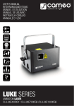
1
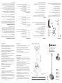
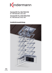
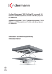
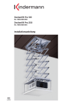
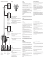
Schnellübersicht / At one glance / Apperçu
Montage
b
a
b
a
a
b
Rosette zur Abdeckung
b
Cover for the mounting
plate
Rosette pour cache de
l‘attache au plafond
Säule
Überprüfen Sie zuerst den Standort der Deckenhalterung nach Bildgrößentabelle und Keystone-Winkel des Projektors.
Führen Sie eine Testprojektion durch.
Innenliegende Kabelführung
Integrierte Absturzsicherung (Seil)
Integrated cable channel
Integrated crash
protection (rope)
Passage de câble interne
Sécurité anti-chute
(câble métallique)
Befestigen Sie über geeignete Halteschrauben und Dübel die Säule (1) am
festgelegten Standort.
(b) Bohrungen für die Anbringung von Trägerklemmen (Nr. 5873000000)
zur Montage an Rundrohr-Traversen.
Beachten Sie dabei die Lage der ankommenden Verbindungskabel zur innenliegenden Kabelführung.
Beachten Sie bitte die Sicherheitshinweise!
Mounting
Stepless telescopic
height adjustment
Column
Hauteur ajustable télescopique continue
Choose the location of the ceiling fixture according to the picture size chart
and the Keystone correction of your projector.
If in doubt, test the projection.
Fix the column (1) at the proper location with suitable holding screws and
plugs.
(a) Long holes for ceiling mounting
(b) Drill holes for fixing the clamps (No. 5873000000) when mounting the unit on tube-shaped supports.
Make sure that the connection cables can be inserted into the integrated cable
channel.
Observe the safety instructions!
Montage
Colonne
Vérifier le positionnement de la potence plafond selon la tabelle de grosseur
d’image et l’angle de correction Keystone du projecteur.
Schnellwechselvorrichtung
Gelenk für 3DNeigung
Abstandsbolzen
einstellbar
Quick exchange of
projector
Joint for 3D tilting
Adjustable distance
elements
Système de pose
pour changement
rapide
Articulation
d‘inclinaison 3D
Boulons d‘écartement
ajustables
Faire un test de projection.
Fixer à l’aide de vis et de chevilles appropriées la colonne (1) à l‘endroit
déterminé.
(a) Trous allongés pour montage plafond
(b) Trous pour l’attache de pinces de portée (N 5873000000) pour montage à traverses de scène.
o
Prenez compte de la position des câbles d‘entrée de raccordement par
rapport à la conduite interne de câbles.
Faire attention aux consignes de sécurité !
Kabelanschluss und Bildjustage
Projektorhalter (2)
Da die Fernbedienung den Projektor bei Nichtbenutzung nur in den Standby-Betrieb versetzt, empfehlen wir Ihnen, die Netzzuleitung mit einem
zusätzlichen Ein-/Ausschalter auszustatten.
Lockern Sie mit dem Gabelschlüssel 10 mm die Verschraubung (2c) des
Projektorhalters. Drehen Sie die vier Gewindeabstandsbolzen (2a) in die
Gewindebohrungen der Arme. Sie können unterschiedliche Höhenlagen der
Gewindebuchsen Ihres Projektors ausgleichen.
Legen Sie Ihren Projektor mit der Unterseite nach oben auf eine weiche
Unterlage.
Stellen Sie fest, welcher der Schraubensätze (3) zu den Gewindebuchsen Ihres
Projektors paßt und befestigen damit den Projektorhalter durch die vier Abstandsbolzen (2a). Setzen Sie dazu beidseitig die passenden U-Schreiben ein.
Ziehen Sie die Verschraubung des Projektorhalters (2c) an.
Lockern Sie jetzt die beiden Schrauben (2b) auf dem Projektorhalter soweit,
damit Sie die fertig montierte Einheit in die Schnellwechselvorrichtung der
montierten Säule einhängen können.
Sichern Sie die Verbindung durch Fixierung der beiden Schrauben.
Zum Abnehmen diese beiden Schrauben wieder lockern und Projektorhalter
seitlich abziehen.
Hinweise:
Die beiden Schrauben sind gegen Herausschrauben gesichert und sollten nicht
gewaltsam überdreht werden.
Das Modell „Comfort“ ist wegen des kurzen Deckenabstandes mit 2 Innensechskantschrauben bestückt.
Fixieren Sie die beiden Schrauben mit einem Innensechskantschlüssel
Größe 3 mm.
Verwenden Sie für die Verkabelung nur hochwertige abgeschirmte
Verbindungskabel.
Es empfiehlt sich zum besseren Einzug der Netz- und Signalleitungen, das
Teleskoprohr zusammenzuschieben, das innenliegende Sicherheitsseil als
Schlaufe herauszuziehen und mit den größten Kabelsteckern zu beginnen.
Schließen Sie die Netzleitung und alle Signalkabel lose an und nehmen
einen Projektionstest vor.
Alle Zuleitungen durch den innenliegenden Kabelkanal führen
(ausgenommen Modell „Comfort“).
Alle Verschraubungen überprüfen.
Aus Sicherheitsgründen ist die Absturzsicherung im Kabelkanal straff zu
halten. Deshalb ziehen Sie an der oberen Kabelöffnung das Drahtseil so
weit wie möglich aus dem Kanal. Diese Überlänge mit der Seilklemme (4)
fixieren und die so entstandene Schlaufe wieder in den Kabelkanal zurückschieben.
Achten Sie darauf, dass die Lüfteröffnungen des Projektors frei bleiben!
(a) Langlöcher für Deckenmontage
Stufenlose Teleskophöhenverstellung
Montage
Mounting
Power supply and picture adjustment
Projector holder (2)
As the remote control automatically switches to stand-by when the
projector is not in use, we recommend you to equip the power cable with
an additonal on/off switch.
Loosen the fastening screws (2c) of the adjustable carrying arms with the
spanner 10 mm. Insert the four distance elements (2a) into the drill-holes of
the carrying arms. Thus you can compensate different levels of the drill-holes
at the botton of your projector.
Put your data/video projector on a soft surface upside down.
Make sure to choose the proper sets of screws (3) which fit to your unit
and fasten the projector holder by putting the screws through the distance
elements (2a).
Also use the suitable washers on both sides of the distance elements.
Then fasten the screws of the projector holder (2c).
Now loosen the two Allen head screws (2b) on the projector holder so that
you can fix the pre-mounted unit at the quick-mounting device of the column.
Secure the construction by fixing the two screws again.
For taking off the projector loosen the two screws and pull off the projector
holder sidewards.
Note:
The two screws are protected against total removal and should not be turned
violently.
The model “Comfort” is equipped with 2 special M 6 screws (with integrated
screw head) because of the short distance to the ceiling.
Fix them with a special screw driver for hollow screws 3 mm.
Use only high-quality protected connection cables.
It is advisable to minimize the length of the telescopic column, to pull out
the safety rope and to start with the biggest plugs in order to have an
easier access for inserting the wiring.
Connect the power supply and the signal cables loosely and test the
projection.
Drive all the cables through the integrated cable channel (except model
„Comfort“).
Check the fastening of all screws.
For safety reasons keep the safety rope in the cable channel taut. Pull out
the rope through the upper opening of the cable channel as far as possible,
then fix the surplus length with the clamp (4). Push the loop of the rope
back into the cable channel.
Make sure that the ventilation grilles of the projector are unobstructed!
Montage
Support projecteur (2)
Dévisser les vis du support plafond à l’aide de clé ouvertes 10 mm.
Tournez les 4 boulons d’écartement (2a) dans le taraudage des bras. Avec ces
boulons vous pouvez compenser les différentes hauteurs des pieds d‘attache
de votre projecteur. Posez le projecteur avec sa face inférieure tournée vers le
haut sur une surface douce.
Choisir le set de vis (3) approprié aux pas de vis du projecteur, puis fixer à
l’aide de ces vis le projecteur à travers des boulons d’écartement (2a) avec les
rondelles correspondantes. Sérer les vis du support de projecteur (2c).
Desserrez maintenant les deux vis (2b) du support de projecteur de telle sorte
que vous puissiez fixer l‘unité complètement montée dans le système de pose
rapide de la colonne.
Sécurisez ensuite cet assemblage en resserrant ces deux vis.
Pour enlever le projecteur il faut dévisser ces deux vis puis retirer latéralement
le support de projecteur.
Remarques:
Ces deux vis sont sécurisées contre le démontage complet et ne devraient pas
être faussées. Le modèle „Comfort“ permet un montage très près du plafond
grâce à 2 vis à 6 pans.
Fixer les deux vis avec une clé à 6 pans de 3 mm.
Faire attention que les grilles de ventilation du projecteur ne soient pas
bloquées !
Connexion des câbles et réglage d‘image
En cas de non-utilisation la télécommande ne remet le projecteur qu‘en état
de veille.
C‘est pourquoi nous vous recommandons d‘équiper le câble de réseau d‘un
interrupteur supplémentaire.
N‘employez que des câbles de connexion de haute qualité.
Pour faciliter la mise en place des câbles de réseau et de signaux, nous vous
recommandons de faire coulisser la colonne télescopique vers le haut, d‘en
tirer le câble de sécurité et de commencer par les fiches les plus grandes.
Branchez tous les câbles de réseau et de signaux et faites un test de
projection.
Guidez tous les câbles d‘amenée à travers le conduit pour câbles
(sauf modèle „Comfort“).
Verifiez tous les serrages de vis.
Pour des raisons de sécurité il faudra garder le câble du système anti-chute
de façon rigide dans le conduit. Pour ce faire tirez le câble métallique autant
que possible hors de l‘ouverture supérieure du conduit.
Fixez-en le surplus avec le pince-câble (4) et remettez la boucle ainsi
produite dans le conduit de câbles.
Kindermann GmbH • Kindermannstrasse 2 • D-97199 Ochsenfurt
Tel.: +49 (0) 9331/93-0 • Fax: +49 (0) 9331/93-239 • www.kindermann.com
7436000000/7436000001/7437000000/7438000000 Änderungen vorbehalten/Subject to alterations
D/GB/F 0510 5 2 0.5 / 843 928
Modifications réservées Printed in Germany
5.2010
D
GB
F
Nr. 7438000000
Comfort 100
Nr. 7437000000
Comfort 60
Maße in mm/Dimensions in mm/
Dimensions en mm
Nr. 7436000001
Comfort 30
Nr. 7436000000
Comfort
Comfort 100 = 650–1000 mm
Comfort 60 = 450–610 mm
Comfort 30 = 300 mm
Comfort
= 120 mm
Deckenhalterungen
Ceiling Fixtures
Supports plafond
Lieferumfang
1
Technische Daten
Mounting kit
2
2b
Consignes de sécurité
In order not to roll up the cable or break it, do not turn the projector with the projector holder more than 180° in both directions.
Insert the screws 3 - 5 turns into the drill-holes of the projector.
Tauten the safety rope with the safety clamp after mounting.
When altering the position of the projector make sure that the connection cables are not damaged.
Please bear in mind your own liability!
We are not responsible for damages in case of incompetent mounting.
1 Column for ceiling mounting with cover and joint for 3D tilting
a) Telescopic height-adjustment with additional crash protection (Comfort 60/100)
b) Fastening screw for joint
2 Projector holder with 4 adjustable carrying arms
a) 4 distance elements for projector holder (supplied)
b) Allen head screws
c) Fastening screw for the carrying arms
3 4 sets of fastening screws M3 / M4 / M5 / M6
and washers (ø3,2 / ø4,3 / ø5,3 mm)
4 Clamp for safety rope
3
4x
4x
2c
2a
•
•
•
•
•
•
4
The following tools are required for the projector mounting:
1 Phillips screw driver, 1 spanner 10 mm, 1 spanner 7 mm,
1 screw driver for hollow screws 2 mm, 1 screw driver for hollow screws 3 mm
1a
1b
Livré avec
1
2
3
4
Vérifier en tout cas la force de tenue du plafond soit suffisante pour
projecteur et support.
Utiliser uniquement des vis de grosseur suffisante, qui sont spécialement concues pour le matériel de plafond rencontré. Ces vis ne sont pas livrées avec le support.
Vérifier que la solidité de la matière du plafond est convenable pour un montage définitif et qu’il y a aucun risque de chute.
Les matières de plafonds convenables sont: Bois dur, poutre d’acier, béton.
Faites un test de charge d’au moins le double du poids.
Faites attention aux responsabilités!
Nous ne sommes pas responsables en cas de montage non-approprié.
Le ventilateur du projecteur est chaud! Faites attention aux distances nécessaires pour la circulation d’air et la distance aux autres matériaux. L’appareil peut être endommagé à cause de surchauffe, ou il peut prendre feu!
Pour éviter l’enroulement du câble, ne tourner pas le projecteur à plus de 180° horizontalement.
Les vis doivent êtres au moins tournées 3 - 5 fois dans le pas de vis
(côté projecteur).
Après le montage définitif, il faudra maintenir rigide le câble de sécurité anti-chute au moyen de la pince de sécurité.
Les câbles doivent être assez longs pour que lors de nouvelle orientation du projecteur, ils ne subissent pas de tension.
Nous ne sommes pas responsables en cas de montage non-approprié.
Les installations électriques ne doivent être faites que par du personnel
compétant.
•
•
•
•
•
•
•
•
•
•
•
Maßskizze / Illustration / Schéma
Säule für Deckenmontage mit Rosette und Gelenk für 3D-Neigung
a) Teleskopvorrichtung mit Absturzsicherung (Comfort 60/100)
b) Feststellschraube für Gelenk
Projektorhalter mit 4 variablen Tragearmen
a) 4 Gewindeabstandsbolzen für Projektorhalter (beigelegt)
b) Innensechskantschrauben
c) Feststellschraube für die variablen Tragearme
4 Schraubensätze M3 / M4 / M5 / M6
mit U-Scheiben (ø3,2 / ø4,3 / ø5,3 mm)
Seilklemme für Absturzsicherung
1
2
3
4
Colonne pour montage au plafond avec rosette et articulation 3D
a) Tube téléscopique avec sécurité anti-chute (Comfort 60/100)
b) Vis de fixation pour articulation
Support de projecteur avec 4 bras porteurs variables
a) 4 boulons d’écartement pour support de projecteur (livré)
b) Vis à six pans creux
c) Vis de fixation pour les bras porteurs variables
4 sets de vis M3 / M4 / M5 / M6
et rondelles (ø3,2 / ø4,3 / ø5,3 mm)
Pince-câble pour sécurité anti-chute
Pour le montage du projecteur vous nécessitez des outils suivants:
1 tournevis cruciforme, 1 clé ouvertes 10 mm, 1 clé ouvertes 7 mm,
1 clé à six pans 2 mm, 1 clé à six pans 3 mm
Make sure that the construction of the ceiling is suitable for permanently holding the weight of the projector and the mounting kit.
Suitable materials to attach the mounting kit to are hard wood, metal or concrete surfaces.
Only use the proper screw dimensions which are suitable for the construction of the ceiling. Such screws are not included in the mounting kit!
After mounting the ceiling fixture, test the construction with at least twice the weight of the projector.
The airflow of the projector is hot! Make sure that the unit keeps its distance to other materials and that the flow of fresh air is not hampered.
The projector can be ruined by overheating.
•
•
•
•
•
•
•
•
•
•
•
•
Safety instructions
Als Werkzeuge zur Projektormontage benötigen Sie:
1 Kreuzschlitzschraubendreher, 1 Gabelschlüssel 10 mm, 1 Gabelschlüssel
7 mm, 1 Innensechskantschlüssel 2 mm, 1 Innensechskantschlüssel 3 mm
•
•
•
•
•
Safety instructions
Überzeugen Sie sich in jedem Fall von der ausreichenden Tragfähigkeit der Decke für Projektor und Deckenhalterung.
Benutzen Sie nur ausreichend dimensionierte Schrauben, die speziell für die vorhandene Deckenstruktur geeignet sind.
Diese Schrauben sind nicht im Lieferumfang enthalten!
Überprüfen Sie, ob das Deckenmaterial die für eine dauerhafte Montage erforderliche Festigkeit hat und keine Absturzgefahr der montierten
Einrichtung besteht. Geeignete Deckenstrukturen sind:
Hartholz – Stahlträger – Beton.
Führen Sie nach der Montage einen Belastungstest, mindestens mit der doppelten Belastung, durch.
Die Abluft des Projektors ist heiß! Auf ausreichende Belüftung und
Abstände zu anderen Materialien achten.
Durch Überhitzung kann das Gerät Schaden nehmen.
Um Kabelaufwicklungen, oder sogar Kabelbrüche zu vermeiden, drehen Sie den Projektor mit Projektorhalter horizontal nicht weiter als ± 180°.
Die Schraubensätze müssen jeweils 3 - 5 Umdrehungen ins Gewinde (Geräteseite) eingedreht sein.
Absturzsicherung nach fertiger Montage mittels der Sicherheitsklemme straff halten.
Die Anschlusskabel vom Projektor dürfen bei Neuausrichtung keinen übermäßigen Beanspruchungen ausgesetzt werden!
Bitte achten Sie auf die rechtlichen Haftungsfolgen!
Wir haften nicht bei unsachgemäßer Montage.
Sicherheitshinweise
Allgemeines / Justagemöglichkeiten
Kindermann Comfort 100
stufenlose Teleskop-Höheneinstellung von 65 – 100 cm
Nr. 7438000000
Kindermann Comfort 60
stufenlose Teleskop-Höheneinstellung von 45 – 61 cm
Nr. 7437000000
Kindermann Comfort 30
Abstand Projektor / Decke 30 cm
Nr. 7436000001
Kindermann Comfort
Abstand Projektor / Decke 12 cm
Nr. 7436000000
Der Befestigungsbereich der Gewindebohrungen in Ihrem Projektor sollte
in einem Durchmesserbereich von 75 bis 370 mm liegen. Eine Befestigung
mit nur 3 Tragearmen ist möglich. Das max. Projektorgewicht sollte 20 kg
nicht überschreiten.
Durch eine flexible Klemmung im Boden der Säule kann der eingesetzte
Projektor um ± 180° gedreht, sowie um ± 20° geneigt werden.
Nach kompletter Justage kann die Halteschraube (1b) mit einem Gabelschlüssel 10 mm nachgezogen werden, um die Projektionslage zu fixieren.
Die Modelle „Comfort 60 und Comfort 100“ besitzen ein Teleskoprohr mit
einem stufenlosen Einstellbereich zwischen 45 bis 61 cm und 65 bis 100 cm.
Zum Verschieben lockern Sie mit Hilfe eines Innensechskantschlüssels
2 mm die vier Klemmschrauben (1a).
Technical data
General instructions / Adjustment
Kindermann Comfort 100
Stepless telescopic height-adjustment 65 – 100 cm
No. 7438000000
Kindermann Comfort 60
Stepless telescopic height-adjustment 45 – 61 cm
No. 7437000000
Kindermann Comfort 30
Distance projector / ceiling 30 cm
No. 7436000001
Kindermann Comfort
Distance projector / ceiling 12 cm
No. 7436000000
The distance between the drill-holes on your projector for fixing the mounting kit must be between 75 and 370 mm. Mounting the projector with only
3 arms is possible. The maximum weight of the projector must not exceed
20 kg! By loosening the screw in the bottom of the column you can rotate
the projector by ± 180° and tilt it by ca. ± 20°.
After finishing the adjustment tighten the fastening screw (1b) with a
spanner 10 mm.
The models “Comfort 60 and Comfort 100” are equipped with a telescopic
column for stepless height-adjustment between 45 up to 61 cm and 65 up
to 100 cm. For adjustment loosen the four clamps (1a) with a screw driver
for hollow screws 2 mm.
Données techniques
Kindermann Comfort 100
Réglage télescopique de la hauteur entre 65 à 100 cm
No 7438000000
Kindermann Comfort 60
Réglage télescopique de la hauteur entre 45 à 61 cm
No 7437000000
Kindermann Comfort 30
Distance projecteur / plafond 30 cm
No 7436000001
Kindermann Comfort
Distance projecteur / plafond 12 cm
No 7436000000
Informations générales / Possibilités de réglage
Le domaine d’attaches de votre projecteur doit être entre 75 et 370 mm.
Fixation possible avec seulement 3 bras profilés.
Le poids maximum du projecteur ne doit pas dépasser 20 kg!
En dévissant la vis de bloquage dans le bas de la colonne (1), le projecteur
peut être tourné à ± 180° et incliné à ± 20°. Après l‘ajustage complet
resserrez le vis de fixation (1b) avec une clé 10 mm.
Les modèles „Comfort 60 et Comfort 100“ ont un tube télescopique avec
réglage graduel de la hauteur entre 45 et 61 cm et de 65 à 100 cm.
Pour régler la hauteur, dévisser les 4 vis de bloquage à l’aide d’une clé à
6 pans de 2 mm.