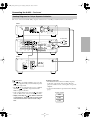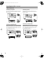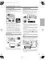
1
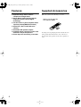
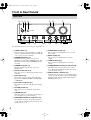
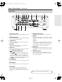
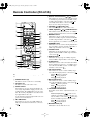
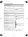
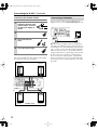
*En_A933_01.fm Page 1 Monday, December 20, 2004 1:23 PM
Contents
Integrated Amplifier
Introduction .................................... 2
A-933
Instruction Manual
Connections ................................. 10
Enjoying Audio Sources.............. 17
Thank you for purchasing an Onkyo Integrated Amplifier. Please read this manual thoroughly before making
connections and plugging in the unit.
Following the instructions in this manual will enable
you to obtain optimum performance and listening
enjoyment from your new Integrated Amplifier.
Please retain this manual for future reference.
Troubleshooting........................... 20
Specifications .............................. 22
En
*En_A933_02.fm Page 2 Tuesday, January 25, 2005 1:46 PM
WARNING:
TO REDUCE THE RISK OF FIRE OR ELECTRIC
SHOCK, DO NOT EXPOSE THIS APPARATUS
TO RAIN OR MOISTURE.
CAUTION:
TO REDUCE THE RISK OF ELECTRIC SHOCK,
DO NOT REMOVE COVER (OR BACK). NO
USER-SERVICEABLE PARTS INSIDE. REFER
SERVICING
TO
QUALIFIED
SERVICE
PERSONNEL.
WARNING
AVIS
RISK OF ELECTRIC SHOCK
DO NOT OPEN
RISQUE DE CHOC ELECTRIQUE
NE PAS OUVRIR
The lightning flash with arrowhead symbol, within an
equilateral triangle, is intended to alert the user to the
presence of uninsulated “dangerous voltage” within
the product’s enclosure that may be of sufficient
magnitude to constitute a risk of electric shock to
persons.
The exclamation point within an equilateral triangle is
intended to alert the user to the presence of important
operating and maintenance (servicing) instructions in
the literature accompanying the appliance.
Important Safety Instructions
1.
2.
3.
4.
5.
6.
7.
8.
9.
10.
11.
12.
13.
14.
2
Read these instructions.
Keep these instructions.
Heed all warnings.
Follow all instructions.
Do not use this apparatus near water.
Clean only with dry cloth.
Do not block any ventilation openings. Install in
accordance with the manufacturer’s instructions.
Do not install near any heat sources such as radiators, heat registers, stoves, or other apparatus
(including amplifiers) that produce heat.
Do not defeat the safety purpose of the polarized or
grounding-type plug. A polarized plug has two
blades with one wider than the other. A grounding
type plug has two blades and a third grounding
prong. The wide blade or the third prong are provided for your safety. If the provided plug does not
fit into your outlet, consult an electrician for
replacement of the obsolete outlet.
Protect the power cord from being walked on or
pinched particularly at plugs, convenience receptacles, and the point where they exit from the apparatus.
Only use attachments/accessories specified by the
manufacturer.
Use only with the cart, stand, PORTABLE CART WARNING
tripod, bracket, or table specified by the manufacturer, or
sold with the apparatus.
When a cart is used, use caution when moving the
cart/apparatus combination
to avoid injury from tip-over. S3125A
Unplug this apparatus during lightning storms or
when unused for long periods of time.
Refer all servicing to qualified service personnel.
Servicing is required when the apparatus has been
damaged in any way, such as power-supply cord or
plug is damaged, liquid has been spilled or objects
have fallen into the apparatus, the apparatus has
been exposed to rain or moisture, does not operate
normally, or has been dropped.
15. Damage Requiring Service
Unplug the apparatus from the wall outlet and refer
servicing to qualified service personnel under the
following conditions:
A. When the power-supply cord or plug is damaged,
B. If liquid has been spilled, or objects have fallen
into the apparatus,
C. If the apparatus has been exposed to rain or
water,
D. If the apparatus does not operate normally by
following the operating instructions. Adjust only
those controls that are covered by the operating
instructions as an improper adjustment of other
controls may result in damage and will often
require extensive work by a qualified technician
to restore the apparatus to its normal operation,
E. If the apparatus has been dropped or damaged in
any way, and
F. When the apparatus exhibits a distinct change in
performance this indicates a need for service.
16. Object and Liquid Entry
Never push objects of any kind into the apparatus
through openings as they may touch dangerous voltage points or short-out parts that could result in a
fire or electric shock.
The apparatus shall not be exposed to dripping or
splashing and no objects filled with liquids, such as
vases shall be placed on the apparatus.
Don’t put candles or other burning objects on top of
this unit.
17. Batteries
Always consider the environmental issues and follow local regulations when disposing of batteries.
18. If you install the apparatus in a built-in installation,
such as a bookcase or rack, ensure that there is adequate ventilation.
Leave 20 cm (8") of free space at the top and sides
and 10 cm (4") at the rear. The rear edge of the shelf
or board above the apparatus shall be set 10 cm (4")
away from the rear panel or wall, creating a flue-like
gap for warm air to escape.
*En_A933_02.fm Page 3 Tuesday, January 25, 2005 1:46 PM
Precautions
1. Recording Copyright—Unless it’s for personal use
only, recording copyrighted material is illegal without the permission of the copyright holder.
2. AC Fuse—The AC fuse inside the unit is not userserviceable. If you cannot turn on the unit, contact
your Onkyo dealer.
3. Care—Occasionally you should dust the unit all
over with a soft cloth. For stubborn stains, use a soft
cloth dampened with a weak solution of mild detergent and water. Dry the unit immediately afterwards
with a clean cloth. Don’t use abrasive cloths, thinners, alcohol, or other chemical solvents, because
they may damage the finish or remove the panel lettering.
4. Power
WARNING
BEFORE PLUGGING IN THE UNIT FOR THE
FIRST TIME, READ THE FOLLOWING SECTION CAREFULLY.
AC outlet voltages vary from country to country.
Make sure that the voltage in your area meets the
voltage requirements printed on the unit’s rear panel
(e.g., AC 230 V, 50 Hz or AC 120 V, 60 Hz).
Some models have a voltage selector switch for
compatibility with power systems around the world.
Before you plug in such a model, make sure that the
voltage selector is set to the correct voltage for your
area.
5. Never Touch this Unit with Wet Hands—Never
handle this unit or its power cord while your hands
are wet or damp. If water or any other liquid gets
inside this unit, have it checked by your Onkyo
dealer.
6. Handling Notes
• If you need to transport this unit, use the original
packaging to pack it how it was when you originally bought it.
• Do not leave rubber or plastic items on this unit
for a long time, because they may leave marks on
the case.
• This unit’s top and rear panels may get warm
after prolonged use. This is normal.
• If you do not use this unit for a long time, it may
not work properly the next time you turn it on, so
be sure to use it occasionally.
For British models
Replacement and mounting of an AC plug on the power
supply cord of this unit should be performed only by
qualified service personnel.
IMPORTANT
The wires in the mains lead are coloured in accordance
with the following code:
Blue:
Neutral
Brown: Live
As the colours of the wires in the mains lead of this
apparatus may not correspond with the coloured markings identifying the terminals in your plug, proceed as
follows:
The wire which is coloured blue must be connected to
the terminal which is marked with the letter N or
coloured black.
The wire which is coloured brown must be connected to
the terminal which is marked with the letter L or
coloured red.
IMPORTANT
The plug is fitted with an appropriate fuse. If the fuse
needs to be replaced, the replacement fuse must
approved by ASTA or BSI to BS1362 and have the same
ampere rating as that indicated on the plug. Check for
the ASTA mark or the BSI mark on the body of the fuse.
If the power cord’s plug is not suitable for your socket
outlets, cut if off and fit a suitable plug. Fit a suitable
fuse in the plug.
For European Models
Declaration of Conformity
We, ONKYO EUROPE
ELECTRONICS GmbH
LIEGNITZERSTRASSE 6,
82194 GROEBENZELL,
GERMANY
declare in own responsibility, that the ONKYO product
described in this instruction manual is in compliance with the
corresponding
technical standards such as EN60065,
EN55013, EN55020 and EN61000-3-2, -3-3.
GROEBENZELL, GERMANY
I. MORI
ONKYO EUROPE ELECTRONICS GmbH
3
*En_A933_02.fm Page 4 Tuesday, January 25, 2005 1:46 PM
4
Features
Supplied Accessories
❑ Separate design allows various
component configurations
❑ Stereo digital amp featuring Onkyo’s
unique VL (Vector Linear) Digital
technology
❑ Can be used as a power amplifier with a
separate preamp (MAIN IN function)
❑ Super Bass, Bass, and Treble tone
controls
❑ Selectable A/B speaker outputs
❑ Included remote controller can be used
with other Onkyo components
❑ Phono input for connecting a turntable
Make sure you have the following accessories:
Remote controller (RC-613S)
& two batteries (AA/R6)
ON
1
STA
NDB
Y
2
5
3
6
9
8
>10
AM
CD
4
7
10/0
FM
GROUP
CLE
AR
MD
TAP
VOL
PRES
ET
E /CD
R
UME
MUT
ING
VOL
TIM
MEM
ORY
RAND
OM
P MOD
E
CLO
CAL CK
L
RC -613
ER
PRES
ET
UME
SLE
EP
ENT
ER
REPE
AT
INP
DISP
LAY
UT
SCRO
LL
S
In catalogs and on packaging, the letter added to the end
of the product name indicates the color of the A-933.
Specifications and operation are the same regardless of
color.
*En_A933_02.fm Page 5 Tuesday, January 25, 2005 1:46 PM
Table of Contents
Introduction
Important Safety Instructions .................................................................................... 2
Precautions .................................................................................................................. 3
Features ....................................................................................................................... 4
Supplied Accessories ................................................................................................. 4
Table of Contents ........................................................................................................ 5
Front & Rear Panels .................................................................................................... 6
Front Panel ............................................................................................................ 6
Rear Panel............................................................................................................. 7
Remote Controller (RC-613S) ..................................................................................... 8
Installing the Batteries ........................................................................................... 9
Using the Remote Controller ................................................................................. 9
Connections
Connecting the A-933 ............................................................................................... 10
About the System Functions................................................................................ 10
Connecting Your Speakers.................................................................................. 11
Connecting a Subwoofer ..................................................................................... 12
Hookup Diagrams for Onkyo Separate Collection............................................... 13
Audio Components .............................................................................................. 14
Connecting a CD player ................................................................................... 14
Connecting an MD Recorder............................................................................ 14
Connecting a Tuner.......................................................................................... 14
Connecting a Cassette Deck............................................................................ 14
Connecting a Turntable.................................................................................... 15
Connecting a TV or Other Component with an Audio Output .......................... 15
Connecting a Preamp ...................................................................................... 15
Connecting Another Component’s Power Cord ............................................... 15
Connecting
Components ........................................................................... 16
Connecting the Power Cord ............................................................................. 16
Enjoying Audio Sources
Turning on the A-933........................................................................................... 17
Listening to Components..................................................................................... 17
Selecting Speaker Set A or B........................................................................... 17
Muting the A-933 (remote controller only)........................................................ 18
Using Headphones........................................................................................... 18
Using the Tone Controls...................................................................................... 18
Selecting Tone or Direct Mode......................................................................... 18
Adjusting the Super Bass................................................................................. 18
Adjusting the Bass ........................................................................................... 18
Adjusting the Treble ......................................................................................... 18
Using the MAIN IN Function ................................................................................ 19
Recording ............................................................................................................ 19
Others
Troubleshooting ........................................................................................................ 20
Specifications ............................................................................................................ 22
5
*En_A933_02.fm Page 6 Tuesday, January 25, 2005 1:46 PM
Front & Rear Panels
Front Panel
1 23 4
5 6
7
MD
LINE
TAPE /CDR
CD
STANDBY/ON
TUNER
ON(G)
STANDBY(R)
PHONO
SUPER BASS
POWER
ON
PHONES
OFF
8
A
SPEAKERS
BASS
B
9
TREBLE
TO N E ( R )
DIRECT (G )
MAX
0
A
B
MAIN IN
C D
For detailed information, refer to the pages in parentheses.
A POWER switch (17)
This is the main power switch. When set to OFF, the
A-933 is completely shutdown. When set to ON, the
A-933 can be set to On or Standby.
B STANDBY/ON button (17)
This button is used to set the A-933 to On or
Standby. For models with a [POWER] switch, this
button has no effect unless the [POWER] switch is
set to ON.
C STANDBY indicator (17)
This indicator lights up when the A-933 is in
Standby mode.
D Remote control sensor (9)
This sensor receives control signals from the remote
controller.
E Input selector (17)
This control is used to select from the following
input sources: PHONO, TUNER, CD, LINE, MD,
or TAPE/CDR.
F Input selector indicator (17)
These indicators show the currently selected input
source.
G VOLUME control (18)
This control is used to adjust the volume of the
A-933.
H PHONES jack (18)
This phone jack is for connecting a standard pair of
stereo headphones for private listening.
I SPEAKERS A/B buttons & indicators (17)
These buttons are used to select which speaker set,
A or B, outputs sound. The indicators show if each
speaker set is on or off.
6
J SUPER BASS control (18)
This control is for adjusting the level of very-low
bass sounds.
K BASS control (18)
This control is for adjusting the level of bass
sounds.
L TREBLE control (18)
This control is for adjusting the level of treble
sounds.
M TONE(R)/DIRECT(G) button & indicator (18)
This button is used to select Tone mode or Direct
mode. The indicator lights up red (R) in Tone mode;
green (G) in Direct mode.
N MAIN IN button & indicator (19)
When the A-933 is used as a power amplifier with a
separate preamp, this button is used to set the MAIN
IN function. The indicator lights up blue while the
MAIN IN function is on.
*En_A933_02.fm Page 7 Tuesday, January 25, 2005 1:46 PM
Front & Rear Panels—Continued
Rear Panel
1 2
3456
7
8
9
L
GND
L
L
R
R
SPEAKERS
B
A
R
PHONO (MM)
TUNER
L
LINE
CD
AC OUTLET
L
L
R
L
R
SUBWOOFER
PREOUT
R
MAIN IN
R
R
OUT
MD
IN
OUT
IN
TAPE/CDR
REMOTE
CONTROL
MODEL NO.A-933
A or B :
A + B:
4 OHMS MIN. /SPEAKER
8 OHMS MIN. /SPEAKER
C
A Grounding terminal
This terminal is for connecting a turntable’s ground
wire.
B PHONO (MM) input
This analog audio input is for connecting a turntable
with a moving-magnet cartridge.
C TUNER input
This analog audio input is for connecting a tuner’s
analog audio output.
D CD input
This analog audio input is for connecting a CD
player’s analog audio output.
E LINE input
This analog audio input is for connecting a component’s analog audio output (TV, etc).
F
AC 230-240V
50 Hz
UNSWITCHED
TOTAL 100W MAX.
CAUTION: SPEAKER IMPEDANCE
INTEGRATED AMPLIFIER
0 A B
L
REMOTE CONTROL jacks
These
(Remote Interactive) jacks can be connected to the
jacks on your other Onkyo audio
components. The A-933’s remote controller can
then be used to control all of your components. To
use
, you must make an analog audio connection
between the A-933 and each component.
J SUBWOOFER PREOUT
This jack is for connecting a powered subwoofer.
K MAIN IN
This analog audio input is for connecting a separate
preamp when you want to use the A-933 as a power
amplifier.
Caution:
Do not connect a component that does not have an
output volume control, such as a CD player, because
the sound will be output at maximum volume and
may damage the A-933 and your speakers.
L MD IN/OUT
This analog audio input and output are for connecting an MD recorder with an analog audio input and
output.
M TAPE/CDR IN/OUT
This analog audio input and output are for connecting a recorder (CD, cassette, etc) with an analog
audio input and output.
G SPEAKERS B
These terminal posts are for connecting speaker set
B.
H SPEAKERS A
These terminal posts are for connecting speaker set
A.
I AC OUTLET
This AC outlet can be used to supply power to
another audio component. The type of outlet
depends on the country in which you purchased the
A-933.
See pages 11–16 for connection information
7
*En_A933_02.fm Page 8 Tuesday, January 25, 2005 1:46 PM
Remote Controller (RC-613S)
E Reverse & Fast Forward [
1
2
3
4
STANDBY
ON
F VOLUME [ ]/[ ] buttons (18)
1
2
3
4
5
6
7
8
9
10/0
>10
GROUP
These buttons adjust the volume of the A-933.
G TIMER, Up/Down [ ]/[ ] & ENTER buttons
FM
AM
CLEAR
CD
MD
TAPE /CDR
5
A
B
C
D
E
H
I
VOLUME
F
6
PRESET
PRESET
MUTING
VOLUME
7
SLEEP
TIMER
G
H
I
ENTER
INPUT
8
9
0
]/[ ] buttons
These buttons are used for reverse and fast forward
on an Onkyo Separate Collection CD, MD, cassette,
or CDR component that’s connected via
. On
some Onkyo tuners that’re connected via
,
they’re used to change the frequency.
MEMORY
REPEAT
DISPLAY
RANDOM
P MODE
SCROLL
CLOCK
CALL
J
K
L
M
J
K
L
M
RC-613S
For detailed information, refer to the pages in parentheses.
A STANDBY button (17)
N
This button is used to set the A-933 to Standby.
B ON button (17)
This button is used to turn on the A-933.
C Number buttons
These buttons are used to enter track numbers. To
enter a single-digit number, simply press the corresponding button. The [10/0] button is used to enter
either 10 or 0. The [>10] button is used when entering 2-digit numbers above 10.
See the instruction manual supplied with each component for more information.
O
D FM & AM buttons
These buttons are used to select AM or FM on an
Onkyo Separate Collection tuner that’s connected
via
.
8
P
These buttons set the clock and timer on an Onkyo
Separate Collection tuner that’s connected via
.
MEMORY button
This button is used to set the memory playback
function on an Onkyo Separate Collection CD, MD,
or CDR component that’s connected via
. With
memory playback, you can make a custom program.
RANDOM button
This button is used to set the random playback function on an Onkyo Separate Collection CD, MD, or
CDR component that’s connected via
.
P MODE button
This button sets the playback mode on an Onkyo
Separate Collection MD or CDR component that’s
connected via
.
GROUP button
This button selects groups on an Onkyo Separate
Collection MD component that’s connected via
.
CLEAR button
This button is used to remove the last track from the
memory function program, etc., on an Onkyo Separate Collection CD, MD, cassette, or CDR component that’s connected via
.
CD control buttons
These buttons are used to control an Onkyo Separate Collection CD player that’s connected via
.
Pause [ ]: Pauses playback
Stop [ ]: Stops playback
Play [ ]: Starts playback
MD control buttons
These buttons are used to control an Onkyo Separate Collection MD player that’s connected via
.
Pause [ ]: Pauses playback
Stop [ ]: Stops playback
Play [ ]: Starts playback
TAPE/CDR control buttons
For double cassette decks, only Deck B can be controlled.
Reverse Play/Pause [ / ]: Starts reverse
playback on an Onkyo Separate Collection cassette deck that’s connected via
; pauses playback on an Onkyo Separate Collection CDR.
Stop [ ]: Stops playback
Play [ ]: Starts playback
MUTING button (18)
This button is used to mute the A-933.
*En_A933_02.fm Page 9 Tuesday, January 25, 2005 1:46 PM
Remote Controller (RC-613S)—Continued
Q Previous & Next [
]/[
] (PRESET [ ]
[ ]) buttons
These buttons are used to select the previous or next
track on an Onkyo Separate Collection CD, MD,
cassette, or CDR component that’s connected via
. Pressing them repeatedly selects earlier or later
tracks. On an Onkyo Separate Collection tuner,
they’re used to select radio presets.
R SLEEP button
This button is used to set the sleep function on an
Onkyo Separate Collection tuner that’s connected
via
.
Notes:
• The supplied batteries should last for about six
months, although this will vary with usage.
• If the remote controller doesn’t work reliably, try
replacing the batteries.
• Don’t mix new and old batteries or different types of
batteries.
• If you intend not to use the remote controller for a long
time, remove the batteries to prevent damage from
leakage or corrosion.
• Expired batteries should be removed as soon as possible to prevent damage from leakage or corrosion.
S INPUT [ ]/[ ] buttons (17)
These buttons are used to select from the following
input sources: PHONO, TUNER, CD, LINE, MD,
or TAPE/CDR.
T REPEAT button
This button is used to set the repeat playback functions on an Onkyo Separate Collection CD, MD, or
CDR component that’s connected via
.
Using the Remote Controller
Point the remote controller toward the remote control
sensor.
Remote control sensor
U DISPLAY button
This button is used to change the information shown
on the display.
V SCROLL button
This button is used to scroll text displayed on an
Onkyo Separate Collection MD or CDR component
that’s connected via
.
ON
1
Remove the battery
compartment cover, as
shown.
Insert the two supplied
batteries (AA/R6) in
accordance with the
polarity markings in
the battery compartment.
8
GROUP
MUTIN
G
PRESE
T
ME
Installing the Batteries
4
7
>10
CLEA
R
VOLU
This button is used to display the time on an Onkyo
Separate Collection tuner that’s connected via
.
DBY
3
6
10/0
AM
CD
/CDR
TIMER
W CLOCK CALL button
STAN
2
5
9
FM
MD
TAPE
VOLU
ME
PRESE
T
MEMOR
Y
RANDO
M
ENTE
R
REPEAT
P MODE
CLOC
CALL K
RC -613
S
INPUT
DISPLA
Y
SCROL
L
SLEEP
About 5 m
(16 feet)
Notes:
• The remote controller may not work reliably if the
A-933 is subjected to bright light, such as direct sunlight or inverter-type fluorescent lights. Keep this in
mind when installing.
• If another remote controller of the same type is used in
the same room, or the A-933 is installed close to
equipment that uses infrared rays, the remote controller may not work reliably.
• Don’t put anything, such as a book, on the remote controller, because the buttons may be pressed inadvertently, thereby draining the batteries.
• The remote controller may not work reliably if the
A-933 is installed in a rack behind colored glass doors.
Keep this in mind when installing.
• The remote controller will not work if there’s an obstacle between it and the A-933’s remote control sensor.
Replace the battery
compartment cover.
9
*En_A933_02.fm Page 10 Tuesday, January 25, 2005 1:46 PM
Connecting the A-933
About the System Functions
If you connect another component from the Onkyo Separate Collection to the A-933 with the appropriate
and audio
cables, you can use the following system functions.
cables are special cables solely for use with Onkyo products.
(No
cables are supplied with the A-933.)
Connecting components from the Onkyo Separate Collection.
See page 13 for more information.
Auto Power On
When you turn on the power or start playback on a component that’s connected to the A-933, the A-933 will turn on
automatically. And when you set the A-933 to Standby, all connected components will go on Standby as well. (The
A-933’s POWER switch must be set to ON for this to work.)
Direct Change
When playback is started on an audio component connected via
ponent as the input source.
, the A-933 will automatically select that com-
Remote Control Operation
You can control all components in your system by using the
A-933’s remote controller.
See page 16 for more information.
Program Timer
With an Onkyo tuner, you can program its timer to automatically start playback or recording at a specific time.
See the tuner’s instruction manual for
more information.
One-touch CD Dubbing
If your system comprises a CD player and CDR, MD recorder,
or cassette deck, you can dub an entire CD simply with one
press of a button.
Dubbing Individual Tracks
If your system comprises a CD player and MD recorder or
CDR, you can dub your favorite CD tracks individually with
one press of a button.
See your MD recorder’s, CDR’s, or
cassette deck’s instruction manual for
more information.
Synchro Recording
When using a CDR, MD recorder, or cassette deck to record
from a CD player, you can start the recording process simply
by starting playback on the CD player.
• Simply connecting an
cable will not enable the system functions. You must make an analog audio connection
between the A-933 and each component as well.
• See the instruction manual supplied with each component for more information about the
system functions.
• When using the A-933 as a power amplifier (MAIN IN function), the
system functions are unavailable.
10
*En_A933_02.fm Page 11 Tuesday, January 25, 2005 1:46 PM
Connecting the A-933—Continued
Before Making any Connections
RCA Audio Connection Color Coding
• Always refer to the instructions that came with the
component that you are connecting.
• Do not plug in the power cord until all connections have been properly made.
• Do not bind audio cables with power cords and
speaker cables. Doing so may adversely affect the
sound quality.
• To prevent interference, keep power cords and
speaker cables away from the tuner’s antenna.
• Red connectors are used for the right channel, and
white connectors are used for the left channel.
Left (white)
L
Right (red)
R
• Push each plug in all the way to make a good connection (loose connections can cause noise or malfunctions).
Right!
Wrong!
Connecting Your Speakers
Speaker Connection Precautions
You can connect one or two sets of speakers (A/B) to
the A-933, and select which set outputs sound, or use
both sets at the same time.
• Connecting one set of speakers (A or B): Only connect speakers with an impedance of 4 ohms or more
but less than 16 ohms. If you use speakers with a
lower impedance, and use the A-933 at high volume
levels for a long period of time, the built-in protection
circuit may be activated.
• Connecting two sets of speakers (A and B): Only
connect speakers with an impedance of 8 ohms or
more but less than 16 ohms. If you use speakers with
a lower impedance, and use the A-933 at high volume
levels for a long period of time, the built-in protection
circuit may be activated.
• Disconnect the power cord from the wall outlet
before making any connections.
• Read the instructions supplied with your speakers.
• Pay close attention to speaker wiring polarity. In other
words, connect positive (+) terminals to only positive
(+) terminals, and negative (–) terminals to only negative (–) terminals. If you get them the wrong way
around, the sound will be out of phase and will sound
unnatural.
• Unnecessarily long and very thin speaker cables may
affect the sound quality and should be avoided.
• Be careful not to short the
positive and negative wires.
Doing so may damage the
A-933.
• Don’t connect more than one
wire to each speaker terminal.
Doing so may damage the
A-933.
• Don’t connect a speaker to more than one pair of
speaker terminals.
SPEAKERS
B
R
L
R
A
L
11
*En_A933_02.fm Page 12 Tuesday, January 25, 2005 1:46 PM
Connecting the A-933—Continued
Connecting the Speaker Cables
1
Connecting a Subwoofer
Strip about 15 mm of insulation from the ends of the
speaker cables, and twist
the bare wires tightly, as
shown.
15 mm
You can connect a subwoofer with a built-in power
amplifier to the A-933’s SUBWOOFER PREOUT jack.
L
GND
L
L
R
R
SPEAKERS
B
A
R
PHONO (MM)
2
TUNER
Unscrew the terminal.
LINE
CD
L
L
AC OUTLET
L
R
L
SUBWOOFER
PREOUT
R
L
AC 230-240V
50 Hz
UNSWITCHED
TOTAL 100W MAX.
LINE INPUT
R
MAIN IN
R
OUT
MD
R
IN
OUT
IN
TAPE/CDR
REMOTE
CONTROL
CAUTION: SPEAKER IMPEDANCE
INTEGRATED AMPLIFIER
MODEL NO.A-933
A or B :
A + B:
4 OHMS MIN. /SPEAKER
8 OHMS MIN. /SPEAKER
LINE INPUT
3
Fully insert the bare
wires.
4
SUBWOOFER
PRE OUT
Screw the terminal tight.
The following illustration shows which speaker should
be connected to each pair of terminals.
Right
speaker
–
Left
speaker
Speaker set A
+
–
+
L
L
L
R
R
SPEAKERS
B
A
R
ONO (MM)
TUNER
L
LINE
CD
AC OUTLET
L
L
R
R
MAIN IN
R
R
OUT
MD
IN
OUT
IN
TAPE/CDR
L
R
L
REMOTE
CONTROL
AC 230-240V
50 Hz
UNSWITCHED
TOTAL 100W MAX.
CAUTION: SPEAKER IMPEDANCE
INTEGRATED AMPLIFIER
MODEL NO.A-933
A or B :
A + B:
4 OHMS MIN. /SPEAKER
8 OHMS MIN. /SPEAKER
A-933
–
+
Right
speaker
12
–
Speaker set B
+
Left
speaker
Tip: The volume and quality of the bass output from
your subwoofer will depend on its position, the shape of
your listening room, and your listening position. In general, a good bass sound can be obtained by installing the
subwoofer in a front corner, or at one-third of the way
along the wall in front of your listening position. To find
the best position for your subwoofer, while playing a
movie or some music with good bass, experiment by
placing your subwoofer at various positions within the
room, and choose the one that provides the most satisfying results.
*En_A933_02.fm Page 13 Tuesday, January 25, 2005 1:46 PM
Connecting the A-933—Continued
Hookup Diagrams for Onkyo Separate Collection
The A-933 can be used with the Onkyo Separate Collection C-733 CD Player and T-433 Tuner as shown below.
T-433
A-933
To wall outlet
L
GND
L
L
R
R
SPEAKERS
B
A
R
PHONO (MM)
TUNER
L
L
LINE
CD
AC OUTLET
L
R
L
R
SUBWOOFER
PREOUT
R
MAIN IN
R
OUT
MD
R
IN
OUT
IN
TAPE/CDR
REMOTE
CONTROL
L
AC 230-240V
50 Hz
UNSWITCHED
TOTAL 100W MAX.
CAUTION: SPEAKER IMPEDANCE
INTEGRATED AMPLIFIER
MODEL NO.A-933
A or B :
A + B:
4 OHMS MIN. /SPEAKER
8 OHMS MIN. /SPEAKER
C-733
DIGITAL
OUT OPTICAL
ANALOG
OUT
CONPACT DISC PLAYER
REMOTE
CONTROL
MODEL NO. C- 733
L
R
Connections
• No
cables are included with the A-933. Use the
cables supplied with your other Onkyo Separate
Collection components.
• The
jacks are used when the A-933 is combined
with other
-compatible components from the
Onkyo Separate Collection.
• Some components have two or more
jacks. These
jacks are all the same, and you can use any of them.
• Simply connecting an
cable will not enable the
system functions. You must make an analog audio
connection between the A-933 and each component.
Stacking Components
• The illustration below shows how Onkyo Separate
Collection components can be stacked. The CD
player is sensitive to heat, so don’t put it on top of the
amplifier.
• Connection information is provided on the following
pages.
Vertical stacking
T-433
A-933
C-733
13
*En_A933_02.fm Page 14 Tuesday, January 25, 2005 1:46 PM
Connecting the A-933—Continued
Audio Components
Connecting a CD player
Connecting a Tuner
Use an analog audio cable to connect the A-933’s CD
L/R jacks to the analog audio output jacks on the CD
player, as shown.
Use an analog audio cable to connect the A-933’s
TUNER L/R jacks to the analog audio output jacks on
the tuner, as shown.
L
L
GND
L
L
R
R
PHONO (MM)
LINE
CD
TUNER
L
L
R
R
L
R
L
R
SUBWOOFER
PREOUT
SPEAKERS
B
A
PHONO (MM)
V
CD AC 230-240
50 Hz
TUNER
LINE
CD
L
L
UNSWITCHED
TOTAL 100W MAX.
AC OUTLET
L
R
L
R
L
SUBWOOFER
PREOUT
R
MAIN IN
R
R
OUT
MD
IN
IN
OUT
TAPE/CDR
REMOTE
CONTROL
R
CAUTION: SPEAKER IMPEDANCE
A or B :
A + B:
INTEGRATED AMPLIFIER
MODEL NO.A-933
R
R
AC OUTLET
L
L
L
A
R
R
L
L
GND
SPEAKERS
B
4 OHMS MIN. /SPEAKER
8 OHMS MIN. /SPEAKER
R
OUT
MAIN IN
MD
R
IN
IN
OUT
TAPE/CDR
REMOTE
CONTROL
AC 230-240V
TUNER
50 Hz
UNSWITCHED
TOTAL 100W MAX.
CAUTION: SPEAKER IMPEDANCE
A or B :
A + B:
INTEGRATED AMPLIFIER
MODEL NO.A-933
4 OHMS MIN. /SPEAKER
8 OHMS MIN. /SPEAKER
OUT
ANALOG
OUT
L
L
R
R
Connecting an MD Recorder
Connecting a Cassette Deck
Use an analog audio cable to connect the A-933’s MD
IN L/R jacks to the MD recorder’s analog audio output
jacks, and use another analog audio cable to connect the
A-933’s MD OUT L/R jacks to the MD recorder’s analog audio input jacks, as shown.
Use an analog audio cable to connect the A-933’s
TAPE/CDR IN L/R jacks to the cassette deck’s output
jacks, and use another analog audio cable to connect the
A-933’s TAPE/CDR OUT L/R jacks to the cassette
deck’s input jacks, as shown.
L
L
SPEAKERS
B
R
R
L
A
R
PHONO (MM)
TUNER
L
L
R
R
PHONO (MM)
LINE
CD
L
L
L
SPEAKERS
B
A
R
TUNER
AC OUTLET
L
R
L
R
L
SUBWOOFER
PREOUT
L
AC 230-240V
50 Hz
UNSWITCHED
TOTAL 100W MAX.
LINE
CD
AC OUTLET
L
L
R
L
R
L
SUBWOOFER
PREOUT
R
R
OUT
MD
R
IN
OUT
IN
TAPE/CDR
OUT
IN
CAUTION: SPEAKER IMPEDANCE
MD
REMOTE
CONTROL
A or B :
A + B:
INTEGRATED AMPLIFIER
MODEL NO.A-933
4 OHMS MIN. /SPEAKER
8 OHMS MIN. /SPEAKER
L
R
REC PLAY
(IN) (OUT)
R
MAIN IN
R
R
OUT
MD
IN
OUT
IN
TAPE/CDR
AC 230-240V
50 Hz
UNSWITCHED
TOTAL 100W MAX.
R
OUT
IN
TAPE/CDR
CAUTION: SPEAKER IMPEDANCE
R
MAIN IN
14
L
GND
L
GND
REMOTE
CONTROL
A or B :
A + B:
INTEGRATED AMPLIFIER
MODEL NO.A-933
L
L
R
R
4 OHMS MIN. /SPEAKER
8 OHMS MIN. /SPEAKER
L
R
REC PLAY
(IN) (OUT)
*En_A933_02.fm Page 15 Tuesday, January 25, 2005 1:46 PM
Connecting the A-933—Continued
Connecting a Turntable
Connecting a Preamp
The A-933’s PHONO input jacks are for use with moving-magnet (MM) type cartridges.
Use an analog audio cable to connect the A-933’s
PHONO L/R jacks to the audio output jacks on the turntable, as shown.
The A-933 can be used as a power amplifier with a separate preamp.
In this case, use an analog audio cable to connect the
A-933’s MAIN IN jacks to the preamp’s output jacks.
Connect the speakers to the A-933, and connect the
playback components to the preamp.
L
GND
L
L
R
R
SPEAKERS
B
L
GND
A
L
L
R
R
R
PHONO (MM)
LINE
CD
TUNER
L
AC OUTLET
L
L
L
R
AC 230-240V
50 Hz
UNSWITCHED
TOTAL 100W MAX.
L
R
SUBWOOFER
PREOUT
SPEAKERS
B
TUNER
LINE
CD
L
L
L
R
R
R
L
R
R
R
R
OUT
MAIN IN
MD
IN
IN
OUT
TAPE/CDR
A
R
PHONO (MM)
L
R
L
SUBWOOFER
PREOUT
REMOTE
CONTROL
CAUTION: SPEAKER IMPEDANCE
A or B :
A + B:
INTEGRATED AMPLIFIER
MODEL NO.A-933
R
4 OHMS MIN. /SPEAKER
8 OHMS MIN. /SPEAKER
MAIN IN
OUT
MD
IN
MAIN IN
OUT
IN
TAPE/CDR
REMOTE
CONTROL
INTEGRATED AMPLIFIER
MODEL NO.A-933
AUDIO OUT
L
PRE OUT
L
L
R
R
PHONO (MM)
R
Ground wire
Notes:
• If the turntable has a ground wire, connect it to
A-933’s GND terminal. With some turntables, connecting the ground wire may cause hum, in which
case it should be disconnected.
• If the turntable has a moving-coil (MC) type cartridge, you’ll need a commercially available MC
phono preamp. In this case, connect the turntable to
the phono preamp’s input, and connect the phono
preamp’s output to the A-933’s PHONO L/R jacks.
Connecting a TV or Other Component with
an Audio Output
Use an analog audio cable to connect the A-933’s LINE
L/R jacks to the analog audio output jacks on the TV or
other component, as shown.
L
L
R
R
SPEAKERS
B
A
Connecting Another Component’s Power
Cord
The A-933 has an AC OUTLET on its rear panel. This
can be used to connect the power cord of another audio
component that you intend to use with the A-933.
L
L
GND
Notes:
• Do not connect a component that does not have an
output volume control, because the sound will be output at maximum volume and may damage the A-933
and your speakers.
• To turn on the MAIN IN function, press the [MAIN
IN] button for 3 seconds until the indicator lights up
blue (page 19).
• When the A-933 is used as a power amplifier, the
remote controller and the following functions are disabled: Volume control, Muting,
system functions,
Tone/Direct function, subwoofer output, and Recording. Some of these functions can be performed on the
connected preamp.
R
R
PHONO (MM)
TUNER
L
LINE
CD
AC OUTLET
LINE
AC 230-240V
L
L
R
L
R
50 Hz
L
UNSWITCHED
TOTAL 100W MAX.
SUBWOOFER
PREOUT
L
R
MAIN IN
R
R
OUT
MD
IN
OUT
IN
TAPE/CDR
REMOTE
CONTROL
CAUTION: SPEAKER IMPEDANCE
A or B :
A + B:
INTEGRATED AMPLIFIER
MODEL NO.A-933
4 OHMS MIN. /SPEAKER
8 OHMS MIN. /SPEAKER
AC OUTLET
SPEAKERS
B
A
R
LINE
CD
AC OUTLET
L
R
R
OUT
IN
TAPE/CDR
L
REMOTE
CONTROL
R
L
AC 230-240V
50 Hz
UNSWITCHED
TOTAL 100W MAX.
AC 230-240V
50 Hz
UNSWITCHED
TOTAL 100W MAX.
CAUTION: SPEAKER IMPEDANCE
INTEGRATED AMPLIFIER
MODEL NO.A-933
A or B :
A + B:
4 OHMS MIN. /SPEAKER
8 OHMS MIN. /SPEAKER
AUDIO OUT
L
R
Note:
If your TV has no audio output, you can connect the
A-933 to an audio output on your VCR and use its tuner.
Caution:
• Make sure that the maximum power requirement of
the component connected to the AC OUTLET does
not exceed the capacity printed on the A-933’s rear
panel (100W).
15
*En_A933_02.fm Page 16 Tuesday, January 25, 2005 1:46 PM
Connecting the A-933—Continued
Connecting
Components
With
(Remote Interactive), you can control your
-compatible Onkyo CD player, Tuner, and so on
with the A-933’s remote controller.
• To use
, you must make an analog audio connection between the A-933 and each audio component.
Connecting the Power Cord
• Before connecting the power cord, connect all your
speakers and audio components.
• Turning on the A-933 may cause a momentary power
surge, which might interfere with other electrical
equipment on the same circuit. If this is a problem,
plug the A-933 into a different branch circuit.
Tuner (T-433) etc.
ACCUCLOCK
TUNING
PRESET
CLEAR
MEMORY
FM MODE
STANDBY/ON
KEY MODE
BAND
CHARACTER
TUNING / PRESET
DISPLAY
STANDBY
A-933 (Preamp)
To wall outlet
MD
LINE
TAPE /CDR
CD
STANDBY/ON
TUNER
ON(G)
STANDBY(R)
PHONO
SUPER BASS
POWER
ON
OFF
PHONES
A
SPEAKERS
B
BASS
MAX
TREBLE
TONE(R)
DIRECT(G)
MAIN IN
ON
STANDBY
1
5
9
2
6
10/0
3
7
4
8
>10
GROUP
FM
AM
CD
CLEAR
MD
TAPE
/CDR
VOLUME
PRESET
MUTING
PRESET
VOLUME
SLEEP
TIMER
ENTER
MEMORY
INPUT
REPEAT
DISPLAY
RANDOM
CD Player (C-733) etc.
P MODE
SCROLL
CLOCK
CALL
RC -613
S
STANDBY/ON
DISPLAY
STANDBY
Notes:
• Push each plug in all the way to make a good connection.
• Use only dedicated
cables for
connections.
(No
cables are supplied with the A-933.)
• The A-933 has four
jacks. They’re all the same,
so you can use any of them.
•
jacks should be connected to only Onkyo components. Connecting them to another manufacturer’s
component may cause it to malfunction.
• Some components may not support all
functions.
See the manuals supplied with your other Onkyo
components for more information.
16
*En_A933_02.fm Page 17 Tuesday, January 25, 2005 1:46 PM
Enjoying Audio Sources
Turning On the A-933
Listening to Components
Input selector
STANDBY/ON
STANDBY indicator
MD
LINE
Volume
SPEAKERS A, B
STANDBY
ON /CDR
TAPE
MD
STANDBY
ON
STANDBY
CD
STANDBY/ON
LINE
TAPE /CDR
CD
STANDBY/ON
TUNER
1
2
3
4
ON(G)
STANDBY(R)
PHONO
5
SUPER BASS
POWER
BASS
TREBLE
9
6
7
8
10/0
>10
GROUP
ON
PHONES
OFF
A
SPEAKERS
B
MAX
FM
AM
TO N E ( R )
DIRECT (G )
1
2
5
6
9
10/0
3
4
ON(G)
STANDBY(R)
PHONO
SUPER BASS
POWER
ON
TUNER
7
>10
BASS
8
GROUP
TREBLE
MAIN IN
CLEAR
ON
OFF
PHONES
A
SPEAKERS
B
FM
MAX
AM
CLEAR
TO N E ( R )
DIRECT (G )
MAIN IN
CD
CD
MD
POWER
MD
TAPE /CDR
TAPE /CDR
VOLUME
1
Press the [POWER] button.
The STANDBY indicator lights up.
VOLUME
/
POWER
PRESET
MUTING
PRESET
MUTING
VOLUME
SLEEP
TIMER
ON
OFF
ENTER
Selecting Speaker Set A or B
2
STANDBY/ON
Remote
controller
ON
Press the [STANDBY/ON] button.
Alternatively, press the remote controller’s [ON] button.
The A-933 turns on and the
STANDBY indicator lights up green.
Note:
When it’s turned on, the A-933 outputs
no sound for about five seconds. This
allows the circuits to stabilize.
To turn off the A-933, press the
[STANDBY/ON] button. The A-933
will enter Standby mode.
If the A-933 is connected to other components via
, press the remote controller’s [ON] button once
to turn on the A-933, and press it again to turn on the
other components.
You can select which set of speakers outputs sound, or
you can use both sets at the same time.
To output sound from the speakers connected to the
SPEAKERS A terminals, press the SPEAKERS [A]
button. The indicator above that button will light up. If a
subwoofer is connected, that too will output sound.
To output sound from the speakers connected to the
SPEAKERS B terminals, press the SPEAKERS [B]
button. The indicator above that button will light up. If a
subwoofer is connected, that too will output sound.
To output sound from all connected speakers, press the
SPEAKERS [A] and SPEAKERS [B] button so that
both indicators are on.
1
MD
LINE
CD
Turning on all system components simultaneously:
You can set the A-933 so that all connected
components are turned on with just one press of the remote controller’s [ON] button or the A-933’s [STANDBY/ON]
button. To do this, turn on the A-933, and then press and
hold the remote controller’s [ON] button for 16 seconds
until the A-933 switches to Standby mode. You will then
be able to turn on the A-933 and all system components
with just one press of the remote controller’s [ON] button or the [STANDBY/ON] button on any system component.
Notes:
• The A-933 is shipped with the POWER switch in the
ON position ( ). When the power cord is connected
for the very first time, the A-933 will go on Standby,
and the STANDBY indicator will light up.
• To completely shut down the A-933, set the POWER
switch to the OFF position ( ).
TUNER
PHONO
TAPE /CDR
Turn the input selector to select
the component that you want to
listen to.
TAPE/CDR: Select to hear the component connected to the TAPE/CDR IN
jacks.
MD: Select to listen to the component
connected to the MD IN jacks.
LINE: Select to listen to the component connected to the LINE jacks.
CD: Select to listen to the component
connected to the CD jacks.
TUNER: Select to listen to the component connected to the TUNER jacks.
PHONO: Select to listen to the turntable connected to the PHONO jacks.
17
*En_A933_02.fm Page 18 Tuesday, January 25, 2005 1:46 PM
Enjoying Audio Sources—Continued
2
3
Start playback on the selected
component.
A-933
Remote
controller
To adjust the volume, use the
A-933’s Volume control, or the
remote controller’s VOLUME
[ ]/[ ] buttons.
Turn VOLUME control clockwise to
increase the volume or counterclockwise to decrease the volume.
VOLUME
Notes:
• Always turn down the volume before connecting your
headphones.
• All connected speakers are turned off while the headphones plug is inserted in the PHONES jack.
• The headphones output no sound while the MAIN IN
function is on.
Using the Tone Controls
While the MAIN IN function is on, the A-933’s tone
controls have no effect.
TONE(R)/DIRECT (G)
MD
LINE
TAPE /CDR
CD
STANDBY/ON
VOLUME
TUNER
ON(G)
STANDBY(R)
PHONO
SUPER BASS
POWER
ON
OFF
PHONES
A
SPEAKERS
B
BASS
Muting the A-933 (remote controller only)
You can temporarily mute the output of the A-933.
1
MUTING
Press the remote controller’s
[MUTING] button.
The A-933 is muted, and the
STANDBY indicator flashes green.
To unmute the A-933, press the
[MUTING] button again.
Notes:
• The Mute function will be cancelled
if the remote controller’s VOLUME
buttons are pressed or the A-933 is
set to Standby.
• When using the A-933 as a power
amplifier (MAIN IN function), the
Muting function has no effect.
Using Headphones
You can connect a pair of stereo headphones (1/4-inch
phone plug) to the A-933’s PHONES jack for private
listening.
STANDBY/ON
ON(G)
STANDBY(R)
PHONES
SUPER BASS
POWER
ON
18
OFF
PHONES
A
SPEAKERS
B
TREBLE
TO N E ( R )
DIRECT (G )
MAX
SUPER BASS
MAIN IN
TREBLE
BASS
Selecting Tone or Direct Mode
The [TONE(R)/DIRECT(G)] button is
used to select Tone or Direct mode.
In Tone mode, the tone controls can be
TONE(R)
DIRECT(G)
used to adjust the sound, and the
TONE/DIRECT indicator lights up red
(R).
In Direct mode, the tone controls are bypassed, so you
can enjoy a pure sound. The TONE/DIRECT indicator
lights up green (G).
Adjusting the Super Bass
The SUPER BASS control
adjusts very-low bass sounds.
Turn it up to make them louder.
Normally, it should be fully
turned down.
SUPER BASS
MAX
Adjusting the Bass
The BASS control adjusts bass
sounds. Turn it up to make them
louder. Turn it down to make them
quieter. Normally, it should be set
midway.
BASS
Adjusting the Treble
The TREBLE control adjusts treble
sounds. Turn it up to make them
louder. Turn it down to make them
quieter. Normally, it should be set
midway.
TREBLE
*En_A933_02.fm Page 19 Tuesday, January 25, 2005 1:46 PM
Enjoying Audio Sources—Continued
Using the MAIN IN Function
Recording
You can use the A-933 as power amplifier with a separate preamp. See page 15 for connection information.
MD
LINE
TAPE /CDR
CD
STANDBY/ON
TUNER
Unless you have the full consent of the
copyright holder, copyright laws prohibit
using your recordings for anything other
than personal enjoyment!
ON(G)
STANDBY(R)
PHONO
SUPER BASS
POWER
ON
OFF
PHONES
A
SPEAKERS
B
BASS
MAX
TREBLE
TO N E ( R )
DIRECT (G )
MAIN IN
Input selector
MAIN IN
MD
LINE
TAPE /CDR
CD
STANDBY/ON
TUNER
1
MAIN IN
ON(G)
STANDBY(R)
Press the [MAIN IN] button for 3
seconds until the MAIN IN indicator lights up.
The MAIN IN function comes on and
the MAIN IN indicator lights up blue.
While the MAIN IN function is on,
only audio from components connected to the preamp can be output.
PHONO
SUPER BASS
POWER
ON
1
MD
LINE
TAPE /CDR
OFF
PHONES
A
SPEAKERS
B
BASS
MAX
TREBLE
TO N E ( R )
DIRECT (G )
MAIN IN
Use the input selector to select
the component that you want to
record from.
CD
TUNER
To turn the MAIN IN function off,
press the [MAIN IN] button for 3 seconds until the MAIN IN indicator goes
off.
Notes:
• Do not connect a component that
does not have an output volume control to the MAIN IN jacks and use the
MAIN IN function, because the
sound will be output at maximum
volume and may damage the A-933
and your speakers.
• While the MAIN IN function is on,
the A-933’s Volume control has no
effect. Before you turn off the
MAIN IN function, make sure that
the Volume control is not turned up
high, to prevent any loud surprises.
• While the MAIN IN function in on,
the remote controller and the following A-933 functions are disabled:
Volume control, Muting,
system
functions, Tone/Direct function, subwoofer output, and Recording. Some
of these functions can be performed
on the connected preamp.
PHONO
2
Prepare the recorder:
• Set the recorder so that it’s ready for
recording.
• If necessary, adjust the recording
level on the recorder.
• See the recorder’s manual for more
information.
3
Start playback on the component
selected in step 1.
Note:
If you select another input source during recording, the newly selected input
source will be recorded.
Notes:
• You can record on a recorder that’s connected to the
MD OUT or TAPE/CDR OUT L/R jacks.
• The tone controls have no effect on the signal being
recorded.
• When using the A-933 as a power amplifier (MAIN
IN function), recording is not possible.
• For information on one-touch CD dubbing, individual
CD track dubbing, and timed recording with Onkyo
Separate Collection components, see page 10.
19
*En_A933_02.fm Page 20 Tuesday, January 25, 2005 1:46 PM
Troubleshooting
If you have any trouble using the A-933, look for a solution here. If you can’t resolve the issue yourself, contact your
Onkyo dealer.
Power
Can’t turn on the A-933.
• Make sure that the power cord is properly plugged into the wall outlet.
• Unplug the power cord from the wall outlet, wait five seconds or more, then plug it in again.
• By default, pressing the A-933’s [STANDBY/ON] button once does not turn on all of the system components. You
need to press the remote controller’s [ON] button again. Alternatively, you can set the A-933 so that all components
do turn on simultaneously (page 17).
The STANDBY indicator is flashing red.
• The amp protection circuit has been activated. Remove the power cord from the wall outlet immediately and contact
your Onkyo dealer.
Audio
There’s no sound or it’s very quiet.
• When the A-933 is used as a power amplifier (MAIN IN indicator lights up blue), the sound from components connected to the preamp are output. To output the sound from a component that’s connected to the A-933, or to use the
A-933 as a preamp, press the [MAIN IN] button for 3 seconds until the MAIN IN indicator goes off.
• Make sure that all audio plugs are pushed in all the way (page 11).
• Make sure that the inputs and outputs of all components are connected properly.
• Make sure that the polarity of the speaker cables is correct and that the bare wires are in contact with the metal part
of each speaker terminal (page 12).
• Make sure that the correct input source is selected (page 17).
• If the STANDBY indicator is flashing green, press the remote controller’s [MUTING] button to unmute the A-933
(page 18).
• Make sure that none of the cables are bent, twisted, or damaged.
• Make sure that SPEAKERS A or B are selected. When only SPEAKERS A is selected (A indicator on), speakers
connected to the SPEAKERS A terminals, and a connected subwoofer will output sound. When only SPEAKERS B
is selected (B indicator on), speakers connected to the SPEAKERS B terminals, and a connected subwoofer will
output sound.
• To use a turntable with a moving-coil (MC) type cartridge, you need a commercially available MC phono preamp
(page 15).
Noise can be heard.
• Using cable ties to bundle audio cables with power cords, speaker cables, and so on may degrade the audio performance, so don’t bundle them together.
• An audio cable may be picking up interference. Try repositioning your cables.
The tone controls don’t work.
• If the TONE/DIRECT indicator is green, Direct mode is selected and the tone controls have no effect. Press the
[TONE/DIRECT] button to select Tone mode. The TONE/DIRECT indicator will turn red (page 18).
Remote Controller
The remote controller doesn’t work.
• Make sure that the batteries are installed with the correct polarity (page 9).
• Install new batteries. Don’t mix different types of batteries or old and new batteries (page 9).
• Make sure that the remote controller is not too far away from the A-933 and that there’s no obstruction between the
remote controller and the A-933’s remote control sensor (page 9).
• Make sure that the A-933 is not subjected to direct sunshine or inverter-type florescent lights. Relocate if necessary
(page 9).
• If the A-933 is installed in a rack or cabinet with colored glass doors, the remote controller may not work reliably
when the doors are closed (page 9).
Can’t control other components?
• If it’s an Onkyo component, make sure that the
only an
cable won’t work.
20
cable and analog audio cable are connected properly. Connecting
*En_A933_02.fm Page 21 Tuesday, January 25, 2005 1:46 PM
Troubleshooting—Continued
Recording
Can’t record.
• The component connected to the MAIN IN jacks cannot be recorded.
• When using the A-933 as a power amplifier (MAIN IN function), recording is not possible.
Others
The VOLUME control doesn’t work.
• When using the A-933 as a power amplifier (MAIN IN function), the Volume control has no effect. Adjust the volume
on the connected preamp instead.
The Muting function doesn’t work.
• When using the A-933 as a power amplifier (MAIN IN function), the Muting function does not work. Use the muting
function on the connected preamp instead.
The A-933 contains a microcomputer for signal processing and control functions. In very rare
situations, severe interference, noise from an external source, or static electricity may cause it to
lock up. In the unlikely event that this happens, unplug the power cord from the wall outlet, wait at
least five seconds, and then plug it back in again.
Onkyo is not responsible for damages (such as CD rental fees) due to unsuccessful recordings
caused by the unit’s malfunction. Before you record important data, make sure that the material
will be recorded correctly.
To reset the A-933 to its factory defaults, with it turned on, while holding down the [MAIN IN]
button, press the [STANDBY/ON] button. The input selector indicators light up briefly, and then the
A-933 enters Standby mode.
21
*En_A933_02.fm Page 22 Tuesday, January 25, 2005 1:46 PM
Specifications
Speaker impedance:
80 W + 80 W (8 Ω, 1 kHz, DIN)
270 W + 270 W (3 Ω, Front)
220 W + 220 W (4 Ω, Front)
110 W + 110 W (8 Ω, Front)
0.08% (1 kHz, 1 W)
25 (Front, 1 kHz, 8 Ω)
200 mV, 50 kΩ (LINE)
2.5 mV, 50 kΩ (PHONO MM)
200 mV, 2.2 kΩ (REC OUT)
130 mV (MM, 1 kHz, 0.5%)
10 Hz–60 kHz, +1 dB–3 dB (CD)
+8 dB, –8 dB, 100 Hz (BASS)
+8 dB, –8 dB, 20 kHz (TREBLE)
+10 dB, 80 Hz (SUPER BASS)
100 dB (LINE, IHF-A)
70 dB (PHONO, IHF-A)
4–16 Ω
Power supply:
Power consumption:
Stand-by power consumption:
Dimensions (W × H × D):
Weight:
AC 230-240 V, 50 Hz
100 W
0.9 W
275 × 103 × 328 mm
7.5 kg
Analog inputs:
Analog outputs:
Subwoofer pre outputs:
Speaker outputs:
Phones:
PHONO, TUNER, CD, LINE, MD, TAPE/CDR, MAIN IN
MD, TAPE/CDR
1
2 (A, B)
1
Power output:
Dynamic power:
THD (total harmonic distortion):
Damping factor:
Input sensitivity and impedance:
Output level and impedance:
Phono overload:
Frequency response:
Tone control:
SN ratio:
Specifications and features are subject to change without notice.
22
*En_A933_02.fm Page 23 Tuesday, January 25, 2005 1:46 PM
23
*En_A933_02.fm Page 24 Tuesday, January 25, 2005 1:46 PM
Sales & Product Planning Div. : 2-1, Nisshin-cho, Neyagawa-shi, OSAKA 572-8540, JAPAN
Tel: 072-831-8023 Fax: 072-831-8124
ONKYO U.S.A. CORPORATION
18 Park Way, Upper Saddle River, N.J. 07458, U.S.A.
Tel: 201-785-2600 Fax: 201-785-2650 http://www.us.onkyo.com/
ONKYO EUROPE ELECTRONICS GmbH
Liegnitzerstrasse 6, 82194 Groebenzell, GERMANY
Tel: +49-8142-4401-0 Fax: +49-8142-4401-555 http://www.eu.onkyo.com/
ONKYO EUROPE UK Office
Suite 1, Gregories Court, Gregories Road, Beaconsfield, Buckinghamshire, HP9 1HQ
UNITED KINGDOM Tel: +44-(0)1494-681515 Fax: +44(0)-1494-680452
ONKYO CHINA LIMITED
Units 2102-2107, Metroplaza Tower I, 223 Hing Fong Road, Kwai Chung,
N.T., HONG KONG Tel: 852-2429-3118 Fax: 852-2428-9039
http://www.ch.onkyo.com/
HOMEPAGE
http://www.onkyo.com/
Printed in Japan
I0501-1
SN 29343979
(C) Copyright 2005 ONKYO CORPORATION Japan. All rights reserved.
24
* 2 9 3 4 3 9 7 9 *