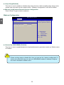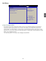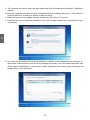
1
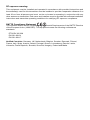
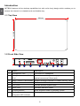
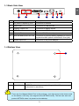
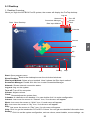
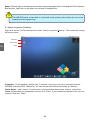
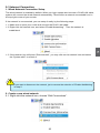
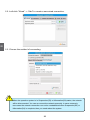
NETBOX User’s Manual
Trademark:
All trademarks are the property of their respective owners.
Version:
User’s Manual V1.2 for NETBOX.
Symbol description:
CA
UT
IO
N
!
Caution : refers to important information that can help you to use NETBOX better, and tells you how to avoid problems.
RoHS
This product has been designed and manufactured in compliance with Directive 2002/95/EC
of the European Parliament and the Council on restriction of the use of certain hazardous substances in electrical and electronic equipment (RoHS Directive) and is deemed to comply with
the maximum concentration values issued by the European Technical Adaptation Committee
(TAC) as shown below:
Substance
Proposed Maximum Concentration
Actual Concentration
Lead (Pb)
0,1%
< 0,1%
Mercury (Hg)
0,1%
< 0,1%
Cadmium (Cd)
0,01%
< 0,01%
Hexavalent Chromium (Cr6+)
0,1%
< 0,1%
Polybrominated biphenyls (PBB)
0,1%
< 0,1%
Polybrominated diphenyl ethers
(PBDE)
0,1%
< 0,1%
Certain components of products as stated above are exempted under the Annex of the RoHS
Directives as noted below:
Examples of exempted components are:
1. Mercury in compact fluorescent lamps not exceeding 5 mg per lamp and in other lamps not
specifically mentioned in the Annex of RoHS Directive.
2. Lead in glass of cathode ray tubes, electronic components, fluorescent tubes, and electronic
ceramic parts (e.g. piezoelectronic devices).
3.
Lead in high temperature type solders (i.e. lead-based alloys containing 85% by weight or
more lead).
4.
Lead as an allotting element in steel containing up to 0.35% lead by weight, aluminium
containing up to 0.4% lead by weight and as a cooper alloy containing up to 4% lead by weight.
CAUTION: RISK OF EXPLOSION IF BATTERY IS REPLACED BY AN INCORRECT
TYPE DISPOSE OF USED BATTERIES ACCORDING TO THE INSTRUCTIONS
© All rights reserved.
All trade names are registered trademarks of respective manufacturers listed.
All images are for reference only, please refer to the physical product for specific features.
Statement:
This device complies with part 15 of the FCC Rules. Operation is subject to the following two
conditions: (1) This device may not cause harmful interference, and (2) this device must accept any interference received, including interference that may cause undesired operation.
Warning:
FEDERAL COMMUNICATIONS COMMISSION INTERFERENCE STATEMENT
This equipment has been tested and found to comply with the limits for a Class B digital
device, pursuant to part 15 of the FCC Rules. These limits are designed to provide reasonable
protection against harmful interference in a residential installation. This equipment generates,
uses and can radiate radio frequency energy and, if not installed and used in accordance with
the instructions, may cause harmful interference to radio communications. However, there is
no guarantee that interference will not occur in a particular installation. If this equipment does
cause harmful interference to radio or television reception, which can be determined by turning the equipment off and on, the user is encouraged to try to correct the interference by one
or more of the following measures:
▪ Reorient or relocate the receiving antenna.
▪ Increase the separation between the equipment and receiver.
▪ Connect the equipment into an outlet on a circuit different from that to which the receiver
is connected.
▪ Consult the dealer or an experienced radio/ TV technician for help.
Caution:
Any changes or modifications not expressly approved by the grantee of this device could
void the user’s authority to operate the equipment.
CE Conformity for European Countries
The device complies with the EMC Directive 2004/108/EC and Low Voltage Directive
2006/95/EC.
Following information is only for EU-member states:
The mark shown to the right is in compliance with the Waste Electrical and
Electronic Equipment Directive 2002/96/EC (WEEE).
The mark indicates the requirement NOT to dispose the equipment as unsorted
municipal waste, but use the return and collection systems according to local law.
If the batteries, accumulators and button cells included with this equipment, display
the chemical symbol Hg, Cd, or Pb, then it means that the battery has a heavy metal
content of more than 0.0005% Mercury or more than, 0.002% Cadmium, or more than 0.004%
Lead.
RF exposure warning:
This equipment must be installed and operated in accordance with provided instructions and
the antenna(s) used for this transmitter must be installed to provide a separation distance of at
least 20 cm from all persons and must not be co-located or operating in conjunction with any
other antenna or transmitter. End-users and installers must be provide with antenna installation
instructions and transmitter operating conditions for satisfying RF exposure compliance.
R&TTE Compliance Statement
This wireless module device complies with the Essential Requirements of the R&TTE Directive
of the European Union (1999/5/EC). This equipment meets the following conformance
standards:
ETSI EN 300 328
EN 301 489-01
EN 301 489-17
Notified Countries: Germany, UK, Netherlands, Belgium, Sweden, Denmark, Finland,
France, Italy, Spain, Austria, Ireland, Portugal, Greece, Luxembourg, Estonia, Latvia,
Lithuania, Czech Republic, Slovakia, Slovenia, Hungary, Poland and Malta.
CA
UT
IO
N
Safety Notice :
!
Before using this product, please read the below safety notice carefully,
this will help to extend the product’s lifecycle, and work normally.
■ When NETBOX is working, please make sure its ventilation system is
working.
■ The power adapter is dissipating heat during normal use, please be sure
not to cover it and keep it away from your body to prevent discomfort or
injury by heat exposure.
■ Please use the power adapter that comes with the product’s package,
wrong power adapter may damage your device.
■ Make sure all the peripherals are properly connected before using NETBOX.
■ This product should only be used in an environment with ambient temperatures between 0◦C and 40◦C.
■ To reduce the risk of fire, use only No. 26 AWG or larger UL listed or
CSA certified telecommunication line cord.
■ Always shut down the computer before installing or uninstalling the peripheral which does not support hot plug.
■ Disconnect all peripherals before servicing or disassembling this equipment.
■ Please do not disassemble this product by yourself, any disassembly
not approved by the original manufacturer may result in malfunction, and
void warranty.
■ Risk of explosion if battery is replaced by an incorrect type, please dispose of used batteries according to the instructions.
Table of Contents
Chapter 1 Introducing the NETBOX
Top View....................................................................................................2
Front Side View.........................................................................................2
Back Side View.........................................................................................3
Bottom View..............................................................................................3
LED Indicator Introduction.........................................................................4
Chapter 2 Placing and connecting the NETBOX
Placement of NETBOX
On the Desk..........................................................................................6
On the Display Back..............................................................................6
Connection of NETBOX
Connect the Antenna.............................................................................8
Connect the Monitor..............................................................................8
Connect the USB Devices.....................................................................8
Connect the Network Cable..................................................................9
Connect the Power Cord.......................................................................9
Chapter 3 BIOS Setup
Main Menu............................................................................................... 11
Advanced Menu...................................................................................... 11
Exit Menu................................................................................................13
Chapter 4 Install Windows 7 in NETBOX
Install Windows 7....................................................................................15
Install Drivers in Windows 7....................................................................19
Chapter 5 FoxOS Introduction
First Boot.................................................................................................21
Desktop...................................................................................................23
Internet Connection.................................................................................25
“Help” Introduction...................................................................................29
Recover FoxOS 3.0 Home......................................................................30
The NETBOX is a compact and easy to use desktop. It features all
the desktop capabilities but with a slim body design which enables
your to browse the internet in a relax and comfortable way.
This chapter introduces NETBOX’s outlook :
■
Top View
■
Front Side View
■
Back Side View
■
Bottom View
■
LED Indicator Introduction
1
Introduction
NETBOX features all the desktop capabilities but with a slim body design which enables you to
browse the internet in a relaxable and comfortable way.
1-1 Top View
190mm
135mm
1-2 Front Side View
25mm
1
2
3
4
LLS_LED1
5
LLS_LED5
6
7
8
No. Name
Description
1
Headphone Port
Connects to a headphone
2
Microphone In and S/PDIF In
Port
Connects to a microphone or playback devices with
optical connectors(3.5mm jack)
3
Multi-Function Card Reader
Support SD/SDHC/MS/MS Pro/MMC memory cards
4
USB Ports
Connect to USB devices
5
LLS_LED
Indicate different system state
6
HDD_LED
Indicates hard disk states
7
Suspend Button
Enter suspend mode in operating system
8
Power Button with
Integrated LED Indicator
Turning the power on/off, Indicates system states
1-3 Back Side View
1
1
2
3
4
5
6
7
No. Name
Description
1
RF(Radio Frequency) Port
Connects to antenna
2
USB Ports
Connects to USB devices
3
Display Output Port
Connects to display device
4
HDMI Port
Connects to HDMI audio and video
5
Network Port
Standard RJ-45 network port
6
Line Out and S/PDIF Out Port
Connects to powered analog speakers or recording devices with optical connectors(3.5mm jack)
7
Power Input Port
Connects to the power adapter
1-4 Bottom View
1
No.
1
CA
UT
IO
N
!
Name
Description
Sheet Metal
NETDVD(optional accessary) or Magnet-Metal-Feet can magnetize them to seat firmly
There are four Magnet-Metal-Feet in the package. Just align them to the sheet metal
on the bottom, then they can magnetize the NETBOX easily. The feet can seat and
protect NETBOX when it is placed on the tabletop.
1
1-5 LED Indicator Introduction
CA
UT
IO
N
!
Indication
Power_
LED
HDD_
LED
LLS_
LED1
LLS_
LED2
LLS_
LED3
LLS_
LED4
LLS_
LED5
S0(Working Mode)
Green
-
Off
Off
Off
Off
Off
S1(Power-Saving Mode)
Green
Off
Off
Off
Off
Off
Off
S3(Standby Mode)
Red
Off
Off
Off
Off
Off
Off
S4(Hibernation Mode)
&S5(System Power Off Mode)
Red
Off
Off
Off
Off
Off
Off
CPU
Initialization Error
-
-
Blue,
Blink
-
-
-
-
DRAM Error
-
-
-
Blue,
Blink
-
-
-
BIOS Boot Block Fail
-
-
-
-
-
Blue,
Blink
-
BIOS
Checksum Error
-
-
-
-
-
-
Blue,
Blink
CMOS Cleared
Red,
Blink
-
-
-
-
-
-
HDD R/W Data
-
Red
-
-
-
-
-
The LLS_LEDs status in this table only show BIOS error message.
In this chapter, the placement and the connection of some necessary peripherals will be introduced.
This chapter includes the following information:
■
Placement of NETBOX
■
Connection of NETBOX
2-1 Placement of NETBOX
1. On the Desk
1. You can install your NETBOX in the mount like the right image.
2
2. If there is enough space on your desk, you can simply put your NETBOX on the tabletop as shown below.
2. On the Display Back
CA
UT
IO
N
This is the best space-saving way.
1. Use four screws to fasten the bracket onto the display back.
!
To install this bracket, your display must follow VESA75/VESA100 standard. The two
groups of holes on your dispaly have different space between, and they help you
easily fasten the bracket onto your display.
2. Fit the NETBOX into the bracket with power button locating at the top for easy touch.
2
2
1
3. After that, you can connect the antenna to your NETBOX.
CA
UT
IO
N
!
Remove the antenna and lift up the NETBOX straightly to take it out.
2-2 Connection of NETBOX
1. Connect the Antenna
2
Connect the antenna to the RF port of the NETBOX. You can fold the antenna and rotate it in different angle as you want.
1
2
2. Connect the Monitor
Connect a monitor to the NETBOX through DVI connector.
3. Connect the USB Devices
Connect USB devices to the USB ports of the NETBOX, for example, mouse and keyboard.
4. Connect the Network Cable
Connect LAN cable to the RJ-45 port, with the other end connected to a hub or switch.
2
Hub
or
Switch
5. Connect the Power Cord
Connect the power adapter to the power input port of the NETBOX, and push the power button to
start it.
1
Outlet
3
CA
UT
IO
N
2
!
The power adapter is dissipating heat during normal use, please make sure not to
cover it and keep it away from your body to prevent discomfort or injury from heat
exposure.
This chapter provides a description of the BIOS setup utility. The
BIOS setup menus and available selections may vary from those
of your product. For specific information on the BIOS for your
product, please visit our Website.
The BIOS setup utility provides a built-in Setup program, which
allows the user to modify the basic system configuration and hardware parameters. The modified data will be stored in a batterybacked CMOS, so that data will be retained even when the power
is turned off. In general, the information saved in the CMOS RAM
will not need to be changed unless there is a configuration change
in the system, such as a hard drive replacement or when a device
is added. It is possible for the CMOS battery to fail, which will
cause data loss in the CMOS only. If this happens you will need to
reconfigure your BIOS settings.
This chapter includes the following information:
■
Main Menu
■
Advanced Menu
■
Exit Menu
Main Menu
The BIOS Setup is accessed by pressing the <Del> button after the Power-On Self-Test (POST)
memory test begins and before the operating system boot begins. Once you enter the BIOS Setup Utility, the Main Menu will appear on the screen. The Main Menu provides System Overview
information and allows you to set the System Time and Date. Use the “←” and “→” cursor keys to
navigate between menu screens.
Main
Advanced
Chipset
BIOS SETUP UTILITY
Boot
Security
Exit
Use [ENTER] ,[TAB],or [SHIFT-
TAB] to select a field.
Use [+] or [-] to
configure system Date.
← Select Screen
↑↓
Select Item
+/Change Field
Tab Select Field
F1
General Help
F10 Save and Exit
ESC Exit
v02.61 (C) Copyright 1985-2006, American Megatrends, Inc.
Advanced Menu
Main
Advanced
Chipset
BIOS SETUP UTILITY
Boot Security Exit
Advanced Settings When entering deep sleep
mode, system can only
wake up from power button
Suspend mode
[S3 (STR)]
(wake up configuration will
Legacy USB Support
[Enabled]
be hidden).
Restore on AC Power Loss
[Last State]
Deep Sleep
[Enabled]
► Onboard Device Configuration
← Select Screen
↑↓
Select Item
+/Change Option
F1
General Help
F10 Save and Exit
ESC Exit
v02.61 (C) Copyright 1985-2006, American Megatrends, Inc.
11
3
Main Information
Market Name : JTX-N
Model Name : JTX-N
System Date
[Thu 08/06/2009]
System Time
[09:44:21]
► SATA:
[Hard Disk]
► System Information
► Deep Sleep[Enabled]
This item is used to enable or disable deep sleep function. When enabling deep sleep mode, system can only wake up from power button. “Wakeup Configuration” item will be hidden.
►Wakeup Configuration/Onboard Device Configuration
Press <Enter> to go to relative submenu.
Wakeup Configuration
BIOS SETUP UTILITY
Advanced
3
Wakeup Configuration
Resume on PCIE
Resume By RTC Alarm Resume By USB KB/MS [Disabled]
[Disabled]
[Enabled]
Disable/Enable the keyboard/ mouse to generate a wake up.
← Select Screen
↑↓
Select Item
+/Change Option
F1
General Help
F10 Save and Exit
ESC Exit
v02.61 (C) Copyright 1985-2006, American Megatrends, Inc.
► Resume By USB KB/MS [Enabled]
This item is used to enable/disable the keyboard/mouse to generate a wake up. Defalut value
CA
UT
IO
N
is Enabled.
!
Please set deep sleep to disable first, then you can see the “wakeup configuration” in
setup menu. After this step, you can see USB KB/MS enabled in wakeup configuration memu. Enabled is default value.
12
Exit Menu
Main
Advanced
Chipset
BIOS SETUP UTILITY
Boot
Security Exit
Exit Options Save Changes and Exit Discard Chages and Exit Discard Changes
Load Optimal Defaults
Exit system setup after saving the changes.
F10 key can be used
for this operation.
3
← Select Screen
↑↓
Select Item
Enter Go to Sub Screen
F1
General Help
F10 Save and Exit
ESC Exit
v02.61 (C) Copyright 1985-2006, American Megatrends, Inc.
► Save Changes and Exit
Exit system setup after saving the changes. Once you are finished making your selections,
choose this option from the Exit menu to ensure the values you selected are saved to the
CMOS RAM. The CMOS RAM is sustained by an onboard backup battery and stays on even
when the PC is turned off. When you select this option, a confirmation window appears. Select
[OK] to save changes and exit.
You can also press <F10> key to save change and exit BIOS.
13
This chapter introduces the Windows installation :
■
Install Windows 7
■
Install Drivers in Windows 7
Make sure you have these ready :
1. NETDVD. (It is an optional accessory. If there is no NETDVD in this package, you need other
purchase an external USB DVD-ROM drive.)
2. NETBOX driver CD. (In this package)
3. Windows 7 Install CD. (Other purchase)
Before we continue :
■
■
Your NETBOX power is off.
Connect the NETDVD or USB DVD-ROM drive to one USB port of NETBOX and power it on.
4
4-1 Install Windows 7
1. Push power on button to turn on your computer, then press <Del> key to enter BIOS Setup.
2. Put the Windows 7 Install CD into the NETDVD or USB DVD-ROM drive.
3. Select and go to the “Boot” menu, enter “Boot Device Priority”, set the “1st Boot Device” to
“USB: Optical DVD RW”, press <F10> key to save change and exit BIOS.
BIOS SETUP UTILITY
Boot
Boot Device Priority
1st Boot Device [USB:Optical DVD RW]
2nd Boot Device [SATA:3M-FUJITSU MH]
3rd Boot Device
[USB:Generic STORAG]
Specifies the boot
sequence from the
availabe devices.
A device enclosed in
parenthesis has been
disabled in the
corresponding type menu.
← Select Screen
↑↓
Select Item
+/Change Option
F1
General Help
F10 Save and Exit
ESC Exit
v02.61 (C) Copyright 1985-2006, American Megatrends, Inc.
15
4. The computer will reboot, and it will start loading the files for installing the Windows 7 Operating
System.
5. After the computer reboots it will start loading the files for installing Windows 7. Click “Next” to
continue and click “Install now” button to start the setup.
4
6. When the license terms appear choose accept and click “Next” to continue.
7. It will then ask you to select the installation type. Click “Custom (advanced)” to install a new copy
of Windows.
8. The setup will the display the hard disk partitions (160GB, in this example) of your system. If
there were other systems (such as Linux) installed previously, you need select them and click
“Drive options (advanced)” to delete them. When all partitions are clean, setup will display the
biggest size of your hard drive.
16
9. In the hard disk size screen, you can click the “new” button to create partitions as you need. In
this example we are creating a 70GB partition to install Windows. Make your modifications and
click “Apply”.
4
To ensure that all Windows features work correctly, Windows might create additional
partitions for system files. So you will see a 100MB partition reserved by system after you
create a partition. Select the 70GB partition and click “Next” to continue.
17
4
10. The setup program will then start to install Windows 7 on your hard disk. During the installation, your computer will restart several times.
11. When the installation is complete, setup will prepare your computer for it’s first use. You can
then follow the steps to select system settings, create an account, set a password...etc, until
the whole process is complete.
18
4-2 Install Drivers in Windows 7
1. When the Windows 7 is completely installed, you have to install the necessary drivers before
using the NETBOX. Take out the Windows 7 Install CD from the USB DVD-ROM drive, and put
the NETBOX driver CD inside.
2. Waiting for a few seconds, the main menu will be displayed on the screen.
4
3. Use these options to install all the drivers for your system. You must click "NVIDIA Chipset Driver"
to install it first. After that, you can click "One Click Setup" to install all the other drivers, or you
can click on each individual driver to install it manually.
4. After all the drivers are installed, you need to restart your NETBOX, then you can start using it.
19
FoxOS is a newly developed Linux Operating System. If it was
purchased and pre-installed by factory, the first time you start
your computer, the computer will automatically launch "First
Boot". This chapter will guide you through the setup and registration processes. Besides this, we will introduce the desktop
features, Internet Connection and operation system recovery
method.
This chapter includes the following information:
■
First Boot
■
Desktop
■
Internet Connection
■
“Help” Introduction
■
Recover FoxOS 3.0 Home
5-1 First Boot
For the first time, when you start NETBOX with FoxOS, the computer will automatically launch "First
Boot". This section will guide you through the setup and registration processes. Please follow below
steps to complete the setup.
1. Select the language and click “Forward” to continue.
5
2. Browse the [Welcome] page and click “Forward” to the next, then select “Yes” and click “Forward”.
3. Select a keyboard, and click “Forward” to continue.
21
5
4. Select Date and Time, then click “Forward” to continue.
5. Input the “Username” and “Password”, then click “Finish” to complete the setup. This “Password”
will be used as the initial root password.
6. The system will come out the login screen, select the user and input the password to login.
22
5-2 Desktop
1. Desktop Overview
When you login the NETBOX FoxOS system, the screen will display the FoxTop desktop:
Log-out
Start Show Desktop
Network
Turn Off
Screenlets Manager
Volume
Clock
iBus Input Method
Calendar
Internet
My
Play
Setting
Wbar
Help
Start: Open program menu.
Show Desktop: Back to the desktop/recover the minimized windows.
iBus Input Method: Select a input method. Here it shows the iBus input method.
Screenlets Manager: Double click this icon to start Screenlets Manager.
Network: Shows network connection status.
Log-out: Log out the system.
Turn-off: Turn off the computer.
Volume: Adjusts volume.
Clock: Shows/adjusts the system time.
Calendar: A calendar on the desktop. You can double click it to make configuration.
Internet: Just move the mouse to “Internet” Icon, it’s sub-menu will appear.
Work: Just move the mouse to “Work” Icon, it’s sub-menu will appear.
My: Just move the mouse to “My” Icon, it’s sub-menu will appear.
Play: Just move the mouse to “Play” Icon, it’s sub-menu will appear.
Help: Click it to get the introduction of FoxOS 3.0 Home. You can get more detailed information here.
Setting: Click it to set the system configuration, such as volume, smart installer, mouse settings...etc.
23
5
Work
CA
UT
IO
N
Wbar: Click the logo on the Wbar to launch the corresponding application, including the Firefox browser.
Besides this, right click on the Wbar can refresh it’s background.
!
If a USB DVD drive or hard disk is connected in the system, there will be an icon on the
desktop and the system tray.
2. Switch to gnome Desktop
Right click on the FoxTop desktop and select “Switch to gnome Desktop”. The screen will change
as below picture.
Computer
5
test’s Home
Trash
Computer: On the desktop, double-click "Computer" will bring out a list of devices inside the
NETBOX (including HDD, USB drive). You can access each device individually by clicking it.
Test’s Home: "test’s Home" is used to store user's personal documents, video or music files.
Trash: Deleted files are temporarily stored in the “Trash”. If you mistakenly deleted a file, you can
restore it from the “Trash”.
24
5-3 Internet Connection
1. Wired Network Connection Setup
The wired network is enabled by default. When you login system and connect a RJ-45 LAN cable,
system will connect the wired network automatically. There will be a network connectable icon in
the top right corner of your screen.
If the network is unconnected, you can setup it easily by the following steps:
1.1. Make sure to open your router and connect the RJ-45 LAN cable.
1.2. Right-click the network icon, and select “Enable Networking”. Then the network is established.
5
CA
UT
IO
N
1.3. If the network icon still show “Disconnected”, you may click on the network icon and select the “System eth0” to refresh it. !
If you want to disconnect the network, just to remove the selection of “Enable NetWorking”
in step 2.
2. Create a new wired network
2.1. Right-click the network icon, choose “Edit Connections”.
25
5
2.2. Left-click “Wired” -> ”Add” to create a new wired connection.
CA
UT
IO
N
2.3. Choose the method of connecting.
!
When the operation system is in Suspension(S3) or Hibernation(S4) status, the network
will be disconnected. You can re-connect the network manually. In some extremely
rare cases the network connection can not be reestablished when Suspension(S3) or
Hibernation(S4) is complete, then you need reboot the system.
26
3. Wireless Network Connection Setup
The wireless network is enabled by default. If your space is covered by the wireless network signal,
your NETBOX will search the available wireless networks automatically, then click the network icon
to connect it manually. Usually, it needs you to input a password to connect the wireless network.
You can get the password from telecommunication business hall.
CA
UT
IO
N
!
Remove the selection of “Enable NetWorking” will disconnect with the wireless network.
4. Connect to hidden wireless network
4.1. Right-click the network icon and select “Connect to Hidden Wireless Network”.
27
5
If your wireless network is disabled, you can enable it easily by the following step:
Right click the network icon and select “Enable Wireless” to connect the wireless network.
4.2. Input the “Network Name” and select “Wireless security”, then click “Connect”.
5. DSL Connection Setup
5
5.1. Right-click the network icon, and choose “Edit Connect” -> ”DSL” -> Add”. Input User name and Password. Click “Apply” to create a DSL connection.
5.2. Click the ”DSL connection 1” to connect to the network.
28
5-4 “Help” Introduction
The "Help" icon on the desktop provides you with detailed and systemic introduction about FoxOS
3.0 home.
5
Just click the "Help" icon on the desktop, system will open a PDF file.
In this file, we introduce almost all the configurations and applications come with the FoxOS 3.0
Home. It includes how to install, remove or recover the operating system. Besides this, it also
contains detail introductions about the "Main Desktop", "Setting", "Work", "Internet", "play", "My"
etc.
29
5-5 Recover FoxOS 3.0 Home
This section will introduce you two ways to recover the FoxOS 3.0 Home. One is to recover from
a recovery disk (USB or DVD), another is to recover from the hard disk.
1. Recover system from a USB or DVD disk
First we need to create a recovery USB or DVD, then use it to recover the FoxOS 3.0 system.
In fact, there is a DVD disk in the package. Except installing drivers, it also can be used to recover FoxOS 3.0 Home directly.
1.1. Create a Recovery USB or DVD disk
5
1.1.1. Select "Start Menu"-> "System tools"-> "Recovery Manager" to start the "FoxOS Recovery USB&DVD Maker" and click "Next" to start.
1.1.2. Select the disk type you want to create and click "Next" to continue.
30
CA
UT
IO
N
1.1.3. Connect the USB flash disk to your computer or insert a DVD disk into the DVD driver. When the system recognize the device, select it and click "Next". Then it starts to copy system files, modify documents and create a USB or DVD recovery disk. This process will take a long time, please wait patiently. (The following picture uses DVD as the example.)
!
■
■
■
The USB flash disk or the DVD disk will be formatted. Make sure to make a copy for it before creating the recovery disk.
The USB flash disk must be "vfat" format and no less than 3GB.
The DVD must be "DVD-R/DVD-RW" format and no less than 3GB.
5
During making a recovery DVD, system will create an iso file first. When the file is created, click "Next"
to continue. Creating a recovery USB is without this step.
1.1.4. When the recovery USB or DVD disk is created, system will remind you. Click “OK” to finish the process. Now you have got a recovery USB or DVD disk.
31
1.2. System Recovery from the USB or DVD disk
1.2.1. Power on the computer, connect the recovery USB or insert the recovery DVD into DVD driver. When the prompt message appears on the screen, press “F11” to enter Boot Menu and set USB(Removable Device) or DVD as the first boot device. Computer will continue to boot up.
CA
UT
IO
N
5
1.2.2. When the following picture shows, select "Install and make recovery partition" and click “Next”
to install system and make a recovery partition in the hard disk. This recovery partition will
provide “ A key to Resume” function which is very convenient for users. If you select "Install system only", there will be no “ A key to Resume” function.
!
■ Usually the recovery partition will occupy about 5GB of the hard disk.
1.2.3. A warning message will show as below. Click "Next" to continue.
32
1.2.4. It starts to format hard disk and install system.
5
1.2.5. When the installation is complete, click "Reboot" to restart the system.
33
2. System Recovery from the Hard Disk
If FoxOS 3.0 Home was purchased and pre-installed by factory, they should have created a
recovery partition in the hard disk. Now we can use the hard disk to recover the system.
5
1. Start the system, during the screen prompt, press any key to enter Grub interface. The picture will show as below:
2. Select "FoxOS recovery" item and press "Enter". A warning message will show as below:
3. Click "Next". System warns the root partition(hd0, 0) will be formatted.
34
4. Click "Next" to format partition(hd0,0) and recover system from hard disk. The picture will show as below:
5
5. When the installation is complete, click "Reboot" to restart the system.
35