1
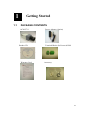
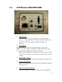
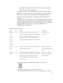
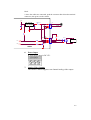
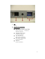
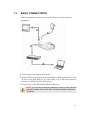
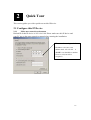
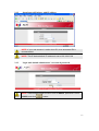
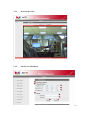
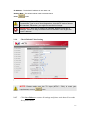
IP Box Camera
ACM-5711
Ver. 080131
Quick Installation Guide
10
1.1
Getting Started
PACKAGE CONTENTS
ACM-5711
Product CD
Warranty Card
Power Adaptor (Option)
Terminal Blocks for Power & DI/O
Accessory
0-1
1.2
PHYSICAL DESCRIPTION
1.
Ethernet Port
The IP device connects to the Ethernet via a standard RJ45
connector. Supporting NWAY, this IP device can auto detect the
speed of local network segment (10Base-T/100Base-TX
Ethernet).
2. Reset Button
Step 1: Switch off IP device by disconnecting the power cable
Step 2: Press and continue to hold the Reset Button. Reconnect the
power cable while continuing to hold the reset button.
Step 3: Keep holding the reset button depressed around 6 seconds,
release the reset button. The unit will start up with factory default
settings.
3.
Audio Input / Output
The IP device supports audio input and output with earphone jack
4.
Action LED Indicator
The LED will light up after IP camera has successfully completed
the boot process
5.
The I/O Terminal Connector
Used in applications for e.g. motion detection, event triggering,
0-2
time lapse recording, alarm notifications, etc., the I/O terminal
connector provides the interface to:
•1 transistor output - For connecting external devices such as relays
and LED:s. Connected devices can be activated by Output buttons on
the Live View page or by an Event Type. The output will show as
active (in Event Configuration > Port Status) if the alarm device is
activated.
•1 digital input - An alarm input for connecting devices that can toggle
between an open and closed circuit, for example: PIRs, door/window
contacts, glass break detectors, etc. When a signal is received the state
changes and the input becomes active (shown under Event
Configuration > Port Status).
•Auxiliary power and GND
GND
Pin 1
Ground
Description
Auxiliary
Pin 2
Electrically connected in parallel with the con-
Voltage: 12V DC,
DC
nector for the power supply, this pin provides an
Max: 1.2W
Power
auxiliary connector for mains power to the unit.
input
This pin can also be used to power auxiliary
(not to
equipment, with a maximum current of 100mA.
power
this
camera)
Digital
Pin 3
Input
Connect to GND to activate, or leave floating (or
Must not be exposed to
unconnected) to deactivate.
voltages greater than 30V
DC.
Transistor
Output
Pin 4
Uses an open-collector NPN transistor with the
Max load = <100mA
emitter connected to the GND pin. If used with an
Max voltage = 24V DC
external relay, a diode must be connected in
(to the transistor)
parallel with the load, for protection against
voltage transients.
The I/O terminal pins are numbered left to right, as shown below.
Connect input/output devices to the camera as follows:
1. Attach the cables for the device securely to the supplied green connector
0-3
block.
2. Once the cables are connected, push the connector block into the terminal
connector (also green) on the camera.
3.3V
FUSE 1A
1
+
DC TO DC
2
CONVERTER
3
-
POWER INPUT
EARTH GND
GND
DC POWER
DI
DI
DO
SW
1
RELAY
2
3
DIODE
DEVICE
4
NPN
DO
CAMERA
6.
Power Input
If your power input is DC12V.
7.
Analog Video Output
The IP Box Camera supports one channel analog video output.
0-4
8.
Iris
DC Iris
9. Video DC Level Adjustment
10. CCD Functions
z Auto Electronic Shutter Speed Mode
AES On: 1/50 (60) sec. ~ 1/120,000 sec;
AES Off: 1/50 (60) sec.
z
Automatic Gain Control
ON/OFF (Switchable)
z
Auto White Balance
AWB / Push Lock WB Mode
z
Back Light Compensation
ON/OFF (Switchable)
z
Sense UP
ON/OFF (Switchable)
0-5
1.3
BASIC CONNECTIONS
Follow the procedures below to connect the IP device to the respective
apparatuses.
1. Connect the power adaptor to IP device
2. Connect IP device’s ethernet port to an Ethernet (RJ45 connectors). If your
IP device has PoE built-in, you can regard it as a PD and connect it
directly to a PSE device like PoE switch.
3. Connect a PC to the Ethernet hub (RJ45 connectors)
1
NOTE: You may find a support package for help you getting familiar
with PoE. Please visit our web site, and get the support document
TS-00040.
0-1
21
Quick Tour
This section guides you with a quick tour on this IP device.
2.1 Configure this IP Device
2.1.1
Make sure network environment
Default IP of this IP device is 192.168.0.100. Please make sure this IP device and
your PC are on the same network segment before running the installation.
Please set the settings as below.
IP address: 192.168. 0.xxx
Subnet mask: 255.255.255. 0
(NOTE: xxx should be a number
from 1 to 254, but 100 is
excepted.)
1-2
2.1.2
Open Internal Explorer with IP address
NOTE: If your web browser is earlier than IE6, then download IE6 is
recommended.
NOTE: This IP device default IP address is set to 192.168.0.100
2.1.3
Login with default administrator’s account & password
NOTE: Default administrator account is set to Admin, password is set to
123456, and click
button.
1-3
2.1.4
Preview the video
2.1.5
Set the new IP address
1-4
*IP Address : The default IP address is 192.168.0.100.
*Subnet Mask : The default subnet mask is 255.255.255.0
*Click
button
NOTE: In your Client PC, please make sure the setting of Network
Connections Type is set to Auto Negotation, since this IP device follows
MII standard. Otherwise, you might not see the live image.
IMPORTANT: After the IP address is changed, please record this IP
address. There’s no way to connect to the IP device if user forgets the
new IP address.
2.1.6
Check Default Video Setting
NOTE: Please make sure the TV Input (NTSC / PAL) is meet your
requirement, and click
2.1.7
button.
Click Save Reboot to restore all settings and please wait about 30 seconds
for system reboot.
1-5