1
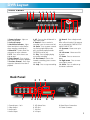
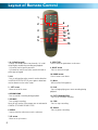
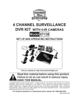
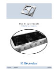
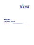
™
Advanced security made easy
plug&playsecurity
™
DVR8-2500™
8 Channel H.264 Digital Video Recorder
Operating Instructions
Operating Instructions
SW342-2DE
www.swannsecurity.com
SR342-2DE-60010-230709
Before You Begin
FCC Verification:
NOTE: This equipment has been tested and found to comply with the limits for
Class B digital device, pursuant to part 15 of the FCC Rules. These limits are designed to provide reasonable protection against harmful interference in a residential installation. This equipment generates, uses and can radiate radio frequency
energy and, if not installed and used in accordance with the instructions, may
cause harmful interference to radio or television reception, which can be determined by turning the equipment off and on, the user is encouraged to try to
correct the interference by one or more of the following measures:
· Reorient or relocate the receiving antenna
· Increase the separation between the equipment and the receiver
· Connect the equipment into an outlet on a circuit different from that to which
the receiver is connected
· Consult the dealer or an experienced radio/TV technician for help
These devices comply with part 15 of the FCC Rules. Operation is subject to the
following two conditions:
(1) These devices may not cause harmful interference, and
(2) These devices must accept any interference received, including interference
that may cause undesired operation.
IMPORTANT NOTE: Prohibition against eavesdropping
Except for the operations of law enforcement officers conducted under lawful
authority, no person shall use, either directly or indirectly, a device operated pursuant to the provisions of this Part for the purpose of overhearing or recording the
private conversations of others unless such use is authorized by all of the parties
engaging in the conversation.
WARNING: Modifications not approved by the party responsible for compliance
could void user’s authority to operate the equipment.
IMPORTANT SAFETY INSTRUCTIONS:
· Make sure product is fixed correctly and stable if fastened in place
· Do not operate if wires and terminals are exposed
· Do not cover vents on the side or back of the DVR and allow adequate space for
ventilation
2
DEFAULT PASSWORD INFORMATION
· This DVR is password protected.
· To unlock the DVR for the first time, the default password is “123456”.
· To ensure your ongoing privacy, we strongly recommend changing the password
as soon as possible. Choose something that you’ll remember, but that others
would be unlikely to guess.
· If you do manage to lock yourself out of the DVR, you’ll need to contact us at the
Swann Technical Support Telephone Helpdesk - the number is on the back cover.
Contents
Before you Begin
2
Table of Contents
Package Contents
3
4
DVR Layout
Layout of Remote Control
Connecting Cameras to the DVR
Starting the DVR
5
6
7
8
Navigating the Menus
The Main Menu
Hard Drive Setup
Setting the Time
Configuring the Camera Display
9
9
10
11
12
Recording
Search and Playback
14
17
Backing up Footage
Motion Detection
Password Control
Language
System Menu
PTZ
19
19
21
21
22
23
Installing the DVR Software
Configuring Active X
Network Setup
D9 Viewer Software
26
29
30
31
About IP Addresses
Port Forwarding
38
38
Installing/Changing the Hard Drive
39
Troubleshooting
Technical Specifications
40
41
Warranty Information
43
Technical Support
Back Cover
3
Package Contents
DVR4-2500™ Unit
Remote Control
Operating Instructions
Easy Setup Guide
Power Adapter with Cable
Software CD
Network cable
USB cable
RCA Video Cable
RCA to BNC adapters X 4
Security Stickers (4 Pack)
If you are missing any of the components above, contact Swann Communications
for assistance.
4
DVR Layout
Front Panel
1 2 3
4
5
6
7
8
9 10 11 12 13 14 15 16 17 18 19
1. Power Indicator - Lights on
when DVR powered
2. Infra red sensor
3. Hard drive indicator - Lights
when hard drive is active (flashes
when recording, searching etc.)
4. Menu/ESC - Used to enter the
main menu or exit a sub menu.
5. PTZ - Press in live view to see
pop up menu.
6. Next Channel - Press to go to
next channel in live view or playback
7. Previous Channel - Press to go
to previous channel in live view or
playback
Back Panel
1
1.Channel Inputs 1 to 8
2. Video Output
3. Audio Input
4. Audio Output
8. All - Press to view all channels in
split-screen mode.
9. Rewind - Press to rewind a
recording / press to move cursor left.
10. Pause - Press to pause a recording. During single display mode
press to activate sequence mode.
(AUTOSEQ must be set).
11. Play - Press to begin playing
most recent recording.
12. Fast foward - Press to fast
forward a recording / press to move
cursor right.
13. Stop - Press to stop a recording.
3
7
14. Record - Press to begin recording.
Note: will not function if the cameras
are not activated in CAMERA SETUP
AND RECORD SETUP.
15. Up arrow - Move cursor up in
menus.
16. Left arrow - Move cursor left
in menus.
17. Down - Press to move cursor
down.
18. Right arrow - Press to move
cursor right in menus.
19. Select - Press to select an option/enter a sub menu.
8
2 4 5 6
5. USB Mouse Ports
6. USB Port
7. LAN Port
8. VGA port
9
10
9. Alarm/Sensor Connections
10. Power Connector
5
Layout of Remote Control
1
2
3
4
5
1. 0-9 (digit key pad)
- Buttons 1-4 can be used to view channels 1-4 in individual display mode during recording and playback.
- 0-9 can be used to input a password.
- 0-9 cannot be used for any other numeric field with a
yellow pop up keypad
2. ALL
- Press to activate the entire screen for motion detection
in MOTION DETECTOR SETUP; press again to deactivate
motion detection to the entire screen.
3 - LEFT arrow
- Move cursor left in menus.
4. REWIND/RWD
- Press to rewind a recording during playback.
5. RECORD
- Press to begin recording.
Note: will not function if the cameras are not activated in
CAMERA SETUP AND RECORD SETUP.
6. MENU
- Used to enter the main menu or exit a sub menu.
7. UP arrow
- Move cursor up in menus.
6
6
8
7
9
10
11
12
13
14
15
8. SELECT/SEL
-Press to select an option/enter a sub menu.
9. RIGHT arrow
- Press to move cursor right.
10. DOWN arrow
-Press to move cursor down.
11. Mute
- Will not affect DVR operation.
12. PLAY
- Press to begin playing most recent recording during
playback.
13. FAST FORWARD/FWD
- Press to fast forward a recording.
14. STOP
- Press to stop a recording.
15. Pause
- Press to pause a recording.
Connecting Cameras to the DVR
Cameras and
accessories optional
1
2
3
4
5
6
1. Connect the power and BNC ends of the security camera to an
extension cable.
2. Connect the DC end on the extension cables to the 4 way power splitter plugs.
3. Connect the camera power supply to the other end of the power splitter.
4. Connect the BNC end of the extension cables to the camera connections on the
back of the DVR unit (CH1, CH2, CH3 & CH4)
5. Connect the DVR power supply plug into the power supply socket on the back of
the DVR.
6. Plug in the camera power adapter and the DVR power adapter to mains power
outlets.
7
Starting the DVR
Once you have connected the DVR and switched the power on it will begin to boot up.
During boot up you will see the following screen. The DVR is basically a small, dedicated
computer and thus needs about 45 seconds to boot up. Whilst booting, the DVR will show this
screen:
Once the DVR has booted (up and you have a camera connected to each channel) the DVR will take you
straight to the ‘ALL’ view screen, showing all eight displays (below).
1
8
4
3
1. Displays showing cameras 1 and 3.
3. Displays showing cameras 2 and 4.
2. Audio icon. (in this case audio in active on
camera 1)
4. Date stamp (year:month:day) and Time stamp.
(hour:minutes:seconds)
Navigating the Menus
This DVR comes with a USB mouse and also a remote control, and also has a full compliment of control
buttons on the front panel. So, basically, you have options!
Note: The USB mouse must be attached to the upper USB port!
The mouse functions just like any PC mouse for easy navigation of the menus. In a nutshell, the left mouse
button selects and confirms choices, the right mouse button will take you back towards the main menu.
Most users find that attaching a USB mouse to their DVR is the most convenient way to operate it.
If you prefer to use the remote please read the REMOTE LAYOUT page for instructions on using the remote
before you attempt to set up your DVR. Most buttons on the remote operate in a similar manner to those
on a VCR or DVD player, but due to the specific functionality of the DVR, the function of some buttons may
be obvious. These buttons are also located on the front panel of the DVR.
The Main Menu
To access the main menu push the MENU button on the remote or front panel. Or, if you’re using a mouse,
RIGHT click, and the pop up menu (below) will appear. Click MAIN MENU.
You may find it easier navigating through the DVR menus using the mouse. Simply scroll over the settings
button you want to view and click the LEFT mouse button. Alternatively you can navigate these options
using the UP, DOWN, LEFT & RIGHT buttons on the DVR front panel or the remote control.
The currently selected option
will be magnified and have a
light blue outline.
In this example, the CAMERA
submenu is selected whilst the
mouse cursor is over it.
To confirm a choice, simply left
click or press SELECT whilst
the option is highlighted.
To exit the main menu press the MENU button on the remote or front panel or click the RIGHT mouse
button. This will take you back to the live view.
9
Hard drive Setup
What’s this?
Unlike a VCR which records to a tape, your
DVR records footage to the internal hard drive.
Therefore, it’s an important first step when
configuring your DVR to make sure that the
hard drive (HDD) options are correctly set. Think
of it like inserting a really, really long tape that
you don’t have to rewind.
All the options we’re configuring here you’ll
find in the HDD SETUP submenu.
HDD Status (status of the currently installed hard drive)
If the hard drive is not installed properly you will see a message
saying NO DISK FOUND. Hopefully, though, it will say OK. In LIVE
VIEWING mode, you will see the
icon on the bottom of the
top left display if the hard drive is not installed correctly. If you’re
having problems with this, have a look at the steps for changing
the hard drive on page 39.
The HDD SETUP screen will show you:
TOTAL SPACE - Total size of the hard drive currently installed.
FREE SPACE - Total amount of freespace available on the hard drive currently installed.
USEABLE REC. TIME - Free space currently available in hours.
Additionally, there are some options that need to be configured. Here’s a quick rundown of what’s what.
OVERWRITE
When set to ENABLE the DVR will record over
the oldest files on the hard drive. This is the
default setting, and probably the most useful, as
the DVR will always be able to record events as
they happen. However, it does mean that you’ll
need to get important events off the HDD before
they’re overwritten.
If overwrite is set to DISABLE the DVR will stop
recording once the DVR is full. Whilst you won’t
lose old footage, you run the risk of missing new
events as they happen. Be sure you want to do
this before selecting it.
HDD FORMAT
Formatting the HDD will erase all data (i.e. footage) which is stored on it, and re-create the FAT
(file allocation table).
There are some times when using the format
option is very useful. For example, if the value
displayed in TOTAL SPACE is not correct for the
HDD you’ve installed, or the DVR is displaying
errors when trying to write to the hard drive,
then a format might fix the problem.
Additionally, if you have a USB flash drive
connected to the DVR, you can format that, too.
This will also erase all the data on the drive, but
make the flash drive compatible with the DVR
for backing up footage. To do this, click the USB
FORMAT button and click OK.
10
ALL DATA WILL BE ERASED, ARE YOU
SURE YOU WANT TO FORMAT?
After making changes to the settings press/click the APPLY button.
Setting the Time
Setting the Time & Date
It’s important to set the Time & Date before recording footage. That way, when you
search for events, they’ll be listed in the right order, and display when they were
recorded.
To set the Time and Date:
1. Go to the TIME AND DATE submenu.
2. Highlight the current numeric field, and press select or left click.
3. Use left and right (or the mouse) to select the digit(s) you want to change.
4. Using the up and down arrows/buttons, change the date and time to the
correct values.
5. If using the remote/front panel controls, use the select button to confirm an
entry.
6. Confirm your changes by selecting APPLY.
Selecting Time & Date formats and Time Zone
Choosing the right time & date format and the correct time zone can
save you a lot of time, hassles and confusion later on. So, let’s get them
set up right from the beginning!
TIME FORMAT: Choose between 12 hour time (eg. 3:00 PM) and 24 hour
time (15:00). Both have their advantages and disadvantages, so choose
whichever works for you.
DATE FORMAT: Different countries have different formats for their dates.
Some would represent the 25th of Feburary, 2009 as 02/25/2009, whilst
others would write it as 25/02/2009. Some even start with the year
(2009/02/25). Simply chose the format which is standard in your area.
TIME ZONE: Particularly important if you’re networking your DVR, so it
knows how different the time is where the DVR is and where you might
be accessing it from. Choose the time zone of your particular locality.
Daylight Savings Time
Setting the Daylight Savings settings correctly will ensure that, when daylight savings
commences or ends in your locality that the DVR will automatically update its time settings
to stay synchronised with the actual time.
Enable or disable daylight savings time (DST) by selecting ON or OFF from the DST dropdown menu.
Once you’ve turned DST, you’ll need to set the appropriate
DST MODE from the additional drop-down menu which will
appear.
Select the appropriate option. If you choose CUSTOM, you will
be asked to configure the DST MODE to suit the needs and
requirements of your locality (see next page for details).
After making changes to the settings press/click the APPLY button.
11
Setting the Time (continued)
Configuring custom DST MODE
As the standards for daylight savings differ from country to country, and often state to state, you might need to manually tell the
DVR exactly when it commences and ends in your locality.
To do this, we need to configure the settings in the DST MODE
CUSTOM submenu.
First, select the appropriate week from the drop-down menu which
lists the 1ST WEEK, 2ND WEEK (and so on) that DST commecnces
in your region. Then, select the appropriate month from the dropdown menu listing months.
Repeat these steps for the week and month that daylight savings ends. Once configured, your DVR will automatically
adjust the time settings when daylight savings begins and ends without you having to change anything.
Configuring the Camera Display
In the DISPLAY SETUP screen you can name each channel, select the position of each channel name, adjust the color
set up for each channel, switch the channels on & off in live view, display time in live vew & recording and set time for
auto sequence.
Naming Channels
If the names CH1,CH2 and so on seem a little dull, then feel
free to rename them!
To do so, select the CHANNEL NAME option from the menu.
Use the mouse or arrow keys to select, letter by letter, the
name you want for the channel. Select each letter by left
clicking or using the
icon.
The
icon will change the letter board from upper to
lower case (and vice-versa).
Name Position
Does the name of the channel for “Front Door” neatly obscure the exact spot on the screen
where a visitor/intruder’s face appears? Don’t panic! You can also configure where the
name of the channel appears on the screen.
Find the drop-down menu which, by default, will display
Highlight the drop-down menu, and select the position on the channel’s display you’d like
the title to appear. You have four options, equating to the four corners of the channel’s
display window.
UPLEFT: DOWNLEFT: UPRIGHT: DOWNRIGHT: 12
The upper, left-hand corner of the channel’s display.
The lower, left-hand corner of the channel’s display.
The upper, right-hand corner of the channel’s display.
The lower, right-hand corner of the channel’s display.
After making changes to the settings press/click the APPLY button.
Camera Setup
Color Setup
You can fine tune the look of each channel individually by adjusting
the HUE, BRIGHT (brightness), CONTRAST and SATURATION values
for each channel.
This is useful if peculiar lighting conditions, a non-standard camera
or a conspicuously colored object in the frame cause the display to
be inconveniently tinted, or over or under exposed.
HUE: Changes the color mix of the frame (this can have very dramatic results).
BRIGHT: Changes how light all tones in the image appear.
CONTRAST: Increases the difference between the blackest black and the whitest white in the image. Useful if sections
of the image “grey out” but setting the contrast too high will degrade image quality.
SATURATION: Alters how much color is displayed in the image. The higher the saturation, the more bright and vivid
colors will appear to be. Again, setting this too high can degrade image quality.
Live
Monitoring something that you’d rather keep private/secret/unknown to the casual observer?
No problems. You can alter which channels appear when in live viewing mode, and which ones
appear later on.
To do so is simple: simply locate the DISPLAY drop down menu - it only contains two options,
ON or OFF. Simply change the value to OFF and that channel will now appear to be blank in
live viewing mode. Images on the channel in question will still be recorded - and you’ll see it as
normal in playback mode.
In the nearby DISPLAY TIME drop down menu, you can select whether you want to see the time displayed on the
channel in either live viewing mode, or when recording. The time will always be recorded in the event list and in the
footage’s meta-data (which you can get access to later) - this simply changes whether or not you see it in the main
view screen.
Auto Sequence
When AUTOSEQ (automatic sequencing mode) is engaged, the DVR will
automatically cycle through all available channels, displaying each in turn
expanded to fill the entire screen.
In the AUTOSEQ drop-down menu, you can select how long you’d like each
channel to appear, as well as the ALL view mode. Each can be configured
individually, so you can fine tune exactly how long you’d like each channel
to be visible for.
Remember that channels without cameras attached will still be displayed,
unless you’ve set them to be OFF in live viewing mode (see above).
After making changes to the settings press/click the APPLY button.
13
Recording
In the RECORD SETUP submenu you can choose which channels will be active during recording, change the recording
quality, enable & disable audio, select record more and Chunk Size (the maximum size of each recorded file).
This submenu contains many of the most important settings on the DVR, and correctly configuring them is important
to the ongoing smooth operation of the unit. We’ve made a quick list of what you can do here, and will try to explain
quickly what they all do - and how you can set them quickly to achieve best results.
Channel
In the same manner as in live view, you can select whether or not channels will be recorded. It’s a
good idea to set any channel which does not have an active camera attached to it to “off” so you
don’t fill up the HDD with blank footage, which is no good to anyone!
To stop a channel being recorded, simply change the value in the CHANNEL drop down window
from ON to OFF.
Likewise, to re-enable a channel for recording, swap the value in the drop-down menu back to ON.
By default, all channels are set to ON.
Note: channels that are set to OFF will not be recorded, but they can still be seen in live view
(unless, of course, you’ve disabled them there, too).
Changing Video Quality and setting the Audio
The higher the quality selected, the more detail will
appear in your footage. High quality video takes up more
space on your HDD than lower quality.
So, if the amount of HDD space is not a concern to you, then choose BEST (you’ll be rewarded by the highest quality
video the DVR can record). If you want maximum recording time on your HDD, choose NORMAL (the video will not look
as good, but you’ll get lots of it). GOOD strikes somewhat of a balance between extremes, and is a good choice is both
image quality and recording time are important to you.
Also, you can enable or disable the audio here. If you have microphones connected to your DVR, then select ENABLE. If
not, then disabling audio will save some HDD space so you can record more video!
To change the QUALITY or AUDIO modes, simply highlight and select the appropriate button next to the setting you
would like to enable by using the mouse, or the arrow buttons and confirm with select.
Record Mode
You can change the recording mode here. You have two umbrella choices: ALWAYS and TIME SCHEDULE.
If you want the DVR to record constantly, or any time it detects
motion, then choose ALWAYS.
On the other hand, if you want the DVR to either record at specific times, or when motion is detected during the pre-defined
times, then choose TIME SCHEDULE RECORD. We’ll cover how to turn the MOTION DETECTION ON and OFF later.
So, if (for example) you wanted to monitor a warehouse to protect against break-ins at night, you’d probably want to choose
TIME SCHEDULE for your recording mode, as you don’t need to fill up the hard drive with all the random goings on of the
business during the day.
On the other hand, if you wanted to monitor a 24/7 convenience store to protect against shoplifting, or an unoccupied location to protect against break-ins which could occur at any time, then ALWAYS is probably going to be your best option.
14
After making changes to the settings press/click the APPLY button.
Record (continued)
Schedule
If you choose the TIME SCHEDULE recording option, then a SCHEDULE button will appear on the screen giving you access to
set the schedule. Highlight and select this to set the schedule. When using the mouse, you’ll need to left click the schedule
button to access the SCHEDULE screen.
After clicking the SCHEDULE button a new screen will open showing:
•
•
•
•
A CHANNEL drop-down list which contains channels 1 through 8.
A weekly timeline with each box number 0-23 each representing an hour in a day.
Three checkboxes, one for each record mode (being ALARM, GENERAL & NO RECORD).
A COPY option.
Setting the Schedule
The first step in setting the schedule is choosing which channel you’d like to set the schedule for. From
the CHANNEL drop-down menu, select the channel you’d like to set the schedule for.
If you’d like to set the schedule for more than one channel at a time, you have two options. One option
is to manually enter the same information for each channel individually.
The other option is to choose ALL from the CHANNEL drop down menu. Selecting this will apply the
settings in the schedule to all channels on the DVR. If you want to set a base schedule for all channels,
and then configure them individually, select ALL, set your basic schedule, and then fine tune channels one
at a time. Changing the ALL schedule will overwrite any schedule already set for individual channels.
Record Mode
The DVR schedule can be set to record using three different record modes.
ALARM: Will record only when an external alarm has been triggered (if you have not attached an alarm system to the DVR,
then this function will not record at any time).
GENERAL: Will record based on the general settings on the DVR - either constantly, or when motion is detected, depending
on your motion detection settings.
NO RECORD: As the name suggests, the DVR will not record.
To set the schedule:
• Scroll over one of the record mode check boxes, or
highlight one using the arrow buttons..
•
•
•
•
•
Left click or press select.
Using the mouse or the arrow buttons, navigate to
the box on the schedule which represents the hour
you want to change the recording mode for.
When using the arrow buttons, the selected box
will have a green underline to mark which one you
have currently selected.
Left click or press select to apply the chosen recording mode to the currently selected box.
Exercise care when setting late night/early morning settings to make sure you’ve chosen the right day. Some of us
consider two o’clock in the morning to be an extension of the previous day, but the DVR doesn’t think like that.
In the above example: On Sunday, the DVR will record on ALARM only from midnight until 2am. From 2am until 7am,
it will not record at all. From 7am onwards (and off the edge of the page) the DVR is in GENERAL recording mode, and
(as such) will either record when detecting motion or continually, depending on the motion detection settings chosen
for the DVR. Monday through Saturday are set the same way, except that ALARM recording only extends until
1am rather than 2am.
After making changes to the settings press/click the APPLY button.
15
Record (continued)
Schedule (continued)
Want Monday through Thursday to run on the same schedule, but don’t want
to set it all individually? Too easy.
The COPY button in the SCHEDULE screen allows you to copy the schedule for
a certain day (that you may have already set) to all of or one of the other days.
This saves you time having to set each day separately.
To copy the schedule settings from day to day, select the day you’d like to copy
from on the first drop down menu.
Then, select the day you’d like to copy the schedule to from the second. If you’d
like all days to operate on the same schedule, choose ALL from the second
drop-down menu.
Then, using the arrow buttons or the mouse, highlight the COPY button, and
left click or press select. The schedule for the selected day will be copied to the
day(s) you have selected.
Note: Click the UP & DOWN arrow on the scrollbar to scroll up & down to
view all the days in the list (it won’t autoscroll when using the mouse).
Chunk Size
Chunk Size is a measurement of how long the DVR will record for before splitting the output file into discreet units.
Chunks are something like the scene numbers on a DVD - though the video is broken up into separate units, it will still play
through as one continuous movie (unless interrupted by the schedule or motion detection turning the recording on or off).
The right settings for you depend on a number of factors. Larger Chunks use slightly less space on the HDD and keep related
events together. Also, larger Pack Times make navigating through the File List a bit easier.
Smaller Chunk Sizes are more resistant to file corruption, and make backing up slightly quicker. If you don’t want to worry
about setting Chunk Size, you can leave it on the default value; it will make little difference to the day-to-day running of the
DVR.
To set the CHUNK SIZE:
•
Scroll over the CHUNK SIZE drop-down menu, then LEFT click or press select.
•
You will see a drop-down menu with 15MINS, 30MINS, 45MINS & 60MINS.
These are the options for the length of the recordings will be.
•
Scroll over the time you wish to set this to.
•
Left click or press select to confirm your choice.
16
After making changes to the settings press/click the APPLY button.
Search and Playback
Video Search
In the VIDEO SEARCH screen you can search for a specific day for a recording and view it in playback mode. This is useful
for hunting a specific recording of an incident if you know the time and date it ocured. To search you need to input the
date of the video then select the hour of the recording.
Note that if you don’t know the exact day you want to search input just the MONTH & YEAR then click the SEARCH button.
If you want to be really vague, or look at a really long list, you can input the YEAR alone (but this isn’t recommended).
All the days for that month will appear on the monthly calender below. The highlighted days are the days with recordings, color coded to
represent the recording mode which triggered the recording at the time (where red = alarm recording; green = normal recording).
To execute a Video Search:
1. Scroll over then left click the date numeric field, or highlight it using the
arrow keys and press select.
2. Select a digit to alter. Once selected, it will be highlighted red and can be
edited. You will see a yellow pop up keypad. Scroll or move over the digits on
the keypad & left click or press select to input the date.
Note: the first two digits of the year (2 & 0) cannot be changed.
3. Highlight the
button, and left click or press select.
The Monthly Calendar
The monthly calendar displayed will change according to your
search. You will be able to search each of these days as long as
they contain a recording. To playback a specific recording:
•
Using the mouse or the arrow buttons, highlight the date
you’d like to view. Left click, or press select.
•
Then highlight the time on that date, and left click or press
select.
•
You’ll be able to choose half-hour blocks by placing the
green cursor on either the first or second half of the hour.
•
Once you’ve selected the time you’d like to view, you’ll be
taken to the playback window.
Rewind
1/2, 1/4 & 1/8
Speed
Play
Pause
Fast
Forward
Mute
Volume
Bar
Volume
Level
•
You can use the playback controls displayed on the screen by left clicking them with the mouse to navigate
through the recorded footage.
•
Alternately, you can use the playback controls on either the remote control or the front panel.
Close
Playback
17
Search and Playback (continued)
FIle List
In the FILE LIST screen you can view each video pack, listed in chronological
order.
You can set a filter to view files for a specific channel or record mode. Here
you can also back up files to a USB flash drive.
To filter by the channel on which the recording came from:
•
Using the mouse or the arrow buttons, highlight the SWITCH CHN
drop-down menu, and left click or press select.
•
Choose from channels 1 through 8, or ALL if you wish to see all
recordings.
•
You will see a list of all recordings from the channel(s) you have
chosen.
To filter by recording mode:
•
Use the mouse or the arrow buttons to highlight the TYPE drop
down menu, and left click or press select.
•
Choose from NORMAL, ALARM or ALL.
•
You will see all recordings from the channel(s) you have chosen in
that recording mode.
The FILE LIST screen will show the channel , the start & end
time, size and record mode of the file. The final column labeled
BAK is the back-up check box.
Playing back Recordings:
•
Using the mouse or the arrow buttons, highlight
the recording you wish to view, and left click or
press select.
•
You will be taken to the playback window.
•
To exit playback and return to the FILE LIST screen,
right click or use the arrow buttons to select the
menu icon and press select.
Playing Back Multiple Channels
The DVR can playback multiple channels at once. You can
either playback one channel, two channels (via Picture-inPicture) or four channels simultaneously.
To do this:
•
Select the channel(s) you wish to view, selecting up
to four.
•
When playback is initialized, the selected channels will
be shown simultaneously.
•
To change one or more of the channels you are viewing, exit playback with the STOP button.
•
You can then select different channels to view.
18
A Note on Chunk Size
The longer you set the Chunk Size to be, the fewer files
you’ll see if you enter the FILE LIST. Whilst this is convenient for quickly looking through files to find a specific
time, date or event, it does mean that you’ll spend more
time fast-forwarding to get to the specific part of a recording that you want.
In addition, larger Chunk Sizes increase the size of the
individual files dramatically. This can be a concern if you
are trying to back-up multiple events to a smaller USB
flash drive. If the size of your recordings is a concern,
then use a smaller Chunk Size setting.
go to the first file on the list.
go to the previous file on the list.
go to the next file on the list.
go to the last file on the list.
Backing up Footage
Backing up a file
•
•
•
•
•
First, insert a USB flash drive into the USB port on the back of the DVR. Note that inserting a flash drive into the
mouse port will not work correctly.
Make sure there are no files on the USB flash drive that you wish to keep, as data already on the drive may be
lost.
Highlight the BAK check-boxes which correspond to the recordings that you wish to backup, and left click or
press select.
You can backup multiple recordings at once, as long as their cumulative size will fit on the USB flash drive you
have inserted into the DVR.
Highlight the
button, and left click or press select to start the backup process.
Note:
Backing up footage is not an instant process. Copying the files may be a time consuming process, and can
take up to half the time of the recordings you wish to backup, typically about 1/6th the duration of the recording. For
example, if you wanted to backup one hour’s footage from two cameras, allow an hour for the process to be completed.
Motion Detection
If the DVR was to record constantly, you’d wind up with hours and hours of footage to sift through with nothing
happening! Thus, you can configure the DVR to only record a channel when it detects motion. Each channel has
individual motion detection setting.
This can be set to ON/OFF. Whilst motion detection is set to OFF, the DVR will record by default. Turning motion
detection ON will actually stop the DVR recording until it detects motion.
In addition, you can also adjust the motion sensitivity level and set the motion detection area. This is important, as in
some areas you may need a more “touchy” motion sensitivity than others. We’ll cover this in a little more detail as we
get to how to configure them.
To turn MOTION DETECTION ON and OFF:
•
Open the MOTION DETECTION submenu (located in the DEVICES menu)
•
Locate the STATUS drop-down menu for the channel you want to
change the motion detection setting for.
•
Using the arrow buttons or the mouse, highlight the drop-down menu
and press select or left click.
•
Choose the setting you want.
Motion Detection Sensitivity
There are four levels of motion detection sensitivity, 1 being the least sensitive and 4 being the
most sensitive. To find the right value for you, we suggest setting it and then testing the chosen
setting by getting an able volunteer to move through the camera’s view and testing whether or
not the motion detection is triggered.
Setting the MOTION DETECTION sensitivity:
•
In the MOTION DETECTION submenu, use the arrow buttons or the mouse to highlight the
SENSITIVITY drop-down menu, and press select or left click on it.
•
Choose a value from 1 to 4, and left click or press select to confirm.
19
Motion Detection (continued)
Motion Detection Area
Say, for example, you are trying to monitor your front yard, whilst in the background there is a busy street, and the
cars driving past continually set off the motion detection. What can you do about it? Setting only part of the camera’s
view to be motion sensitive might be the answer. This is useful in a number of circumstances, such as monitoring one
particular door at the end of busy hallway, or a backyard with a tree that keeps blowing in the wind.
To set the MOTION DETECTION AREA:
•
In the MOTION DETECTION menu, use the mouse or the arrow buttons to highlight the SETUP button for the
channel you wish to setup the MOTION DETECTION AREA for, and confirm by pressing select or left clicking.
•
You will see a grid (13 x 10) of red boxes. The red boxes mark the area sensitive to motion.
•
Use the arrow buttons or the mouse to move the cursor around the screen.
•
By pressing select or left clicking an area in the grid, you can toggle motion detection ON or OFF in that location.
•
Areas marked by red boxes will be sensitive to motion, those not marked will not be.
In this example, the entire motion area activated.
Movement anywhere in the screen will trigger the motion
detection.
This example shows the same image, but the top left side
of the motion area is not activated. Movement in this area
will not trigger the motion detection.
A Note on Motion Detection
The way that the DVR looks for motion is quite straight forward - it’s a process where it compares one frame (that is, a
single image taken approximately a 25th/30th of a second from the previous image) with the next. A certain amount of
“difference” between these two “frames” is interpreted as motion.
As a result, the DVR is able to detect when there is a change in the picture. However, this does not necessarily need to be
something moving in the frame. For example, a light being turned on or off, a lightning flash or even the sun coming out
momentarily on a cloudy day might be enough to trigger the motion detection on the DVR. However, as these events last
only a moment (and are relatively rare) they will only create a few very short redundant clips, which will not take up too
much space or pose a problem with scanning through footage.
This method of motion detection can, however, become problematic when using wireless cameras. As wireless technology
is susceptible to interference, the static and image distortion common to wireless systems is often enough to trigger the
motion detection inadvertently.
As a result, we strongly advise against using analog wireless cameras with any of our motion sensitive recording
equipment, and advise the use of hard wired cameras. If you simply must use wireless technology, we strongly advise
using digital wireless technology, as this technology is much more resistant to interference from other wireless equipment
and environmental causes.
20
Password Control
Password Setup
The system password allows you to protect the DVR’s settings & recording. Without the password the DVR menu cannot be accessed. We strongly advise that you set a password as soon as possible to prevent unauthorized access to the
DVR, either locally or remotely. It is this same password can must be entered for remote viewing.
To set your PASSWORD:
•
Open the PASSWORD submenu (located in the SYSTEM menu).
•
Using the mouse or the arrow buttons, highlight the PASSWORD
ENABLE drop-down menu, and change the value to ON.
•
Two new options will pop up: USER PASSWORD and ADMIN
PASSWORD.
•
The USER PASSWORD will grant access to the DVR and the footage
stored on it. The ADMIN PASSWORD is required to change settings, the
record modes and schedule, or to change other important aspects of the
functionality of the DVR.
•
Using the arrow buttons or the mouse, highlight the password field that
you would like to change.
•
Using the popup numerical pad which appears, enter the password of your choice. It almost goes without saying,
but we’re going to say it twice: choose something you’ll remember!
•
To protect against a mistake at this point (which would lock you out of your DVR) you’ll need to enter the
password again in the CONFIRM box immediately next to the USER or ADMIN PASSWORD field.
NOTE: The default password to the DVR is “123456”. If you lose or forget your password (thus
locking yourself out of the DVR) you’ll need to contact Swann Technical Support. Our number
is on the back of this booklet. However, we strongly advise that you choose a password you’ll
remember! It’ll save grief later...
Language
To change the LANGUAGE setting:
•
•
•
•
Open the LANGUAGE submenu. It is located in
the SYSTEM menu.
Using the mouse or the arrow buttons, select the
drop-down menu of languages.
Choose the language that best suits your needs.
Confirm your choice by pressing select or left
clicking the option.
A Note on Languages:
Unless you really want to change the language of the DVR menus, stay away from this setting. Having the menus in a
foreign language can make it difficult to get back to the menu to put the setting back to the right one! Having said that,
if you do change it by mistake (or the DVR is in a foreign language when you get it) in the main menu, select the icon in
the bottom right, then in the SYSTEM menu, LANGUAGES is the icon in the bottom left. That will bring you to the drop
down menu where you can change languages.
21
System Menu
The SYSTEM menu is where most of the advanced settings for the DVR hide out. Most of the time, there isn’t much
you’ll need to change here. However, a few settings might need tweaking from time to time, so here’s a quick rundown
of what’s what.
Auto Maintain
To maintain the operational integrity of the DVR, it is suggested that it be rebooted periodically. In much the same way
that a computer can become unstable if left on for an extremely long time, the DVR can become unstable. It is strongly
suggested that the DVR be rebooted at least once per month. However, as this can be a hassle (particularly if the DVR is
stashed away somewhere inconvenient) you can set the DVR up to reboot itself.
To configure the AUTO REBOOT feature:
•
•
•
Enter the SYSTEM MAINTAIN submenu, located in the SYSTEM menu.
Using the arrow buttons or the mouse highlight the AUTO MAINTAIN drop-down menu.
Change the value to ON, and confirm by left clicking or pressing SELECT.
You will see several new fields pop up, being the AUTO REBOOT frequency settings. The first
thing you’ll need to choose is how often you’d like the DVR to reboot itself. You can choose
between EVERY DAY, EVERY WEEK and EVERY MONTH.
To select the AUTO REBOOT frequency:
•
Using the mouse or the arrow buttons, highlight the AUTO
REBOOT frequency drop-down menu.
•
Choose the frequency that best suits your needs. We suggest
weekly or monthly rebooting as being sufficient: however, if
your DVR’s performance is unstable, try increasing the reboot
frequency.
To select the AUTO REBOOT time:
•
Depending on your AUTO REBOOT frequency setting, you will be
presented with different options for specifically timing when your
DVR reboots.
•
In the case of daily rebooting, enter the time of day you’d like the
DVR to reboot in the numerical field.
•
If you choose weekly rebooting, you’ll need to select the day of
the week (from MON through SUN) and the time that you’d like
the DVR to reboot.
•
If you chose monthly rebooting, you can choose the date of the
month that you’d like the DVR to reboot, and then the time on
that date.
•
Note that, if you chose monthly rebooting and you enter the
31st as the date you’d like the DVR to reboot, there are several
months of the year that don’t have a 31st day. It is suggested
that this date be avoided, for that reason.
When the DVR is rebooted, no settings will be lost, and it will
automatically resume its recording mode and schedule without
alteration. The reboot primarily refreshes the software and gives
the hardware a moment of ‘time out’, aiding the ongoing smooth
functionality of the DVR. It will not lose your settings.
22
System
Setting the Time
1.
2.
3.
4.
5.
Open the DATE / TIME menu, located in the SYSTEM menu.
By using the mouse or the arrow buttons, navigate to the numeric time
display
and left click or press select.
The first digit (see example to the right) will now be highlighted for
editing.
Using the pop-up keypad, use the mouse of the arrow buttons to select
the digit that you want. Left click or press select to choose a digit.
Confirm your selection by highlighting and pressing select or left clicking
with the mouse the ENTER button
The time and date settings are not lost when the DVR is turned off or unplugged from power. There is a small battery
within the DVR which powers the clock (and the BIOS) of the DVR whilst power is not connected. This battery usually
lasts quite a long time (months to a charge). If the DVR is unplugged for an extended period, the battery’s charge might
run out and your settings may be lost.
PTZ
PTZ stands for “Pan, Tilt, Zoom” and is the basic control method for attaching movable cameras to your DVR. There are
a few variables and options that you can set from this menu. We’ve compiled a short list of what these values are and
what they mean - however, the only important thing to do is to configure the PTZ settings in the DVR as required by
your camera or camera mounting system!
You’ll need a list of the technical specifications for your camera (usually located in the main instruction manual). Once
you’ve got this, let’s dive into configuring the PTZ settings. You’ll find them in the PTZ submenu, located in the DEVICES
menu.
Protocol
It is important to use the correct protocol for the PTZ system being used (this will
be explicitly stated somewhere in the PTZ cameras documentation). The DVR8-2500
supports Pelco-D and Pelco-P - make sure any PTZ cameras you connect to the DVR
use one of these two protocols - and select the most appropriate protocol for your
system here.
Baud Rate
A baud rate is a measure of speed of information transfer in symbols per second.
So, for example, a COM port on a computer which communicates at 9.6kbps
would have a baud rate of 9600 (each symbol in this case is a single bit of data).
If this sounds a little complex then, yes, actually, it is! The good news, is you just
need to find out your PTZ camera’s preffered Baud Rate (it will be stated in the
documentation) and set the DVR’s Baud Rate to match).
23
PTZ (continued)
Bit Settings
There are several ‘bit’ settings to configure - again, these must match the required settings for the camera system. Consult
the camera documentation to learn these values.
Data Bit
A DATA BIT is one part of a set of data sent to the camera to tell it which way to point.
Some PTZ cameras like very short packets of information, others require longer packets
of information at a time.
We can set this by choosing the number of DATA BITS to form a packet. This value must
be matched to the required value for your camera system. Simply enter the camera
systems preferred value into the drop-down menu.
Stop Bit
Each packet of data sent needs either one or two stop bits attached to the end, to
tell the camera system when a packet ends and a new one begins.
This should be matched to the requirements of the PTZ camera system. Choose 1
or 2 as required for your PTZ camera system.
Parity
A parity check is a control bit (a 1 or a 0) sent after each packet of data to verify that
no mistakes have been made in sending that packet of data. The mode must (again)
match the type and model of PTZ camera being used.
Cruise Mode
Cruise mode will instruct the connected PTZ camera to “cruise” between set viewing angles. Thus, the camera will continually and autonomously move between
viewing positions which you can program (see next page). You’ll be able to define
the points the camera “cruises” between, and how long it will spend on each
one.
Address
As there is only one RS485 port, and multiple PTZ systems can be connected
to the DVR if required, each one needs its own address. Again, this value is
matched to the camera that the user wants to be controlled on that channel.
So, usually, the camera operating on channel 2 would have its PTZ address
entered in the space for channel 2.
24
Regarding Pelco-P Protocol:
If you choose to control your PTZ system using the Pelco-P protocol, then you’ll
need to adjust the command address setting in the DVR. As most PTZ protocols
number their command addresses from 1 upwards, Pelco-P has a “0” address.
Thus, a command address of “0” on your PTZ system will be controlled by the
DVR with a command address of “1”. Essentially, when using Pelco-P, set the
command address in the DVR to be one higher than the PTZ system’s.
PTZ (continued)
Onscreen PTZ Controls
You can bring up the PTZ Setup window by pressing the PTZ button on the remote control, or by right-clicking the mouse
in the live view mode, and choosing PTZ. Here, you’ll be able to aim the camera, as well as alter aspects of the lens and iris
configuration, if these features are supported by your camera system. Note that most PTZ systems support some, but not all,
of these features.
1
3
4
2
5
6
7
1. SPEED ADJUSTMENT
By selecting this with the mouse or the arrow buttons,
you are able to change the speed at which your camera
will tilt, pan and zoom. The higher the number, the faster
the camera will move.
4. FOCUS
Adjusts the focal plane of the lens. If an image is blurry,
try adjusting the focus. To best set the focus, move one
direction until things become clear, and then blurry
again. Move back and forth until you find sharp focus.
2. ARROW BUTTONS
Used to manually move the camera. The arrow buttons
will move the camera in the selected direction, and the
centre button will toggle auto-scan ON and OFF.
5. IRIS
Controls how much light gets into the camera. If things
look too bright (or white) lower the IRIS value. If things
are too dark (or black) raise the IRIS value. Many cameras do this automatically.
3. ZOOM
If you are using a variable zoom PTZ camera, you can
zoom in or out here. Zooming in will increase the size
of objects in view, at the expense of lowering the field
of view. You may need to adjust focus when using the
ZOOM function.
6. CRUISE SET
Open the CRUISE SETUP window, see below.
7.EXIT
Leaves the PTZ SETUP menu.
Onscreen PTZ Controls
To setup CRUISE MODE, you’ll need to define “POINTS” for each
channel with a PTZ camera you want to “cruise”. A POINT is one
place that the camera needs to move to on its loop. To set a point:
•
Move the camera to the desired position using the arrows.
•
Hit the SET button.
•
The point will be saved. Its name will be one digit higher than
the previous point.
•
For easy cruise setup, define your points in the order you want
the camera to view them.
The GOTO button will take the camera back to a predefined point. The
CLEAN button will remove all your defined points.
When you’ve set your points, select SAVE, then EXIT.
25
Installing the DVR Software
Installing the DVR software
For the best results when using a PC to access the DVR, use the included software which came on the mini-CD
included with your DVR. This software is compatible with Windows-based computers only, and will not run under
operating systems, such as Mac OS or Linux.
Also, the software will not operate correctly on 64-bit Windows systems. 64-bit architecture is very new in the computing world, and is not backwards compatible with all 32-bit devices and drivers. Use a 32-bit version of Windows.
1. Insert the mini CD into a CD/DVD ROM drive on your computer.
2. If your CD/DVD ROM drive does not auto run the CD; click MY COMPUTER click on the drive the CD is in and double
click on the “D9-VIEWER-DBG-ENG.EXE” file.
3. In the setup window click NEXT.
26
Installing the DVR Software (continued)
4. Follow the instructions & click NEXT.
5. Select the destination on your PC hard drive of the software files. Click NEXT to have them stored to the default
location.
27
Installing the DVR Software (continued)
6. Click NEXT.
6. The installation is now complete. Click FINISH.
28
Configuring ActiveX
You may need to change the security settings on your PC to be able to view the DVR remotely. If you are having trouble
viewing your DVR remotely and are getting messages regarding active X controls the following instructions may help.
Changing Security Settings on Internet Explorer
1. Open Internet Explorer.
2. Click TOOLS > INTERNET OPTIONS.
3. In INTERNET OPTIONS click on the SECURITY tab at
the top.
4. Select the INTERNET zone option.
5. Click on the CUSTOM LEVEL button.
6. Find the the following three options and SET them to
PROMPT.
Download signed ActiveX controls.
Download unsigned ActiveX controls.
Initialize and script ActiveX controls not marked as safe
for scripting.
7. After you have changed the settings you wil be asked
to confirm the changes. Click YES.
Set the next two options to ENABLE.
Run ActiveX controls and plug-ins.
Script ActiveX controls marked safe for scripting.
Click OK after you have made the changes.
29
Network Setup
Network Setup
DHCP
The DVR can be configured to operate over a local area network
(LAN) or over the Internet (REMOTE ACCESS).
The easiest, fastest and most robust network to configure (under
most circumstances) is a Dynamic Host Configuration Protocol
(DHCP). Using this type of network, one of your devices (usually
your router) is responsible for monitoring your network and assigning IP addresses as necessary.
First, access the NETWORK SETUP menu from the MAIN MENU.
BEFORE SETTING UP THE NETWORKING SETTINGS:
Ensure that your DVR is connected to your local area network via the ETHERNET port on the back of the DVR. If
your network is connected to a router, ensure that this is configured to be a Dynamic Host (for DHCP).
•
•
•
•
•
•
Using the mouse or arrow buttons, highlight
then LEFT click or press select.
From the drop-down menu, choose DHCP.
PPPOE and STATIC networks are supported by the DVR, but are much more difficult to setup and maintain. We
recommend them only for advanced users.
Reboot the DVR - go to the MAINTAIN submenu, located in the SYSTEM menu. Activate the REBOOT option.
If your Dynamic Host (usually your router) is set to DHCP, then it will assign an IP ADDRESS to the DVR automatically.
Open the NETWORKING SETUP menu again, and note down the IP ADDRESS of the DVR. This is the LOCAL IP
ADDRESS for the DVR, and we’ll need it later for configuring the local network, if you’re connecting to the DVR
via your PC.
What is an IP ADDRESS?
PORTS
Your network has a number of PORTS available
for different devices to use. If more than one device uses the same port, then communications in
the network can start to break down, and errors
and problems will ensue.
HTTP PORT 0080 is a very popular port, as it is
the default port for a lot of devices. Thus, we
recommend changing it.
•
•
•
•
•
An IP ADDRESS is something like the address of your house. Whilst
the address of your house allows traveller’s to find your house on
the road network, an IP ADDRESS allows devices to find one another over an electronic network.
There are two types of IP ADRRESS: PUBLIC IP ADDRESSES and
PRIVATE IP ADDRESSES. See page 38 for more information about
IP addresses. For now, just remember that the IP address located
here is the PRIVATE IP ADDRESS.
In the NETWORK SETUP menu (accessed through the MAIN MENU) locate the WEB PORT field.
By default, this will read 00080. We want to change this value to 00085.
Select the WEB PORT number, and select by left clicking or pressing select.
Using the popup keypad, change this value from 00080 to 00085.
Make a note of the MEDIA PORT value, as we will need it later. By default, this will be 09000. If you have problems with the DVR on your network, port 09000 might be in conflict. If this occurs, try changing the port number.
Static IP & PPPOE Setup - DVR unit
We strongly recommend only advanced users with network
knowledge setup the DVR using a Static IP & PPPOE settings.
If you are unable to implement a DHCP network due to incompatible hardware or software, and you are not familiar with
advanced networking protocols, we suggest talking to a professional. Your local computer store will have people very
familiar with networking technologies - so talk to them, or to the folks who installed your network.
30
D9 Viewer Software
Opening D9 PC viewer
For the best results when accessing your DVR via REMOTE ACCESS or a LAN, use the included software. The remote viewing/playback software is called D9 VIEWER.
The interface and functionality of the software is quite similar to the interface and functionality of the DVR. There are,
however, some notable differences. We will go through using and configuring the D9 VIEWER software over the next few
pages.
Again, we must stress that this software is compatible only with 32-bit Windows operating systems.
If you are using another operating system, there is the possibility of using a Windows emulator to run
the DVR software - however, we cannot guarantee that this will work, and do not support attempting
it. We mention it only for intermediate to advanced computer users, who will be familiar with what
this entails already.
Opening D9 PC viewer
•
On your PC click on START > ALL
PROGRAMS (PROGRAMS)
•
Find D9-VIEWER and click D9VIEWER in the D9-VIEWER folder.
•
You will see a login screen open.
Note: the DVR must be connected through a network (using the network cable) before configuring.
Note: if you are trying to access your DVR from a location outside of your network you will need to know your PUBLIC
IP ADDRESS. If you don’t know your PUBLIC IP ADDRESS go to www.whatismyip.com.
You will need to access this site from a computer which is on the same network as your DVR.
Input the IP address you get from the WHATISMYIP website in the HOST NAME field when logging into the DxClient or
in the address bar when accessing the using Internet Explorer.
Consult page 37 for more information regarding PRIVATE IP ADDRESSES and PUBLIC IP ADDRESSES.
Login
1. In the USER LOGIN window type in the following
information:
Host name: IP ADDRESS eg. “192.168.1.100”
Host port: HTTP PORT eg. “49000”
Password: ADMIN PASSWORD eg. “111111”
Note: the default setting for the DVR password is OFF. If
no password is set LEFT click LOGIN.
2. LEFT click LOGIN. You should now see the camera
display on your PC now.
If you are getting a warning message saying LOGIN
FAILED; go to the NETWORK SETUP screen on the DVR
to confirm you have the correct information.
192.168.1.100
49000
Note: you may need to reboot the DVR if you
haven’t already done so after changes these
settings.
31
D9 Viewer Software: Layout
3
1
4
5
6
7 8
2
9
10
11
12
13
1. Channel Name
2. Date & Time
3. Live - Click to view live view screen.
4. Replay - Click to view the replay screen.
5. Setup - Click to view the setup screen.
6. Logout - Click to logout.
7. Minimise - Press to minimise screen
8. Close - Press to close D9-Viewer.
9. PTZ Control - Pan, Tilt, Zoom controls.
10. Open Window, Capture & Record
Click to OPEN and CLOSE live view .
Click to capture image.
Click to start recording.
32
11. Single, Quad, 8 & 16 Channel view button Click to change between single, quad, 8 channel & 16
channel views
Click to view single camera view.
Click to to view quad view.
Click to view 8 channel view.
12. Volume Bar - LEFT click and drag mouse from left to
right to increase the DVR volume.
13. Mute - Click mute sound.
D9 Viewer Software
Replay
In the REPLAY screen of the D9 Viewer you can search and playback footage recorded on your DVR. The files are separated
by channel and record mode.
1. Click on a date in the calender to view files for that day. Use the arrow
buttons on each side of the month
&
to go back one month
or forward.
You should see a list of files under the FILE LIST heading. If you don’t see
any files LEFT click the
button.
If you want to filter the list you can do so by selecting footage from one
of the four channels or by choosing one of the two recording modes.
2. LEFT click the
drop down list to select a channel
you want to view the files for (fig. 1).
3. LEFT click the
drop down list to select the record
mode you want to view the files for (fig. 2)
The file list will be sorted by time with the most recent files lower on the
list.
4. LEFT click & highlight the file you would like to playback.
5. LEFT click the
button.
The file you selected will now playback on the playback screen. You will
see a icon beside the file that is playing.
Use the playback controls at the bottom of the playback screen to STOP, fast forward (F.F.), reduce the speed (SLOW)
and play the next frame (NEXT FRAME) of the file. You can also convert a file to the AVI format so you can view the
footage on a video player such as VLC, Windows Media, Winamp and DIVX player by LEFT clicking the
button.
Play
Stop
Fast
Forward
1/2, 1/4, 1/8 &
1/16 Speed
Next
Frame
Convert
to AVI file
Playback
Speed
Volume
Bar
Backup
1. To back up a file LEFT click and highlight the file you want to backup.
2. Scroll over and LEFT click the
button.
Note: backup may take several minutes, depending on the size of the file you are backing up. As a
general rule, if you’re backing up 5 minutes of footage, this could take up to five minutes.
33
D9 Viewer Software (continued)
Record
In the RECORD screen in SETUP you can change the camera record settings. You can turn each channel on or off, select
the recording resolution & quality, turn on or off the audio, select a record mode and set up the record schedule.
Most of the options that you will find here operate in exactly the same manner as on your DVR.
However, note that, as this software can be used to control a few different models of DVR, that
occasionally an option will be displayed which has no effect on your DVR. Don’t worry about
these settings - they won’t interfere with the operation of your DVR.
2. Resolution & Quality
Scroll over & LEFT click to highlight a button to set the QUALITY;
BEST, FINE or NORMAL.
3. Audio
i. Scroll over the dropdown list and LEFT click.
ii. Select ON to switch audio (for all channels). Selecting OFF will turn audio off.
4. Record Mode
i. Scroll over the dropdown list and LEFT click.
ii. Select ON to switch recording on for that channel. Selecting OFF will turn recording OFF.
5. Schedule
i. Scroll over the
button and LEFT click.
ii. You will see a new schedule open. It will include 24 columns from 0-23 each presenting an hour of the day and 7 rows for each day of
the week. Each box representing and hour in the week.
iii. Scroll over the
button and LEFT click.
iv. Scroll over & LEFT click the channel you want to set the schedule for in
the dropdown list.
v. Scroll over & LEFT click a record mode.
vi. Scroll over & LEFT click the boxes to set the hours to the record mode
you chose.
RED = ALARM
GREEN = NORMAL
WHITE = NO RECORD
vii. Scroll over then LEFT click
(beside the COPY).
viii. You will see a dropdown list with SUN, MON, TUE, WED, THU,
FRI & SAT.
ix. Scroll over the day you want to copy the schedule FROM.
x. LEFT click.
xi. Scroll over then LEFT click
(beside the SET TO).
xii. This time the dropdown list will include an ALL option including all the days of the week listed above. Scroll over the day
you want to copy the schedule TO. Selecting ALL will copy the
schedule to all the other days of the week.
xiii. LEFT click.
xv. After you have chosen the day you want to copy from and the
day you want to copy to, scroll over & click the
button.
34
D9 Viewer Software (continued)
Alarm
In the alarm screen you can change settings for motion detection.
1. Motion Detection - Status
i. Scroll over the dropdown list and LEFT click.
ii. Select ON to switch motion detection on for that channel. Selecting OFF will turn motion detection OFF for that channel.
iii. LEFT click.
2. Motion Detection - Sensitivity
i. Scroll over the dropdown list and LEFT click.
ii. Select the sensivity level you want for that channels motion detection; LOW, NORMAL, HIGH &
HIGHEST.
iii. LEFT click.
3. Motion Detection - Area Setup
i. Scroll over the
button and LEFT click.
ii. You will see a small motion detection setup window open (fig. 1). The red boxes indicate motion
detection is active for that area.
iii. Scroll over the red boxes & LEFT click to turn off motion detection. The box will change to black;
motion detection is now off for that box. Note: clicking the
button will turn the whole
motion detection area (that is currently on) off.
iv. After you have setup the area for motion detection click the
button.
See page 20 for more information about MOTION DETECTION.
4. Video Loss / HDD Space / HDD Loss
i. Scroll over the dropdown list and LEFT click.
ii. Select ON to switch the function ON for that channel. Selecting OFF will turn the function OFF for
that channel.
iii. LEFT click.
Video Loss - Setting this to ON will activate the buzzer when a camera has been disconnected.
“VIDEO LOSS” will also be displayed on the display. If it is set to OFF you will only see the “VIDEO
LOSS” displayed but the alarm will not sound.
HDD Space - Setting this to ON will activate the buzzer when the hard drive in the DVR is running
out of storage space. No alarm will sound if it is set to OFF.
HDD Loss - Setting this to ON will activate the buzzer when there is no hard drive detected or if the
hard drive is not formatted. You will also see a small “H” on the display screen. Setting this to OFF
will only show the “H” on the display but the buzzer will not sound.
35
D9 Viewer Software
Network
For users with minimal network knowledge it is best to use the DHCP when setting the DVR to view remotely. Note:
These settings should already being configured using the DVR. See Network Setup on page 35.
1. Network - Type
i. Scroll over the dropdown list and LEFT click.
ii. Select DHCP to setup the DVR & view it remotely.
iii. LEFT click.
iv. Logout and log back in.
Setting
Here you can set the location where files will be saved, assign an admin & user password and set up daylight savings
time.
File Save Path
1. Scroll over & LEFT click the
button.
2. Select the location where you want to store saved files.
3. LEFT click OK.
Password Enable
The password can restrict unauthorized users from accessing the DVR either by restricting them to enter the menu on
the DVR or from logging in remotely.
1. Scroll over the drop-down list and left click.
2. Select ON if you wish to set up a password for the DVR.
3. Left click.
You will see four text fields become active; one for USER password one for ADMIN
password and the other two for verifying the passwords you input.
1. LEFT click on the USER PASSWORD text field.
2. Type in your password. Note: be sure to delete the default password already
in the text field.
3. Now confirm your password by retyping it in the RE-ENTER field.
4. Follow the steps above to enter the ADMIN password in the ADMIN PASSWORD text field.
5. LEFT click APPLY.
36
D9 Viewer Software
Viewing Remotely
Now that you have configured the DVR and your PC you can view your DVR over the internet. The DVR can be viewed
remotely over the internet using the DVR software on the CD included with the DVR or using a web browser (preferably
Internet Explorer). You’ll need to know the PUBLIC IP ADDRESS of your network.
Using Internet Explorer
http://210.9.10.115:85
1. Open up Internet Explorer. (If you do not have Internet Explorer you can download it from the Microsoft website www.microsoft.com.)
2. In the address bar type “HTTP://” followed by your PUBLIC IP ADDRESS, a colon then your WEB PORT. eg
“HTTP://210.9.10.115:85” and push ENTER.
See below to for more information regarding your IP address and WEB PORT.
Host Info
In the HOST INFO screen you will see certain information regarding the DVR such as, available hard drive space, firmware version and MAC address.
Daylight Saving Time
The DVR can be set to anticipate daylight savings time. This can be set to DEFAULT (DVR determines DST) or to CUSTOM (you enter the date DST takes place).
Scroll over the dropdown list and LEFT click. Select ON turn on DST. LEFT click.
The next dropdown list below will become active. Here you can choose to set DST or leave it on default an allow the
DVR to determine DST.
Scroll over the dropdown list and LEFT click. Select CUSTOM to set up DST. LEFT click.
You will see another set of dropdown list become active. The first one is for the week of the month DST starts (1ST,
2ND, 3RD & 4TH WEEK)
1. Scroll over the dropdown list and LEFT click.
2. Select the week of DST.
3. LEFT click.
1. Scroll over the dropdown
list and LEFT click.
2. Select the month of DST.
3. LEFT click.
Follow the steps above to set up the END time of DST. After you have completed setting up DST LEFT click APPLY.
37
About IP ADDRESSES
Internet Protocol (IP) Version 4 is the networking protocol employed by this DVR, and of the Internet as a whole. It
allows for approximately four billion (specfically 232) individual addresses. This is a lot, but it isn’t enough for every
device in the world to have it’s own. Thus, the Internet is broken down into a series of smaller networks (LANs and
Intranets) which have a unique IP. This is the PUBLIC IP ADDRESS of that network - it is unique and can be accessed
from anywhere in the world.
However, inside your network there is another series of IP ADDRESSES - the PRIVATE IP ADDRESSES. The function of
private IP addresses is to direct and guide traffic inside the local network. These often are as simple as “10.0.0.1”.
The IP ADDRESS in the DVR’s NETWORK SETUP menu is the LOCAL IP ADDRESS. To learn your PUBLIC IP ADDRESS, use
a service such as www.whatismyip.com. As the name implies, it will tell you the PUBLIC IP ADDRESS of the network
that the computer you access it from is connected to it.
Port Forwarding
So, if the PUBLIC IP ADDRESS can only direct Internet traffic to your network, you need to be able to get from the router
to the DVR itself. We do this by a process called PORT FORWARDING. In a nutshell, you need to configure your router
to forward the WEB PORT of the DVR (0085, if you followed our instructions in the NETWORK SETUP section) to the
PRIVATE IP ADDRESS of the DVR.
This has to be done in your router’s PORT FORWARDING settings, not in the DVR or your computer. Routers are third
party hardware, and there are (literally) hundreds of different models out there - thus, unfortunately, we cannot give you
a step by step guide to how to configure yours.
However, we have some resources regarding networking your DVR on our website, at www.swannsecurity.com. Also,
check out the site www.portforward.com for instructions on how to configure hundreds of routers for port forwarding.
Dynamic VS Static IP Addresses
If your Internet service provider (ISP) provides your network with a DYNAMIC IP ADDRESS, then your PUBLIC IP ADDRESS will keep changing (usually any time you disconnect from and reconnect to the Internet). However, some ISP’s
cycle IP addresses even more frequently.
This is not usually a problem for casual Internet browsing, email use and so on, but can present a problem when you’re
trying to log into your DVR remotely.
We suggest two possible solutions for this. You can either pay your ISP a little extra and they’ll provide you with a FIXED
IP ADDRESS (which will not change the way a dynamic one will) or you can use a service such as DynamicDNS (www.
dyndns.com). DynamicDNS is a free service which will provide your network with a DOMAIN NAME for easy access, and
software that will let you track your IP address as it changes.
38
Installing/Changing the HDD
Note: the following instructions are for installing or changing the hard drive. If
your DVR already has a hard drive pre-installed disregard these steps.
1. Ensure the DVR is unplugged and removed from mains power.
2. Locate and remove the 3 screws on the
rear of the DVR.
3. Pull up the top case of the DVR.
Remove
Back of DVR
4. Locate the 4 screws holding down the
hard drive stand.
5. Push the metal clip on the SATA cable
(single RED or ORANGE cable) to unplug
the cable from the hard drive. Unplug the
power cable (2 BLACK 1 YELLOW and
1 RED cable) from the back of the Hard
Drive.
SATA Cable
Remove
Power Cable
Now remove the 4 screws attaching the stand
pieces to the hard drive.
Remove
6.
7.
8.
9.
Replace the Hard Drive and plug in the SATA and the power cable as shown in step 5.
Screw in the hard drive to case as in step 4.
Replace the top of the case.
Screw in the remaining screws to the sides and back of the DVR as in step 2.
39
Troubleshooting
Problem: My monitor is not showing any display/picture.
Solution: Make sure you have connected the VIDEO OUTPUT on the DVR to a VIDEO INPUT on
the back of your TV/monitor. Try different channels on your TV or monitor - many TV’s call their
component video input confusing things, like AV, TV/AV, AUX, COMPOSITE, CHANNEL 0 and so
on.
Problem: My DVR does not switch on.
Solution: Make sure you have plugged in the power supply (12V 3A) to the DVR and into the
wall socket. Carefully check the integrity of the connections. Check the master switch on the back
of the unit. Try another power socket.
Problem: My display is showing “NO HARD DISK” when I press record.
Solution: If you have recently changed the hard drive in your DVR unit make sure it is plugged
in properly; otherwise the hard drive may be faulty. Try connecting another (working) hard drive
to the DVR; if this still doesn’t work then the DVR maybe faulty. We suggest you return the DVR
to the retailer.
Problem: I am not getting picture on any of my displays.
Solution: Make sure the cameras are connected properly to the DVR and the power supply
(12V 1A). Check that the cables are not faulty by connecting the cameras directly to the DVR or
to a TV (if you have the proper adapters).
Problem: One of the displays is not showing on my screen.
Solution: Make sure all cameras are set to ON in CAMERA SETUP. Check the integrity of the
camera cables.
Problem: I cannot login to my DVR remotely using the D9 Viewer software or the Internet
Explorer browser.
Solution: Make sure you have configured the IP, ActiveX and USER SETUP correctly. Remember
the USER PASSWORD may be different to the ADMIN PASSWORD. The ADMIN PASSWORD is
used to login to the DVR remotely.
Problem: I cannot perform a backup.
Solution: Make sure the DVR is connected to a USB flash drive, and that the flash drive is
formatted to have a FAT32 file system.
40
Technical Specifications
DVR8-2500
Video
Video Format
Video Inputs
Video Outputs
Display Resolution
Display Frame Rate
PAL or NTSC
8 x Composite BNC Inputs
2 x Composite BNC Outputs, 1 x VGA Out
NTSC: 704 x 480, PAL: 704 x 576
NTSC: 120fps, PAL: 100fps
Audio
Audio Inputs
Audio Output
1 x RCA Audio Input
1 x RCA Audio Output
Recording
Compression Format
Recording Resolution
Recording Frame Rate
Recording Modes
Multiplex Operation
HDD Interface
Hard Drive Support
H.264
NTSC: CIF (352x240), PAL: CIF (352 x 288)
NTSC: 240fps CIF, PAL: 200fps CIF
Manual / Motion / Schedule / Sensor
Triplex
SATA
Up to 1TB
Network
LAN Connection
Network Interface
Network Protocol(s)
Remote Operation
Yes
RJ45
TCP/IP. DDNS
Yes
General
Operating Power
Dimensions
Weight
Backup Method
Mouse Support
Remote Control
Remote Battery Type
DC12V
12.4” x 8.9” x 2.4”
4.lbs / 2Kg
USB to Flash Drive
1 x USB
1 x InfraRed Controller
2 x AAA
Optional
Additional Feature
8CH Alarm Inputs, 1 CH Output
41
Notes
________________________________________________________
________________________________________________________
________________________________________________________
________________________________________________________
________________________________________________________
________________________________________________________
________________________________________________________
________________________________________________________
________________________________________________________
________________________________________________________
________________________________________________________
________________________________________________________
________________________________________________________
________________________________________________________
________________________________________________________
________________________________________________________
________________________________________________________
________________________________________________________
________________________________________________________
________________________________________________________
________________________________________________________
________________________________________________________
________________________________________________________
________________________________________________________
________________________________________________________
________________________________________________________
________________________________________________________
________________________________________________________
________________________________________________________
________________________________________________________
________________________________________________________
________________________________________________________
________________________________________________________
________________________________________________________
42
Warranty Information
Swann Communications USA Inc.
12636 Clark Street
Santa Fe Springs CA 90670
USA
Swann Communications PTY. LTD.
Building 4, 650 Church Street,
Richmond, Victoria 3121
Australia
Limited Warranty Terms & Conditions
Swann Communications warrants this product against defects in workmanship
and material for a period of one (1) year from it’s original purchase date. You must
present your receipt as proof of date of purchase for warranty validation. Any unit
which proves defective during the stated period will be repaired without charge
for parts or labour or replaced at the sole discretion of Swann. The end user is
responsible for all freight charges incurred to send the product to Swann’s repair
centres. The end user is responsible for all shipping costs incurred when shipping
from and to any country other than the country of origin.
The warranty does not cover any incidental, accidental or consequential damages
arising from the use of or the inability to use this product. Any costs associated with
the fitting or removal of this product by a tradesman or other person or any other
costs associated with its use are the responsibility of the end user. This warranty
applies to the original purchaser of the product only and is not transferable to any
third party. Unauthorized end user or third party modifications to any component
or evidence of misuse or abuse of the device will render all warranties void.
By law some countries do not allow limitations on certain exclusions in this warranty.
Where applicable by local laws, regulations and legal rights will take precedence.
43
Swann Technical Support
All Countries E-mail: [email protected]
Telephone Helpdesk
USA toll free
1-800-627-2799
(Su, 2pm-10pm US PT)
(M-Th, 6am-10pm US PT)
(F 6am-2pm US PT)
USA Exchange & Repairs
1-800-627-2799 (Option 1)
(M-F, 9am-5pm US PT)
AUSTRALIA toll free
1300 138 324
(M 9am-5pm AUS ET)
(Tu-F 1am-5pm AUS ET)
(Sa 1am-9am AUS ET)
NEW ZEALAND toll free
0800 479 266
INTERNATIONAL
+61 3 8412 4610
See http://www.worldtimeserver.com for information on time zones and the
current time in Melbourne, Australia compared to your local time.
Advanced
security made easy™
© Swann
Communications
2009