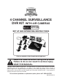
1
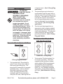
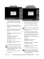
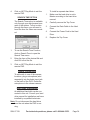
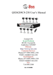
4 channel surveillance
dvr kit with 4-ir cameras
67139
Set up and Operating Instructions
Visit our website at: http://www.harborfreight.com
Read this material before using this product.
Failure to do so can result in serious injury.
Save this manual.
Copyright© 2009 by Harbor Freight Tools®. All rights reserved. No portion of this manual or any artwork
contained herein may be reproduced in any shape or form without the express written consent of
Harbor Freight Tools. Diagrams within this manual may not be drawn proportionally. Due to continuing
improvements, actual product may differ slightly from the product described herein. Tools required for
assembly and service may not be included.
For technical questions or replacement parts, please call 1-800-444-3353.
Manual Revised 10h
Contents
Important SAFETY
Information���������������������������� 3
NETWORK SETUP���������������������� 15
What you will need to set
up The DVR Online������������������� 15
General Safety Warnings������� 3
Connecting Your DVR to
the Router�������������������������������� 15
DVR-Camera Kit Safety
Warnings�������������������������������������� 4
Finding your DVR’s Internal
IP Address ��������������������������������� 15
Grounding��������������������������������� 5
Preparing Your Computer
for Viewing the DVR�������������� 16
Grounded Tools: Tools
with Three Prong Plugs������� 5
Double Insulated Tools:
Tools with Two Prong
Plugs���������������������������������������������5
Installing Software��������������� 16
Adding DVR to Trusted Sites16
Viewing Your DVR Outside
of Your Network������������������� 17
Extension Cords������������������������� 6 Programming the DVR��������� 18
Symbology�������������������������������������6
CHANNEL (CAMERA) SETUP�������� 18
Specifications�������������������������� 7
RECORD SETUP������������������������������ 19
Trademark
Acknowledgements���������������� 7
RECORD FRAME RATE������������������ 19
Unpacking��������������������������������������� 7
RECORD SCHEDULE���������������������� 20
Instructions for putting
into use������������������������������������ 8
SENSOR SETUP������������������������������ 20
Components���������������������������������� 8
MISCELLANEOUS SETUP�������������� 23
Operating Instructions���� 10
VIDEO QUALITY������������������������������ 20
HARD DRIVE SETUP����������������������� 22
Network Set up Sub-Menu����� 27
Work Area Set Up���������������������� 10
Backup Program������������������ 31
Setup Overview�������������������������� 10
Audio Connection��������������������� 34
Hard Disk Installation����������� 34
Setting up the DVR with a
TV MONITOR ���������������������������� 11 Maintenance/Servicing������ 35
DVR/CAMERA CONNECTIONS������ 11
Cleaning and Maintenance��� 35
DVR/TV MONITOR CONNECTION�� 11
NTSC/PAL Output Select��������� 35
Starting the DVR������������������� 12
Troubleshooting���������������������� 36
OPERATING INSTRUCTIONS���� 13
RECORDING������������������������������������ 13
PLAYBACK��������������������������������������14
REV 10h
SKU 67139
For technical questions, please call 1-800-444-3353.
Page 2
NOTICE is used to
address practices
not related to personal injury.
Save This Manual
Keep this manual for the safety warnings and precautions, assembly, operating, inspection, maintenance and cleaning
procedures. Write the product’s serial
number in the back of the manual near the
assembly diagram (or month and year of
purchase if product has no number). Keep
this manual and the receipt in a safe and
dry place for future reference.
CAUTION, without
the safety alert
symbol, is used to address
practices not related to
personal injury.
General Safety Warnings
WARNING Read all safety
warnings and instructions.
Failure to follow the warnings and
instructions may result in electric
shock, fire and/or serious injury.
Save all warnings and
instructions for future reference.
Important SAFETY
Information
In this manual, on the labeling,
and all other information provided with this product:
This is the safety alert
symbol. It is used to alert
you to potential personal
injury hazards. Obey all
safety messages that
follow this symbol to avoid
possible injury or death.
DANGER indicates
a hazardous
situation which, if not
avoided, will result in death or
serious injury.
WARNING
indicates a
hazardous situation which, if
not avoided, could result in
death or serious injury.
CAUTION, used
with the safety
alert symbol, indicates a
hazardous situation which, if
not avoided, could result in
minor or moderate injury.
SKU 67139
1.
Work area safety
a.Keep work area clean and well lit.
Cluttered or dark areas invite accidents.
b.Keep children and bystanders
away while operating the unit.
Distractions can cause you to lose
control.
2.
Electrical safety
a.Power plugs must match the
outlet. Never modify the plug in
any way. Do not use any adapter
plugs with grounded plugs. Unmodified plugs and matching outlets
will reduce risk of electric shock.
b.Do not expose DVR Unit to rain or
wet conditions.
c. Do not abuse the cord. Never use
the cord for carrying, pulling or
unplugging the unit. Keep cord
away from heat, oil, sharp edges
or moving parts. Damaged or
For technical questions, please call 1-800-444-3353.
Page 3
mented – it prevents sustained electrical shock.
entangled cords increase the risk of
electric shock.
3.
Personal safety
4.
WARNING: Handling the cord on
this product will expose you to lead,
a chemical known to the State of
California to cause cancer, and birth
defects or other reproductive harm.
Wash hands after handling. (California Health & Safety Code § 25249.5,
et seq.)
5.
The warnings, precautions, and instructions discussed in this instruction
manual cannot cover all possible conditions and situations that may occur.
It must be understood by the operator
that common sense and caution are
factors which cannot be built into this
product, but must be supplied by the
operator.
Stay alert, watch what you are
doing and use common sense
when operating the unit. Do not
use while you are tired or under
the influence of drugs, alcohol or
medication.
4.
Service
Have your DVR serviced by a
qualified repair person using only
identical replacement parts. This
will ensure that the safety of the unit
is maintained.
DVR-Camera Kit Safety Warnings
1.
Maintain labels and nameplates on
the unit. These carry important safety
information. If unreadable or missing, contact Harbor Freight Tools for a
replacement.
2.
This product is not a toy. Keep it out
of reach of children.
3.
People with pacemakers should
consult their physician(s) before use.
Electromagnetic fields in close proximity to heart pacemaker could cause
pacemaker interference or pacemaker failure. In addition, people with
pacemakers should:
• Avoid operating alone.
• Do not use with power switch locked
on.
• Properly maintain and inspect to
avoid electrical shock.
• Any power cord must be properly
grounded. Ground Fault Circuit Interrupter (GFCI) should also be imple-
SKU 67139
Save these
instructions.
For technical questions, please call 1-800-444-3353.
Page 4
of electric shock. (See 3-Prong Plug
and Outlet.)
Grounding
To prevent
electric shock
and death from
incorrect grounding
wire connection:
Check with a qualified
electrician if you are in doubt
as to whether the outlet is
properly grounded. Do not
modify the power cord plug
provided with the tool. Never
remove the grounding prong
from the plug. Do not use the
tool if the power cord or plug
is damaged. If damaged, have
it repaired by a service facility
before use. If the plug will not
fit the outlet, have a proper
outlet installed by a qualified
electrician.
2.
The grounding prong in the plug is
connected through the green wire inside the cord to the grounding system
in the tool. The green wire in the cord
must be the only wire connected to
the tool’s grounding system and must
never be attached to an electrically
“live” terminal. (See 3-Prong Plug
and Outlet.)
3.
The tool must be plugged into an
appropriate outlet, properly installed
and grounded in accordance with all
codes and ordinances. The plug and
outlet should look like those in the
preceding illustration. (See 3-Prong
Plug and Outlet.)
Double Insulated Tools: Tools
with Two Prong Plugs
Grounded Tools: Tools with Three
Prong Plugs
Outlets for 2-Prong Plug
3-Prong Plug and Outlet
1.
Tools marked with “Grounding Required” have a three wire cord and
three prong grounding plug. The
plug must be connected to a properly
grounded outlet. If the tool should
electrically malfunction or break
down, grounding provides a low
resistance path to carry electricity
away from the user, reducing the risk
SKU 67139
1.
Tools marked “Double Insulated” do
not require grounding. They have
a special double insulation system
which satisfies OSHA requirements
and complies with the applicable
standards of Underwriters Laboratories, Inc., the Canadian Standard
Association, and the National Electrical Code. (See Outlets for 2-Prong
Plug.)
For technical questions, please call 1-800-444-3353.
Page 5
3.
4.
5.
6.
7.
As the distance from the supply outlet
increases, you must use a heavier
gauge extension cord. Using extension cords with inadequately sized
wire causes a serious drop in voltage,
resulting in loss of power and possible tool damage.
(See Table A.)
The smaller the gauge number of the
wire, the greater the capacity of the
cord. For example, a 14 gauge cord
can carry a higher current than a 16
gauge cord. (See Table A.)
RECOMMENDED MINIMUM WIRE
GAUGE FOR EXTENSION CORDS*
(120/240 VOLT)
NAMEPLATE
AMPERES
(at full load)
0 – 2.0
18
18
18
18
16
2.1 – 3.4
18
18
18
16
14
3.5 – 5.0
18
18
16
14
12
5.1 – 7.0
18
16
14
12
12
7.1 – 12.0
18
14
12
10
-
12.1 – 16.0
14
12
10
-
-
16.1 – 20.0
12
10
-
-
-
TABLE A
* Based on limiting the line
voltage drop to five volts at
150% of the rated amperes.
Symbology
When using more than one extension cord to make up the total length,
make sure each cord contains at
least the minimum wire size required.
(See Table A.)
If you are using one extension cord
for more than one tool, add the
nameplate amperes and use the sum
to determine the required minimum
cord size. (See Table A.)
If you are using an extension cord
outdoors, make sure it is marked with
the suffix “W-A” (“W” in Canada) to
indicate it is acceptable for outdoor
use.
EXTENSION CORD
LENGTH
150’
2.
Grounded tools require a three wire
extension cord. Double Insulated
tools can use either a two or three
wire extension cord.
Protect the extension cords from
sharp objects, excessive heat, and
damp or wet areas.
100’
1.
8.
75’
Extension Cords
dition. Always replace a damaged
extension cord or have it repaired by
a qualified electrician before using it.
50’
Double insulated tools may be used
in either of the 120 volt outlets shown
in the preceding illustration. (See
Outlets for 2-Prong Plug.)
25’
2.
Double Insulated
Canadian Standards Association
Underwriters Laboratories, Inc.
V~
A
Volts Alternating Current
Amperes
No Load Revolutions per Minute
n0 xxxx/min. (RPM)
Make sure the extension cord is properly wired and in good electrical con-
SKU 67139
For technical questions, please call 1-800-444-3353.
Page 6
Specifications
Video Standard NTSC/PAL
Hard drive
4-Input Channels/1-Output
Channel
1-Input Channel/1-Output
Channel
NTSC:
20x480@30fps
(each CH)
Resolution
PAL:
720x576@25fps
(each CH)
Full-DI, 1-Channel/4Features
Channel/1-Channel
Playback
NTSC: 720x240@
60fps (Total)
Resolution PAL:
720x288@50fps
(Total)
Variable Frame
Features
Rate, up to 200 hrs,
recording time
Quality
4 Levels
250 gigabite hard drive
Audio
ADPCM2 CODEC
Video
MPEG4 Compression
Motion
Detection
Selectable Area and Sensitivity
Detection
Video
Audio
Preview
Recording
Microprocessor 32-bit RISC Processor
Network
Interface
RJ45
HDD Port
Support SATA Hard drive
USB Port
USB 2.0
Audio Port
Optional
Remote
Control
Support IR Remote Control
Adapter
Input: 120 V ~ / 60 Hz
Output: 12 VDC, 5A
Included
Accessories
4 Infrared Day/Night Cameras
(Two 3.6mm wide angle and
two 6mm for longer range, all
are color in daylight and black
& white infrared night viewing),
Camera Cables, Remote
Control, USB Cable, Cable
Splitter, Power Cord, Power
Adapter, Software CD, Two AAA
Batteries,
NOTICE: Camera surveillance may be
prohibited by laws that vary from
state to state. Check laws in your
area before using for surveillance.
This device complies with part 15 of
the FCC Rules. Operation is subject to the
following two conditions: (1) This device
may not cause harmful interference, and
(2) this device must accept any interference received, including interference that
may cause undesired operation.
To the extent that you use this unit
with software other than what is provided,
we will not be responsible for any loss or
damage to your computer or contents.
Trademark Acknowledgements
Ethernet, Internet Explorer (IE), ActiveX, DivX, and Windows XP, Windows
Vista are registered trademarks of the
respective holders.
Unpacking
When unpacking, make sure that the
item is intact and undamaged. If any parts
are missing or broken, please call Harbor
Freight Tools at 1-800-444-3353 as soon
as possible.
REV 10h
SKU 67139
For technical questions, please call 1-800-444-3353.
Page 7
Instructions for
putting into use
8
9
10
11
12
13
Read the entire Important
Safety Information
section at the beginning of this
manual including all text under
4
5
6
7
3
subheadings therein before set
up or use of this product.
Figure 2 - Front Panel
To prevent
serious injury
from accidental
operation:
Unplug the unit from its
electrical outlet before
assembling or making any
adjustments to the wiring.
Components
USB Cable
Software CD
Batteries
Power Adapter
Power Cord
Camera
Cables
Cable Splitter
DVR
Cameras
Remote Control
Figure 1
USB Port
2
1
15
14
17
16
1.
PWR - LED indicates unit is on.
2.
HDD - LED indicates hard drive is in
use.
3.
CH1
- Channel 1
4.
CH2
- Channel 2
5.
CH3
- Channel 3
6.
CH4
- Channel 4
7.
Quad
- View all channels
8.
REW
- Rewind in playback mode.
9.
PAUSE - Pause in Playback Mode,
Auto Sequence Display in Live Mode.
10. PLAY
- Play.
11. FWD
Mode.
- Fast Forward in Playback
12. STOP
- Stop.
13. REC
- Record.
14. [MENU]
15. [UP]
- Move Left / Menu / ESC.
- Move up.
16. [SEL]
17. [DOWN]
- Move Right / Select / Edit.
- Move down.
REV 10h
SKU 67139
For technical questions, please call 1-800-444-3353.
Page 8
1
2
0-9
All
Menu
3
4
5
6
7
8
2.
4.
VIDEO OUTPUT - monitor connection.
5.
CH1 - Camera 1 connection.
6.
CH2 - Camera 2 connection.
7.
CH3 - Camera 3 connection.
8.
CH4 - Camera 4 connection.
9.
POWER INPUT JACK - 12V DC
Connector from main power adapter.
Select
Forward
Record
Pause /
Playback
AUDIO INPUT - Microphone connection.
LAN - Internet/LAN Ethernet port.
Left / Right
Play
AUDIO OUTPUT - Speaker connection.
3.
Up / Down
Rewind
Figure 3 - Back Panel
1.
/
/
SEL
9
Number Keys
(1 - 4 Channel
Select)
Display All
Channels
Enter / Exit
Menu
Stop
Figure 4
Audio/ Search or switch
Search audio channels
Turn on/off audio
Mute
output
REV 10h
SKU 67139
For technical questions, please call 1-800-444-3353.
Page 9
forwarding knowledge. Following are
the possible set up options.
Operating Instructions
Read the entire Important
Safety Information
section at the beginning of this
manual including all text under
subheadings therein before set
up or use of this product.
Work Area Set Up
1.
Designate a work area that is clean
and well-lit. The work area must not
allow access by children or pets to
prevent distraction and injury.
2.
Route the power cord and all cabling
along a safe route without creating a
tripping hazard or exposing the cord
and cables to possible damage.
3.
Use a surge protector (sold separately) to help guard against electrical
power fluctuations.
4.
IMPORTANT: Before mounting any
of the cameras, test the unit by hooking up all the connections, and testing all the features to insure the unit
is working properly. There are two
6mm cameras for longer range, and
two 3.6mm cameras for wider angle,
shorter range, viewing. Test the
cameras for the best location before
installing. Each camera is labeled on
the side of the unit.
Setup Overview
This unit can be set up in several different configurations. The simplest is
with a TV monitor. For set up through
the internet there are specific software requirements and you will need
to have an understanding of your modem, your computer and your internet
connection settings, as well as port
SKU 67139
1.
DVR with a TV monitor (sold separately) - This is the simplest set up
that allows you to adjust all the settings, view and record live images
and play back any recordings. You do
not have computer or internet capabilities with this set up.
2.
DVR with a computer and a TV monitor (both sold separately) - This set
up allows you to view recorded files
on a computer connected to the unit.
You cannot record when the unit is
connected directly to the computer.
3.
DVR and a computer, connected
to the same modem and accessed
through your web browser (computer
and modem sold separately) - This
set up allows you to adjust all the
settings, view and record live images,
and play back any recordings through
your web browser. You will first need
a TV monitor to set up the system.
This option may not function with all
web browsers.
4.
Remote access through your internet
service - This arrangement allows
remote access to the DVR through
the internet. You will need to have the
unit already set up as in the previous paragraph, and have computer
and internet set up knowledge of port
forwarding and your modem’s external IP address in order to set up this
configuration.
For technical questions, please call 1-800-444-3353.
REV 10h
Page 10
(the largest connector on the cable)
to one of the camera connections
on the back of the DVR (CH1, CH2,
CH3, or CH4). To attach the BNC
Connector:
Setting up the DVR with
a TV MONITOR
DVR/CAMERA CONNECTIONS
a.Align the slots on the BNC Connector with the pins on the DVR connection and push the BNC Connector in
so the pins slide into the slots.
Figure 5 below shows the cable connections for the DVR and cameras.
Camera
Power Cord
DVR
b.Turn the connector clockwise to lock
the pins in place.
6
1
5.
Attach the black power connector at
the BNC end of the same cable to
one of the remaining Cable Splitter
connectors.
6.
Attach the connectors at the other
end of the Camera Cable to the same
color connectors of one of the Cameras.
7.
Repeat steps 4 through 6 for each of
the other three Cameras and Camera
Cables.
3
4
2
5
Camera
Cable
Cable Splitter
Power Adapter
BNC
Connector
DVR/TV MONITOR CONNECTION
Figure 5
4a
4b
To connect the camera and power
components to the DVR:
1.
Attach the Power Cord to the Power
Adapter.
2.
Attach the Power Adapter Cable to
the single end of the Cable Splitter.
3.
Attach the connector marked “DVR
Power” to the Power Input Jack on
the back of the DVR.
4.
Working with one Camera Cable, attach the yellow video BNC Connector
You will initially need to connect
the DVR to a TV monitor in order to
adjust the settings regardless of your
final intended set up. To hook up to a
TV, such as the Monitor (SKU 66556,
sold separately), plug the BNC connector of the video cable into the
Video Output slot, and the other end
into the video Input or channel slot
on the TV monitor. Plug the TV into a
wall outlet. The unit will power up.
Note: For model 66556, if needed, change
the channel on the front of the
monitor so the light on the monitor is
green and adjust the image using the
adjustment knobs on the back of the
monitor.
REV 10h
SKU 67139
For technical questions, please call 1-800-444-3353.
Page 11
Starting the DVR
1.
Once the unit is connected and
plugged in, the Power LED will light
up.
checking hdd……
master [ maxtOr s tm3250310a]-new-dvr
FOrmat hdd cOnFirm
(select) FOrmat / (menu) cancel?
Note: When detecting a new hard drive,
the DVR will prompt you to format the
hard drive.
2.
Initially, the DVR will boot-up and display the current version and release
date of the DVR firmware for a few
seconds.
checking hdd……
master
Press (SEL) to format the new hard
drive, or (MENU) to cancel and enter
the system.
4.
After the DVR has finished booting
up, it will enter the mode it is programmed for, including recording if
it is the scheduled time period for
recording.
[maxtOr stm3250310a]
slave……
3.
The DVR will then automatically detect the hard drive and show the hard
drive information.
If there is any problem with the hard
drive, the DVR will display the information and will not finish its boot up
program.
REV 10h
SKU 67139
For technical questions, please call 1-800-444-3353.
Page 12
OPERATING INSTRUCTIONS
RECORDING
1
2
3
4
A-REC [M] 39%
2009/02/22 16:09:44
1.
Set up all the functions of the DVR
following “Programming the DVR”.
2.
Press the record button to begin
recording according to the schedule
you have set.
Each Channel set to record will display a recording symbol [ ] next to
the channel number.
S-REC - Motion sensor recording.
N-REC - No recording.
OTHER DATA
The following will display along the
remaining lower edge of the screen:
[M] or [S]- Indicates which hard drive
is in use (M=Master, S= slave).
#% - Displays the percentage of hard
drive disk space used.
YYYY/MM/DD - Displays current
Year/Month/Day.
HH:MM:SS - Displays current time
(hours:minutes:seconds).
Note: If the date, time or any other
settings are incorrect you will need to
stop recording and go back to the set
up menu to reset the functions.
STOPPING
AUDIO
The channel which is set to audio
will display one of the following audio
symbols next to the record symbol.
- Audio output is off.
To stop recording, press the
STOP button. If the password function is enabled you will be prompted
for the password and will not be able
to stop recording without the current
password.
- Audio output is on and audio
is attached to the indicated channel.
When the symbol is red it indicates
that audio is currently recording.
To mute the audio signal, press the
DOWN button. The audio signal
will continue to record and can be
heard in playback mode.
RECORDING MODE
One of the following will display along
the bottom left of the screen:
A-REC - Normal recording.
SKU 67139
For technical questions, please call 1-800-444-3353.
REV 10h
Page 13
PLAYBACK
Estimated Record Time
The following charts show the
estimated recording time based on
160GB of hard drive space:
Type Quality
60 48 32 16 1
fps fps fps fps fps
Highest 62 78
High
88 110
NTSC
Normal 107 134
Low
120 150
Type Quality
PAL
To watch recorded videos, you will
need to enter Playback mode. To enter Playback mode, first press STOP
to stop recording.
116
165
201
225
232
330
401
450
search videO
3720
5280
6420
7200
DISK: MASTER
SLAVE [NONE]
08/09/19 1 1:16:31 - 0 8/09/19
15:05:48
TYPE: EVENT
TIME
PLAY: E VENT LIST
00006 T 2008/09/19
00006 T 2008/09/19
00006 T 2008/09/19
00006 T 2008/09/19
00006 T 2008/09/19
00006 T 2008/09/19
00006 T 2008/09/19
50 36 24 12 1
fps fps fps fps fps
Highest 64 89
High
90 125
Normal 110 153
Low
123 171
133
188
229
256
267
375
458
513
3200
4500
5500
6150
To read the above charts, refer
to the total frame rate and video
quality settings which you have set
the cameras to (under “Setting up
the DVR Functions Through the
Main Menu” Section - sub sections:
“Record Frame Rate” and “Video
Quality”).
NTSC and PAL are different
broadcast standards. Each country
uses one standard. Your unit is set to
NTSC for use in the United States.
The fps (frames per second) is the
total frame rate. The Quality is the
video quality. The numbers in the
body of the the charts are the number
of hours of record time. For instance,
in the top chart (Type=NTSC), if you
set the unit to a total of 60 fps and
the quality to High, you will be able
to record for 88 hours to a hard drive
which has 160GB of available space.
A larger hard drive will allow for more
recording time.
) MOVE
(
(
15:07:40
14:07:40
13:07:40
12:07:40
11:07:40
10:07:40
09:07:40
(SEL)SELECT
) PLAY (MENU) PREV MENU
Press the PLAY button to go to
PLAYBACK mode and display the
“Search Video” screen. The most
recent recording will play.
To play a different recording:
1.
Press the [MENU] button while in
PLAYBACK mode. The system will
list all the recordings, with the most
recent at the top of the list.
2.
Press the UP or DOWN
to select a recording.
3.
Press PLAY
4.
Press Stop to stop playing the recording.
button
to play the recording.
REV 10h
SKU 67139
For technical questions, please call 1-800-444-3353.
Page 14
2.
The 67139 allows you to view your
DVR through the Internet. This is
especially useful for remote security
monitoring.
Connect the network cable (sold
separately) to the back of the DVR in
the Ethernet port.
3.
Set up the unit using a TV monitor so
you can view the Main Menu during
set up. You will not need the TV monitor once the set up is complete.
Connect the other end of the network
cable to an available port on the
router. The port should be labeled 1-4
or 1-8.
4.
Power on the DVR by reconnecting
the power cable on the back of the
DVR.
5.
A green light should light up on the
back of the DVR at the Ethernet connection and also at the port on the
router.
NETWORK SETUP
What you will need to set up The
DVR Online
You will need:
• The DVR connected to a router.
• The router connected to the Internet.
Finding your DVR’s Internal IP
Address
• A PC or laptop that is connected to
the same router as the DVR.
• A compatible web browser (instructions were developed with a common web browser , other browsers may not be compatible).
• A genuine and fully updated version
of Windows XP or Vista.
Note: The computer and DVR need to be
connected to the same router. The
computer is required at the location
to view the DVR for initial set up, but
is not needed for remote access once
the unit is set up and working properly.
Connecting Your DVR to the
Router
1.
Power off the DVR by removing the
power cable from the back of the
DVR.
By default, the DVR IP mode is set to
Static. Changing the Static to DHCP,
will cause the DVR to automatically
retrieve an IP address from the connected router. Unless your network
requires a static IP address, leave the
DVR IP Allocation set as DHCP.
To retrieve the address information:
a.Press Menu.
b.Move the cursor next to Network
Setup and press Select.
REV 10h
SKU 67139
For technical questions, please call 1-800-444-3353.
Page 15
c. Check that the “IP Allocation” is set
to DHCP.
1.
Insert Software CD into your computer’s CD-ROM drive.
d.Write down your IP address, subnet Mask, Gateway and HTTP Port
(default is 80). This information will
be used in the next few steps to view
the DVR on your computer and the
Internet.
2.
Open the CD directory.
3.
Double click on “DxClient 2.7.1ENG”.
4.
Run the “Install” program.
Follow the setup wizard to finish the
installation.
e.Go to the User Setup menu and
write down the admin ID and admin
password. The default is “admin”
and “111111”.
Adding DVR to Trusted Sites
Every computer that is accessing
the DVR will need to be configured
to download and run ActiveX controls. This is a one time change and
only needs to be made on the computer that is accessing the DVR. This
can be done by changing your web
browser settings so it only affects
websites that you specifically add
to the trusted sites list. Or you can
change the setting for all websites.
It is recommended that you only
change the setting for your trusted
sites.
Note: If your router does not support
DHCP, contact your network administrator to supply you with your IP
information. If the DVR needs to store
PPPoE (DSL/ADSL) settings, contact
your ISP (Internet Service Provider)
for the proper settings.
Preparing Your Computer for
Viewing the DVR
Installing Software
CAUTION: Lowering the safety settings of
your computer can open your computer up to viruses. Do this at your
own risk.
To add the DVR’s IP address to the
Trusted Sites on a common web
browser:
1.
Open your web browser.
The Software CD includes a PC viewer program for the DVR (DxClient
2.7.1). This program is for backing up
video files and remote access. You
may also need to change the security
settings of the web browser.
2.
Click on TOOLS.
3.
Click on INTERNET OPTIONS.
4.
Click on SECURITY Tab.
5.
Click on TRUSTED SITES.
To install the PC Viewer program:
6.
Click on SITES button.
SKU 67139
For technical questions, please call 1-800-444-3353.
REV 10h
Page 16
7.
Type in the IP address of the DVR in
the following format:
HTTP://129.168.1.108
Note: The bold underlined numbers are
your IP address and will be different
from the numbers shown in the above
example.
8.
If “Require server verification (https:)
for all sites” is selected you will need
to uncheck the selection box.
9.
Click ADD.
10. Close window.
To change the default setting for the
TRUSTED SITES zone to low, on the
Main Settings:
1.
Click on DEFAULT LEVEL.
2.
Change security level of the zone to
“Low” by sliding the slider to the bottom.
3.
This will allow ActiveX controls from
the DVR to be downloaded and the
DVR to be viewed on the computer.
4.
Click APPLY.
5.
Click OK.
You should now see the connected
cameras on the computer screen in
the DxClient backup program. Follow
the instructions for “Backup Program”
to use the software.
Viewing Your DVR
Outside of Your Network
Once you have successfully set up
and viewed your DVR through a
router, you are now able to set up
your router to view the DVR while at
a remote location. This process is
called Port Forwarding. Port Forwarding is required if you want to view
the DVR from a computer that is not
connected to the same router. This
process opens a path on your home/
business network to allow you to view
your DVR video feed from outside
your network (over the Internet).
There are many makes and models
of routers. You will need to follow the
instructions from your router’s manufacturer for port forwarding. Consult
online sources or have a qualified
computer technician complete this
task if needed.
Once you have successfully set up
port forwarding from the modem
where the DVR is located, you will be
prompted to enter your user name
(default: admin), password (default:111111) and install ActiveX controls. You will now be able to view the
DVR from any PC in the world with
internet access and proper computer
settings.
REV 10h
SKU 67139
For technical questions, please call 1-800-444-3353.
Page 17
Programming
the DVR
CHANNEL (CAMERA) SETUP
1
o n
Main Menu Directory:
Camera Setup
Record Setup
Record Frame Rate
Video Quality
Main Record Schedule
Menu Sensor Setup
Hard Drive Setup
Miscellaneous Setup
Network Setup
Language
Reset Menu
channel setup
3 on
Change Password
Set Time
Hidden Channel
Audio Port Setup
Image Parameters
Password Enable
Keypad Tones
Seq. Dwell Time
To set the functions of the DVR you
will need to select and adjust items
from the Main Menu.
(
(
HIGH
E NGLISH
)MOVE (SEL)SELECT ( MENU)EXIT
1.
Press [Menu] to enter the Main Menu.
2.
To access the menu options and
make selections within the Main
Menu and Sub-Menus:
4 on
)Move ( SEL) Select ( MENU) Esc
The Channel (Camera) Setup submenu allows you to turn the cameras
on or off.
1.
In the Channel Set Up Menu, press
the arrow keys [ , ,
and
] to
select a channel (camera).
2.
Press [SEL] to change the setting
between “on” or “off”.
3.
Press [MENU] to exit the Camera
Setup sub-menu once all the camera
channels have been set.
main menu
CAMERA SETUP
RECORD SETUP
RECORD FRAMERATE
VIDEO qUALITY
RECORD SCHEDULE
SENSOR SETUP
HARD DRIVE SETUP
MISCELLANEOUS SETUP
NETWORK SETUP
LANGUAGE
RESET MENU
2 on
Note: If a channel is set to OFF in Channel Setup, the DVR will not record
from that camera, and the Frame
Rate will not be able to be set for that
camera.
a.Press up and down to select items.
b.Press [SEL] to change an option.
c. Press [MENU] to save any changes
and return to the previous Menu.
REV 10h
SKU 67139
For technical questions, please call 1-800-444-3353.
Page 18
RECORD SETUP
1 ON
2
RECORD FRAME RATE
1 3 FPS
NO
2
5 FPS
record Framerate
record setup
TOTAL 36 FPS
3 ON
(
3 2 5FPS
4 ON
)MOVE ( SEL) SELECT (MENU) ESC
(
4
)MOVE
(SEL)+ (
3FPS
)-
(MENU) EXIT
The total number of photos taken
per second is divided among the
cameras. The total frame rate of all
the cameras in use is set to 60fps
(frames per second). The higher settings produce better images, but use
up more hard drive space.
The Record Setup sub-menu allows
you to choose which channels (cameras) will record.
1.
In the Record Setup sub-menu, press
and
] to
the arrow keys [ , ,
select a channel (camera).
2.
Press [SEL] to change the setting
between “on” or “off”.
1.
3.
Press [MENU] to exit the Record
Setup sub-menu once all the camera
channels have been set.
In the Record Frame Rate sub-menu,
and
press the arrow keys [ , ,
] to select a channel (camera).
2.
Press [SEL] to increase, or STOP
to decrease, the number of frames
per second for that camera.
3.
Repeat step 1 and 2 for each camera, keeping the total number of
frames per second (displayed in the
center of the screen) at or below 60.
4.
Press [MENU] to exit the Record
Frame Rate sub-menu once all the
camera frame rates have been set.
Note: If a channel has been disabled (set
to “off”) in the Channel Setup, it will
not be able to record, and “NOCAM”
will display for that channel on the
screen in the Record Setup submenu.
Note: The DVR will automatically adjust
the largest frame rate to a smaller
value if you enter more than a total of
60fps for all the cameras.
Note: If you have your DVR set to PAL,
your maximum framerate is 50fps.
SKU 67139
For technical questions, please call 1-800-444-3353.
Page 19
The time line shows a 24 hour period,
based on AM/PM (0=12).
VIDEO QUALITY
main menu
CAMERA SETUP
RECORD SETUP
RECORD FRAMERATE
VIDEO qUALITY
RECORD SCHEDULE
SENSOR SETUP
HARD DRIVE SETUP
MISCELLANEOUS SETUP
NETWORK SETUP
LANGUAGE
RESET MENU
(
1.
In the Record Schedule sub-menu,
press the arrow keys [ , ,
and
] to move the marker to the desired time.
2.
Press [SEL] to modify the recording
mode. The Mode options are:
HIGH
ENGLISH
a.NO-RECORD (white) - The DVR will
not record during this period.
)MOVE ( SEL)SELECT (MENU)ESC
Video Quality can be set to Highest,
High, Normal, and Low. The higher
settings produce better images, but
use up more hard drive space. The
cameras are all set to the same setting in one step in the Main Menu.
In the Main Menu, use the arrow keys
to select Video Quality. Press the
[SEL] button to change between the
four video quality settings.
RECORD SCHEDULE
b.NORMAL RECORD (red) - The DVR
will record continuously during this
period.
c. SENSOR RECORD (S) - The DVR
will begin recording when the motion
sensor is activated.
3.
Press [MENU] to exit the Record
Schedule sub-menu once the recording options have been set.
Note: Once all the menu options are set,
press the REC button to activate
the Record Schedule.
SENSOR SETUP
record schedule
am
sensOr setup
pm
0… 3… 6… 9… 0… 3…. 6… 9…
SENSORED RECORD TIME
ALARM ON TIME
NO-RECORD
NORMAL-RECORD
S SENSOR -RECORD
30
05
MOTION DETECTOR SETUP
(
)MOVE (SEL)SELECT ( MENU) EXIT
(
The Record Schedule sub-menu allows you to customize the recording
time for the cameras. The cameras
are all set to the same schedule.
SKU 67139
)MOVE ( SEL)SELECT (MENU)ESC
The Sensor Setup sub-menu sets
how long (in seconds) the cameras
will record once the sensor is activated, and whether or not, and how long
(in seconds), the alarm will sound.
For technical questions, please call 1-800-444-3353.
Page 20
This menu also has the sub-menu:
“Motion Detector Setup”, for setting
motion detection options.
MOTION DETECTOR SETUP
motion detector setup
SENSOR RECORD TIME
1.
In the Sensor Setup sub-menu, press
the up or down arrow keys [ , ] to
select “Sensor Record Time”.
2.
Press [SEL] to increase, or STOP
to decrease, the number of seconds
to record once the sensor is activated. The recording time can be set to
5, 10, 15, 20, 25 or 30 seconds.
CH1
CH2
CH3
CH4
(
ON
ON
ON
ON
Level
Level
Level
Level
2
2
2
2
Area
Area
Area
Area
)MOVE ( SEL)SELECT (MENU)ESC
This sub-menu allows you to set the
motion detection options for each
camera.
ALARM ON TIME
1.
In the Sensor Setup sub-menu, press
the up or down arrow keys [ , ] to
select “Alarm on Time”.
1.
In the Sensor Setup sub-menu, press
the up or down arrow keys [ , ] to
select “Motion Detector Setup”.
2.
Press [SEL] to switch between the
following options:
2.
Press [SEL] to enter the Motion Detector Setup sub-menu.
3.
and
Press the arrow keys [ , ,
] to move between the channels
and the options for each. Press [SEL]
button to change the settings for each
option. The options and settings are:
a.CONT - The alarm will sound once
the motion sensor is activated and
will continue until any key is pressed
on the DVR or remote.
b.OFF - No alarm will sound.
c. # - The alarm will sound for the number of seconds indicated. The alarm
can be set to 5, 10, 15, 20, 25 or 30
seconds. Press [SEL] to increase, or
[STOP] to decrease the number.
a.On/Off - Use the [SEL] button to
toggle between enabling (On) or disabling (Off) motion detection recording for each channel.
b.Level - Use the [SEL] button to set
the sensitivity level from 1 (lowest) to
3 (highest).
c. Area - Use the [SEL] button to enter
this sub-menu.
SKU 67139
For technical questions, please call 1-800-444-3353.
Page 21
It also shows hard drive size and how
much memory is used.
AREA SELECTION
1.
In the Main Menu, press the up or
down arrow keys [ , ] to select
“Hard Drive Setup”.
2.
Press [SEL] to enter the Hard Drive
Setup sub-menu.
OVERWRITE ENABLE/DISABLE
This sub-menu shows the camera’s
view broken up into a grid. You
choose which sections of the image
detect motion.
1.
hard drive setup
OVERWRITE ENABLED
[ ON]
MAXTOR STM250310AS
MASTER HDD SIZE
250203MB
MASTER HDD USED
124931MB
MASTER HDD FORMAT
To set individual blocks of the screen:
SLAVE HDD SIZE
SLAVE HDD USED
SLAVE HDD FORMAT
a.Press the arrow keys [ , ,
and
] to select a block in the grid
b.Press the [SEL] button to toggle between showing the image in the block
(motion is detected where the image
can be seen), or shading the image in
the block (motion will not be detected
in theses areas).
(
50%
N/A
N /A
) MOVE ( SEL)SELECT (MENU)EXIT
1.
In the Hard Drive Setup sub-menu,
press the arrow keys [ , ] to select
“Overwrite Enabled”.
2.
Press [SEL] to switch between the
“ON” which will overwrite the oldest
video when the hard drive is full, and
“OFF” which will stop recording when
the hard drive is full.
2.
To disable all areas of the screen
from detection, press STOP . The
screen will be completely shaded.
3.
To have all of the camera’s viewing
area detect motion, select QUAD. All
of the screen will be in view.
MASTER HDD FORMAT
4.
Press [MENU] to exit sub-menu.
1.
5.
Press [MENU] twice more to go back
to the Main Menu.
In the Hard Drive Setup sub-menu,
press the arrow keys [ , ] to select
“Master HDD Format”.
2.
Press [SEL] to Format the hard drive.
This will erase all recorded video
from the hard drive and will make the
hard drive readable by the DVR.
3.
You will be prompted for a password
before formatting. The default password is “111111”.
HARD DRIVE SETUP
The Hard Drive Setup sub-menu allows you to set whether to overwrite
old video once the hard drive is full,
and it allows you to format the hard
drive.
SKU 67139
For technical questions, please call 1-800-444-3353.
Page 22
CAUTION: All recorded video will be deleted when the hard drive is formatted.
4.
Press [MENU] to exit sub-menu.
CURRENT PASSWORD
[- - - - -]
PASSWORD
[- - - - -]
COMFIRM PASSWORD
[- - - - -]
NEW
MISCELLANEOUS SETUP
The miscellaneous setup sub-menu
allows access to a variety of functions
including changing the password,
setting the time, and setting the audio
port.
1.
In the Main Menu, press the up or
down arrow keys [ , ] to select
“Miscellaneous Setup”.
3.
2.
Press [SEL] to enter the Miscellaneous Setup sub-menu.
Note: The password must be 6 characters long, and can be any key except
[MENU].
CHANGE PASSWORD
4.
Enter the current password first, then
enter the new password. Re-enter the
new password to confirm.
Press [MENU] to exit sub-menu.
SET TIME
set time
2008/11/11
(
1.
2.
17:50:01
)MOVE ( SEL)SELECT (MENU) ESC
The default password is set to
“111111”. You may change the password, but be sure to write it down and
keep it in a safe place so you do not
forget the new password. To change
the password:
1.
In the Miscellaneous Setup submenu, press the arrow keys [ , ] to
select “Change Password”.
In the Miscellaneous Setup submenu, press the arrow keys [ , ] to
select “Set Time”.
2.
Press [SEL] to enter the sub-menu.
Press [SEL] to enter the sub-menu.
3.
Press [
] or [
] to select the
unit to change, then press [SEL] to
SKU 67139
The system date and time format is
YYYY/MM/DD and HH:MM:SS. To set
the date and time:
For technical questions, please call 1-800-444-3353.
Page 23
change the value. Repeat for each
value.
4.
AUDIO PORT SETUP
audio port setup
Press [MENU] to save and return to
the previous menu.
AUDIO PORT1-VIDEO CHANNEL
AUDIO PORT1-RECORD
HIDDEN CHANNEL
(
[ 1 ]
[ OFF ]
)MOVE ( SEL)SELECT (MENU)EXIT
To set up the Audio Port, first check
to see which camera you have set up
with a microphone (sold separately).
To enable the audio recording function:
The system provides the option to
hide a channel (camera) . The selected channel can still record while
it is hidden, the images are just not
viewable until playback. To hide a
channel:
1.
In the Miscellaneous Setup submenu, press the arrow keys [ , ] to
select “Audio Port Setup”.
2.
Press [SEL] to select the channel
number where the microphone is
located.
In the Miscellaneous Setup submenu, press the arrow keys [ , ] to
select “Hidden Channel”.
3.
Press the arrow keys [ ,
“Audio Port - Record”.
4.
2.
Press [SEL] to select the channel
number to hide.
Press [SEL] to toggle between setting
the audio “on” or “off”.
5.
3.
Press [MENU] to save and return to
the previous menu.
Press [MENU] to save and return to
the previous menu.
1.
SKU 67139
For technical questions, please call 1-800-444-3353.
] to select
Page 24
IMAGE PARAMETERS
PASSWORD ENABLE
In the Image Parameters sub-menu
you adjust the quality of the image.
To make the adjustments:
1.
In the Miscellaneous Setup submenu, press the arrow keys [ , ] to
select “Image Parameters”.
2.
Press [SEL] to enter the image so
you can edit the parameters.
You will always need the current
password to format the hard drive,
to reset the menu, or to access the
customer port. To access other parts
of the system, you can enable or disable the password. To turn password
access on or off:
1.
In the Miscellaneous Setup submenu, press the arrow keys [ , ] to
select “Password Enable”.
2.
Press [SEL] to toggle between “on”
and “off”.
KEYPAD TONES
3.
Press [ ] or [ ] buttons to select one
of the following settings, then press
[
] or [
] to adjust the levels.
CON: Contrast
BRI: Brightness
HUE: Hue
SAT: Saturation
4.
Press [MENU] to save and return to
the previous menu.
Some models have a buzzer sound
available for the [SEL] button. If
equipped, to set the buzzer sound for
the [SEL] button to on or off:
REV 10d
SKU 67139
For technical questions, please call 1-800-444-3353.
Page 25
1.
In the Miscellaneous Setup submenu, press the arrow keys [ , ] to
select “Keypad Tones”.
2.
Press [SEL] to toggle between “on”
and “off”.
SEQ. DWELL TIME
if one of the cameras is not properly
connected. To set this function on or
off:
1.
In the Miscellaneous Setup submenu, press the arrow keys [ , ] to
select “Video Sound Loss”.
2.
Press [SEL] to choose between “off”
and “on” to change the setting.
LANGUAGE
The Sequence Dwell function sets
the amount of time (1, 5, 10, 15, 30 or
60 seconds) that the system spends
on one setting. To set this function on
or off, and to set the time level:
1.
In the Miscellaneous Setup submenu, press the arrow keys [ , ] to
select “Seq. Dwell Time”.
2.
Press [SEL] to choose between “off”
and one of the time settings.
VIDEO LOSS SOUND
The default language is English. To
change the OSD language to a different
language:
1.
In the Main Menu, press the arrow
keys [ , ] to select “Language”.
2.
Press [SEL] to cycle through the language options.
The Video Loss Sound function turns
a buzzer on or off which will sound
SKU 67139
For technical questions, please call 1-800-444-3353.
Page 26
RESET MENU
MAC Address
To reset the menu to the factory settings:
This indicates the DVR network port’s
physical address.
1.
In the Main Menu, press the arrow
keys [ , ] to select “Reset Menu”.
2.
Press [SEL] to reset the menu.
3.
You will be prompted to enter the current password.
IMPORTANT: The MAC (Media Access
Control) address is your computer’s
unique hardware identity code. This
setting should only be changed if
multiple DVRs are being setup on the
same network. The first part of the
code must not be changed from it’s
setting of “00”.
Network Set up Sub-Menu
The Network Set up sub-menu allows
you to customize the DVR to your
network settings.
1.
In the Main Menu, press the up or
down arrow keys [ , ] to select
“Network Setup”.
2.
Press [SEL] to enter the Network
Setup sub-menu.
Note: For new network settings to take affect, the DVR must be restarted after
making any changes.
IP ALLOCATION
The DVR supports DHCP and Static
IP modes.
REV 10g
SKU 67139
For technical questions, please call 1-800-444-3353.
Page 27
If your modem/router supports DHCP
functions, you can use DHCP mode.
If you set your IP Allocation to DHCP
mode you do not set the IP Address,
Subnet Mask or Gateway.
you may need to change the security
settings and enable all ActiveX functions.
SUBNET MASK
If you set your IP Allocation to Static
mode, you will need to setup the following IP Address, Subnet Mask and
Gateway settings manually.
IP ADDRESS
The Subnet Mask is the identifying
number used to determine where an
IP address belongs on a local area
network. Consult your modem/router
for your LAN’s subnet mask.
Set up your IP setting according to
the actual network connected to the
DVR. Consult your modem/router for
your IP address.
Follow the same steps as for changing the IP Address numbers to make
any changes to the Subnet Mask.
GATEWAY
To adjust the setting:
3.
Press [
] or [
] to move to the
number to change.
4.
Press the arrow keys [ ,
change the number.
5.
Press [SEL] to accept the change.
6.
Press STOP
7.
Press REC
8.
Press [MENU] to save and return to
previous menu.
] to
to delete a number.
to insert a number.
Note: Before using your web browser to
view the program over the network,
SKU 67139
Set this number to the gateway set by
your modem/router, provided by your
internet service provider.
For technical questions, please call 1-800-444-3353.
Page 28
Follow the same steps as for changing the IP Address numbers to make
any changes to the Subnet Mask.
USER SETUP
When accessing the DVR from a
remote location, you will be prompted
for a login and password. The default
login is “admin” for full administrator
rights, and the default password is
“111111”.
DNS ADDRESS
[
[
]
]
This code is provided by your local
ISP.
Follow the same steps as for changing the IP Address numbers to make
any changes to the Subnet Mask.
You can set an additional “user ID”
and password to setup a user with
limited access, allowing only viewing
of live video over a network.
To change the ID and passwords:
HTTP PORT
9.
Press [
] or [
] to move to the
number to change.
10. Press the arrow keys [ ,
change the number.
] to
11. Press [SEL] to accept the change.
12. Press STOP
13. Press REC
This port number is used to communicate with the PC. The default is 80. It
can be changed from 1024 to 49151.
to delete a number.
to insert a number.
14. Press [MENU] to save and return to
previous menu.
Follow the same steps as for changing the IP Address numbers to make
any changes to the Subnet Mask.
SKU 67139
For technical questions, please call 1-800-444-3353.
Page 29
DDNS SETUP
If you require an external service to
maintain a dynamic IP address, enter
the user information here.
Follow the same steps as for changing the IP Address numbers to make
any changes to the Subnet Mask.
SKU 67139
For technical questions, please call 1-800-444-3353.
Page 30
Backup Program
The viewer program installed from
the Software disk allows you to
backup video to other storage media
connected through your PC.
Videos can be backed up as AVI files
or MSC files. MSC files are only
available for playback using the software provided on the DVR.
PROGRAM CONTROLS
Following are the available controls in
the program window:
7.
Program Local Setting - Configuration
window for settings.
8.
Remote DVR Control
9.
Switch between Storage Devices
10. Capture Image
11. BACKUP
Controls 12 through 20 allow manipulation of the selected video, including two speeds of fast forward and
rewind as well as sliders for locating
specific sequences of the video:
12. Accelerated Rewind 60x
13. Rewind 10x
14. Forward
15. Stop
16. Playback
17. Fast Forward 10x
18. Accelerated Fast Forward 60x
19. Playback slider
21
1.
PTZ - Pan/tilt/zoom functions (not
available).
2.
Zoom in, zoom out (not available).
3.
HHD play mode - Plays a video from
the DVR hard drive.
4.
FILE Play Mode - Plays a video from
the file you choose in another storage
location.
5.
NET Play Mode - Plays video remotely over the internet or intranet.
6.
Event list - Lists the recorded videos.
SKU 67139
20. Audio slider
21. Search Time - Used to search for a
video based on the time it was recorded.
For technical questions, please call 1-800-444-3353.
Page 31
RUNNING THE PROGRAM
The system will detect the hard drive
automatically when you connect the
DVR to your PC with the USB cable.
A USB icon will appear in the system tray (right bottom corner of the
screen). Double-click the icon to run
the program.
SETTINGS CONFIGURATION
You will need to choose several settings for backup, including whether to
save the file as AVI or MSC.
PLAYING OR BACKING UP A VIDEO
3.
To play or backup a video, click
EVENT list to open a list of files.
4.
Locate the desired video. Click PLAY
to play the video.
5.
To Backup the video, click BACKUP
after clicking PLAY.
6.
To stop the backup, click BACKUP
again.
7.
To Stop playing the video, click
STOP.
LOCATING AND PLAYING SAVED FILES
1.
To enter the Configuration Window,
click on Program Local Setting.
1.
2.
Make any adjustments needed, then
click SAVE.
Click on FILE Play Mode to find a file
other than the files on the DVR.
2.
Choose a folder to open.
3.
Double-click on the file to play the
video.
REV 10h
SKU 67139
For technical questions, please call 1-800-444-3353.
Page 32
NET PLAY MODE
This mode allows you to remotely
control your DVR via the internet or
intranet using the software application.
1.
2.
While in the PC Viewer D6 Series,
click on NET Play Mode to open login
window.
Enter the following information of the
DVR that you want to remotely access:
WEB BROWSER
REMOTE CONTROL DVR
This mode allows you to connect to
the DVR through your web browser.
1.
Note: If the port number is not 80, add the
port number before the IP address or
domain name.
2.
Host Name - The IP address that the
DVR is on.
Host Port - The port you programmed into the DVR.
Host Port - The port you programmed into the DVR.
Password - “111111” or password
you created in Set Up.
4.
User Name - “admin” or user name
you entered in Set Up.
Click LOGIN to enter the main page.
Note: Admin level will be able to access
all of the program functions remotely.
User level will only be able to access
viewing of live video.
Click on NET Play Mode to exit the
remote DVR.
SKU 67139
You will be prompted for the same
information as Net Play Mode. Enter
the following information of the DVR
that you want to remotely access:
Host Name - The IP address that the
DVR is on.
User Name - “admin” or user name
you entered in Set Up.
3.
Enter the IP address and domain
name of remote DVR in the address
bar.
Password - “111111” or password
you created in Set Up.
3.
Click LOGIN to enter the main page.
Note: Admin level will be able to access
all of the program functions remotely.
User level will only be able to access
viewing of live video.
For technical questions, please call 1-800-444-3353.
Page 33
4.
Click on NET Play Mode to exit the
remote DVR.
To install a separate hard drive:
1.
Make sure the hard drive is set to
Master according to the hard drive
manual.
2.
Carefully remove the Top Cover.
3.
Connect the Data Cable to the Hard
Drive.
4.
Connect the Power Cord to the Hard
Drive.
5.
Replace the Top Cover.
SEARCH TIME OPTION
The Search Time option is available
only through your web browser’s access of the system. To find a video
through this menu you will need to
know the time the video was recorded.
1.
To use the Search Time Function,
click on Search Time to open the
Search Time menu.
2.
Enter the time of the desired file and
click OK to find the file.
3.
Click on NET Play Mode to exit the
remote DVR.
Audio Connection
To add audio to one of the camera
locations, plug a microphone (sold
separately) into the Audio Input jack
on the back of the DVR. Route the
microphone to the chosen camera.
Hard Disk Installation
An additional hard disk can be connected to this unit. Consult your hard
drive manual for installation and have
installed by a qualified technician.
Note: Do not disconnect the hard drive
from the unit when the DVR is running.
SKU 67139
For technical questions, please call 1-800-444-3353.
Page 34
Maintenance/Servicing
NTSC/PAL Output Select
Procedures not specifically
explained in this manual
must be performed only by a
qualified technician.
To prevent
serious injury
from accidental
operation:
Unplug the unit from its
electrical outlet before
performing any inspection,
maintenance, or cleaning
procedures.
To prevent serious
injury from unit failure:
Do not use damaged
equipment. If abnormal noise
occurs, have the problem
corrected before further use.
Cleaning and Maintenance
This unit is set to NTSC video format. It
can be changed to PAL by changing the
jumper JS1 setting. This change must be
made by a qualified technician. To make
this adjustment:
1.
Open the cover.
2.
Slide the switch to NTSC or PAL as
needed for your system.
3.
Replace and secure the cover.
BEFORE EACH USE, inspect the
general condition of the unit, including connections, wiring and cameras.
Check for loose or damaged hardware, damaged electrical wiring, and
any other condition that may affect its
safe operation.
WARNING! If the supply cord of
this DVR is damaged, it must be
replaced only by a qualified service technician.
SKU 67139
For technical questions, please call 1-800-444-3353.
Page 35
Troubleshooting
Problem
Possible Causes
Camera
does not
record
or is not
displayed.
Likely Solutions
1. Loose or incorrect
1. Check that all wire connections are secure and in the
connections.
correct location.
2. Camera settings need 2. Through Main Menu check that:
adjusting.
a. Camera Setup - Channel is ON.
b. Record Setup - Channel is ON.
c. Record Framerate - Adjust frames per second.
d. Record Schedule - Set to Normal or Sensor for record
time desired.
e. Sensor Setup - Set Record time once sensor is activated.
f. Motion Detector Setup - If desired, set to ON and set
sensitivity level -(block out area you do not want detected).
g. Misc. Setup - Check that time is set to current time.
h. Misc. Setup - Check whether channel is hidden from
view (will still record, but will not display live image, only
shows up on playback).
i. Misc. Setup - Adjust Image Parameters for clearest image.
Cannot
access
connected
modem.
1. Loose or incorrect
connections.
2. Incorrect address
information.
1. Check that the connections are secure and plugged into the
correct location in the correct order.
2. Through the Main Menu under Network Setup,
- Check that IP Allocation is set to DHCP.*
- Note the IP Address.
- Enter the IP Address in the address bar in Internet
Explorer and press enter. You will access the HD.
*Note: if your modem does not support DHCP, you will need
to get the address information from your internet provider.
Error codes
when trying
to install
DxClient
software
Incompatibility with web
browser.
Check if web browser is compatible with software. This will
require online research to determine your web browser’s
compatibility and operations necessary for installation. You
may need to consult a qualified software technician if needed.
Follow all safety precautions whenever diagnosing or servicing the
tool. Disconnect power supply before service.
REV 10h
SKU 67139
For technical questions, please call 1-800-444-3353.
Page 36
Problem
Possible Causes
Cannot
1. Port forwarding not
access DVR
completed.
remotely.
2. Incorrect IP address.
3. Firewall protection
hindering access.
4. Proxy not specified.
Buzzer
One or more of the
sounding
cameras are not
connected.
Poor quality 1. If viewed on TV
images
screen, TV settings
Camera settings need
adjusting.
Likely Solutions
1. Complete port forwarding procedures to set up the modem
for port forwarding. If needed, consult online information or
a qualified computer technician to complete this task. You
will need to obtain the external IP address of the modem to
complete this step.
2. Check for correct external IP address.
3. Check firewall settings.
4. Add to allowed IP addresses.
Check that all the camera wiring is completely plugged in at all
connection points.
1. Through the Main Menu check that
a. Record Framerate - Adjust frames per second.
b. Video Quality - Increase to Highest setting.
c. Misc. Setup - Adjust the Image Parameters for clearest
image.
Follow all safety precautions whenever diagnosing or servicing the
tool. Disconnect power supply before service.
REV 10h
SKU 67139
For technical questions, please call 1-800-444-3353.
Page 37
PLEASE READ THE FOLLOWING CAREFULLY
Neither the manufacturer or distributor makes any representation or warranty
of any kind to the buyer that he or she is qualified to make any repairs to the
product, or that he or she is qualified to replace any parts of the product. In
fact, the manufacturer and/or distributor expressly states that all repairs and
parts replacements should be undertaken by certified and licensed technicians,
and not by the buyer. The buyer assumes all risk and liability arising out of his
or her repairs to the original product or replacement parts thereto, or arising
out of his or her installation of replacement parts thereto.
Record Product’s Serial Number Here:
Note: If product has no serial number, record month and year of purchase instead.
SKU 67139
For technical questions, please call 1-800-444-3353.
Page 38