1
SUPER
®
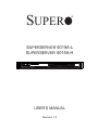
SUPERSERVER 5015A-L
SUPERSERVER 5015A-H
USER’S MANUAL
Revision 1.0
The information in this User’s Manual has been carefully reviewed and is believed to be accurate.
The vendor assumes no responsibility for any inaccuracies that may be contained in this document,
makes no commitment to update or to keep current the information in this manual, or to notify any
person or organization of the updates. Please Note: For the most up-to-date version of this
manual, please see our web site at www.supermicro.com.
Super Micro Computer, Inc. ("Supermicro") reserves the right to make changes to the product
described in this manual at any time and without notice. This product, including software, if any,
and documentation may not, in whole or in part, be copied, photocopied, reproduced, translated or
reduced to any medium or machine without prior written consent.
IN NO EVENT WILL SUPERMICRO BE LIABLE FOR DIRECT, INDIRECT, SPECIAL, INCIDENTAL,
SPECULATIVE OR CONSEQUENTIAL DAMAGES ARISING FROM THE USE OR INABILITY TO
USE THIS PRODUCT OR DOCUMENTATION, EVEN IF ADVISED OF THE POSSIBILITY OF
SUCH DAMAGES. IN PARTICULAR, SUPERMICRO SHALL NOT HAVE LIABILITY FOR ANY
HARDWARE, SOFTWARE, OR DATA STORED OR USED WITH THE PRODUCT, INCLUDING THE
COSTS OF REPAIRING, REPLACING, INTEGRATING, INSTALLING OR RECOVERING SUCH
HARDWARE, SOFTWARE, OR DATA.
Any disputes arising between manufacturer and customer shall be governed by the laws of Santa
Clara County in the State of California, USA. The State of California, County of Santa Clara shall
be the exclusive venue for the resolution of any such disputes. Super Micro's total liability for
all claims will not exceed the price paid for the hardware product.
FCC Statement: This equipment has been tested and found to comply with the limits for a Class
A digital device pursuant to Part 15 of the FCC Rules. These limits are designed to provide
reasonable protection against harmful interference when the equipment is operated in a commercial
environment. This equipment generates, uses, and can radiate radio frequency energy and, if not
installed and used in accordance with the manufacturer’s instruction manual, may cause harmful
interference with radio communications. Operation of this equipment in a residential area is likely
to cause harmful interference, in which case you will be required to correct the interference at your
own expense.
California Best Management Practices Regulations for Perchlorate Materials: This Perchlorate
warning applies only to products containing CR (Manganese Dioxide) Lithium coin cells. “Perchlorate
Material-special handling may apply. See www.dtsc.ca.gov/hazardouswaste/perchlorate”
WARNING: Handling of lead solder materials used in this
product may expose you to lead, a chemical known to
the State of California to cause birth defects and other
reproductive harm.
Manual Revision 1.0
Release Date: June 3, 2009
Unless you request and receive written permission from Super Micro Computer, Inc., you may not
copy any part of this document.
Information in this document is subject to change without notice. Other products and companies
referred to herein are trademarks or registered trademarks of their respective companies or mark
holders.
Copyright © 2009 by Super Micro Computer, Inc.
All rights reserved.
Printed in the United States of America
Preface
Preface
About This Manual
This manual is written for professional system integrators and PC technicians.
It provides information for the installation and use of the SuperServer 5015AL/5015A-H. Installation and maintainance should be performed by experienced
technicians only.
The SuperServer 5015A-L/5015A-H is a single processor 1U mini rackmount
server based on the SC502L-200B server chassis and the Intel® Atom™ X7SLA-L/
X7SLA-H motherboard.
Manual Organization
Chapter 1: Introduction
The first chapter provides a checklist of the main components included with the
server system and describes the main features of the Super X7SLA-L/X7SLA-H
motherboard and the SC502L-260B chassis.
Chapter 2: Server Installation
This chapter describes the steps necessary to install the SuperServer 5015AL/5015A-H into a rack and check out the server configuration prior to powering
up the system. If your server was ordered without the processor and memory
components, this chapter will refer you to the appropriate sections of the manual
for their installation.
Chapter 3: System Interface
Refer to this chapter for details on the system interface, which includes the functions
and information provided by the control panel on the chassis as well as other LEDs
located throughout the system.
iii
SUPERSERVER 5015A-L/5015A-H User's Manual
Chapter 4: System Safety
You should thoroughly familiarize yourself with this chapter for a general overview
of safety precautions that should be followed when installing and servicing the
SuperServer 5015A-L/5015A-H.
Chapter 5: Advanced Motherboard Setup
Chapter 5 provides detailed information on the X7SLA-L/X7SLA-H motherboard,
including the locations and functions of connectors, headers and jumpers. Refer
to this chapter when adding or removing processors or main memory and when
reconfiguring the motherboard.
Chapter 6: Advanced Chassis Setup
Refer to Chapter 6 for detailed information on the SC502L-200B 1U rackmount
server chassis. You should follow the procedures given in this chapter when installing, removing or reconfiguring drives and when replacing system power supply
units and cooling fans.
Chapter 7: BIOS
The BIOS chapter includes an introduction to BIOS and provides detailed information on running the CMOS Setup Utility.
Appendix A: POST Error Beep Codes
Appendix B: Installing Windows
Appendix C: System Specifications
iv
Preface
Notes
v
SUPERSERVER 5015A-L/5015A-H User's Manual
Table of Contents
Chapter 1 Introduction
1-1
Overview ......................................................................................................... 1-1
1-2
Motherboard Features ..................................................................................... 1-2
Processor ........................................................................................................ 1-2
Memory ........................................................................................................... 1-2
Onboard SATA................................................................................................. 1-2
PCI Expansion Slots ....................................................................................... 1-2
Onboard Controllers/Ports .............................................................................. 1-2
1-3
Server Chassis Features ................................................................................ 1-4
System Power ................................................................................................. 1-4
SATA Subsystem ............................................................................................. 1-4
Control Panel .................................................................................................. 1-4
Rear I/O Panel ................................................................................................ 1-4
Expansions Cards ........................................................................................... 1-4
1-4
Contacting Supermicro .................................................................................... 1-5
Chapter 2 Server Installation
2-2
Unpacking the System .................................................................................... 2-1
2-3
Preparing for Setup ......................................................................................... 2-1
Choosing a Setup Location ............................................................................. 2-1
Rack Mounting Considerations ....................................................................... 2-3
Ambient Operating Temperature ................................................................ 2-3
Reduced Airflow ......................................................................................... 2-3
Mechanical Loading ................................................................................... 2-3
2-4
Rack Mounting Instructions ............................................................................. 2-4
2-5
Checking the Motherboard Setup ................................................................... 2-6
2-6
Checking the Drive Bay Setup ........................................................................ 2-8
Chapter 3 System Interface
3-1
Overview ......................................................................................................... 3-1
3-2
Control Panel Buttons ..................................................................................... 3-1
Reset Button ................................................................................................... 3-1
Power .............................................................................................................. 3-1
3-3
Control Panel LEDs ........................................................................................ 3-1
Overheat.......................................................................................................... 3-2
NIC2 ................................................................................................................ 3-2
NIC1 ................................................................................................................ 3-2
HDD................................................................................................................. 3-2
vi
Table of Contents
Power .............................................................................................................. 3-3
Chapter 4 System Safety
4-1
Electrical Safety Precautions .......................................................................... 4-1
4-2
General Safety Precautions ............................................................................ 4-2
4-3
ESD Precautions ............................................................................................. 4-3
4-4
Operating Precautions .................................................................................... 4-4
Chapter 5 Advanced Motherboard Setup
5-1
Handling the Motherboard .............................................................................. 5-1
Precautions ..................................................................................................... 5-1
Unpacking ....................................................................................................... 5-2
5-2
Motherboard Installation .................................................................................. 5-2
5-3
Connecting Cables .......................................................................................... 5-3
Connecting Data Cables ................................................................................. 5-3
Connecting Power Cables .............................................................................. 5-3
Connecting the Control Panel ......................................................................... 5-3
5-4
I/O Ports .......................................................................................................... 5-4
5-5
Onboard Processor ......................................................................................... 5-5
5-6 Installing Memory ................................................................................................. 5-5
DIMM Installation ............................................................................................ 5-5
Memory Support .............................................................................................. 5-5
5-7
Adding PCI Expansion Cards ......................................................................... 5-7
5-8
Motherboard Details ........................................................................................ 5-8
X7SLA-L/X7SLA-H Quick Reference .............................................................. 5-9
5-9
Connector Definitions ................................................................................... 5-10
Main ATX Power Supply Connector ......................................................... 5-10
External Power Connector ...................................................................... 5-10
Power Button ............................................................................................ 5-10
Reset Button............................................................................................. 5-10
Power Fail LED ........................................................................................5-11
Overheat/Fan Fail......................................................................................5-11
NIC2 (LAN2) LED ......................................................................................5-11
NIC1 (LAN1) LED ......................................................................................5-11
HDD LED Switch .......................................................................................5-11
Power On LED ......................................................................................... 5-12
Fan Headers............................................................................................. 5-12
ATX PS/2 Keyboard and PS/2 Mouse Ports ............................................ 5-12
Serial Ports ............................................................................................... 5-12
Chassis Intrusion ...................................................................................... 5-13
vii
SUPERSERVER 5015A-L/5015A-H User's Manual
LAN1/2 (Ethernet Ports) .......................................................................... 5-13
Universal Serial Bus (USB) ...................................................................... 5-13
5-10
Jumper Settings ............................................................................................ 5-14
Explanation of Jumpers ............................................................................ 5-14
CMOS Clear ............................................................................................. 5-14
LAN1/2 Enable/Disable ........................................................................... 5-14
5-11
Onboard Indicators........................................................................................ 5-15
LAN1/2 LEDs............................................................................................ 5-15
5-12
IDE and SATA Ports ...................................................................................... 5-16
IDE Connector .......................................................................................... 5-16
SATA Ports ............................................................................................... 5-16
5-13
Installing Software ......................................................................................... 5-17
Supero Doctor III ........................................................................................... 5-18
Chapter 6 Advanced Chassis Setup
6-1
Static-Sensitive Devices .................................................................................. 6-1
Precautions ..................................................................................................... 6-1
Unpacking ............................................................................................................
6-2
Control Panel .................................................................................................. 6-2
6-3
System Fans ................................................................................................... 6-3
6-4
Drive Bay Installation/Removal ....................................................................... 6-3
Chapter 7 BIOS
7-1
Introduction...................................................................................................... 7-1
Starting BIOS Setup Utility .............................................................................. 7-1
How To Change the Configuration Data ......................................................... 7-1
Starting the Setup Utility ................................................................................. 7-2
7-2
Main Setup ...................................................................................................... 7-2
7-3
Advanced Setup Configurations...................................................................... 7-4
7-4
Security Settings ........................................................................................... 7-16
7-5
Boot Configuration .........................................................................................7-17
7-6
Exit Options ................................................................................................... 7-18
Appendix A POST Error Beep Codes
Appendix B Installing Windows
Appendix C System Specifications
viii
Chapter 1: Introduction
Chapter 1
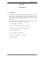
Introduction
1-1
Overview
The Supermicro SuperServer 5015A-L/5015A-H is a single processor, 1U rackmount
server. The 5015A-L/5015A-H is comprised of two main subsystems: the SC502L200B chassis and the X7SLA-L/X7SLA-H motherboard. Please refer to our web
site for information on operating systems that have been certified for use with the
5015A-L/5015A-H.
In addition to the mainboard and chassis, various hardware components may have
been included with the 5015A-L/5015A-H, as listed below.
•
One CPU heatsink (SNK-P0032A4)
•
One single 2.5" fixed HDD bracket (MCP-220-00051-0N)
•
One dual 2.5" fixed HDD bracket (MCP-220-00044-0N)
•
One SATA cable (CBL-0061L)
•
One CD containing drivers and utilities
•
SuperServer 5015A-L/5015A-H User's Manual
Note: "B" indicates black.
1-1
SUPERSERVER 5015A-L/5015A-H User's Manual
1-2
Motherboard Features
At the heart of the SuperServer 5015A-L/5015A-H lies the X7SLA-L/X7SLA-H, a
single processor, low-power motherboard based upon Intel's 945GC chipset. Below
are the main features of the X7SLA-L/X7SLA-H.
Processor
The X7SLA-H supports one Intel® Atom™ 330 Dual-core 1.6 GHz processor while
the X7SLA-L supports one Intel® Atom™ 230 Single-core 1.6 GHz processor. The
processors are embedded into the motherboard.
Memory
The X7SLA-L/X7SLA-H has two 240-pin DIMM slots that can support up to 2 GB
of non-ECC DDR2-533/400 SDRAM.
Onboard SATA
A SATA controller is built in to the ICH7R portion of the chipset to provide support
for a four port, 3 Gb/sec Serial ATA subsystem.
PCI Expansion Slots
The X7SLA-L/X7SLA-H has one PCI-Express x8 slot, one PCI-Express x4 (in a x8
slot) and one 32-bit PCI slot.
Onboard Controllers/Ports
An onboard IDE controller supports two IDE devices. Onboard I/O backpanel ports
include one COM port, a VGA port, PS/2 mouse and keyboard ports, a Gb LAN port
and two USB ports. In additiona, the X7SLA-H features two Gb LAN ports and an
extra internal COM port (header).
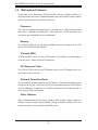
Other Features
Other onboard features that promote system health include voltage monitors, a
chassis intrusion header, auto-switching voltage regulators, chassis and CPU
overheat sensors, virus protection and BIOS rescue.
1-2
Chapter 1: Introduction
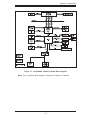
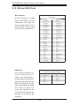
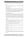
Figure 1-1. Intel 945GC Chipset: System Block Diagram
Note: This is a general block diagram. Please see Chapter 5 for details.
1-3
SUPERSERVER 5015A-L/5015A-H User's Manual
1-3
Server Chassis Features
The following is a general outline of the main features of the SC502L-200B 1U mini
rackmount server chassis.
System Power
The SC502L-200B chassis includes a single 200W power supply.
SATA Subsystem
The SC502L-200B chassis was designed to support one 3.5" or two 2.5" internal
SATA drives (not hot-swappable). ATA/100 IDE drives can be alternately supported.
Note: The operating system you use must have RAID support to enable the hotswap capability of the SATA drives (RAID 0, 1, 5 and 10 supported).
Control Panel
The control panel on the SC502L-200B provides important system monitoring and
control information. LEDs indicate power on, network activity, hard disk drive activity
and system overheat. The control panel also includes a main power button and a
system reset button as well as two
Rear I/O Panel
The rear I/O panel on the SC502L-200B provides one COM port, two USB ports,
PS/2 mouse and keyboard ports, a graphics port and two Gb Ethernet ports (one
on the 5015A-L).
Expansions Cards
The SC502L-200B supports the use of one full-height, half length PCI expansion
card.
1-4
Chapter 1: Introduction
1-4
Contacting Supermicro
Headquarters
Address:
Super Micro Computer, Inc.
980 Rock Ave.
San Jose, CA 95131 U.S.A.
Tel:
+1 (408) 503-8000
Fax:
+1 (408) 503-8008
Email:
[email protected] (General Information)
[email protected] (Technical Support)
Web Site:
www.supermicro.com
Europe
Address:
Super Micro Computer B.V.
Het Sterrenbeeld 28, 5215 ML
's-Hertogenbosch, The Netherlands
Tel:
+31 (0) 73-6400390
Fax:
+31 (0) 73-6416525
Email:
[email protected] (General Information)
[email protected] (Technical Support)
[email protected] (Customer Support)
Asia-Pacific
Address:
Super Micro Computer, Inc.
4F, No. 232-1, Liancheng Rd.
Chung-Ho 235, Taipei County
Taiwan, R.O.C.
Tel:
+886-(2) 8226-3990
Fax:
+886-(2) 8226-3991
Web Site:
www.supermicro.com.tw
Technical Support:
Email:
[email protected]
Tel:
886-2-8228-1366, ext.132 or 139
1-5
SUPERSERVER 5015A-L/5015A-H User's Manual
Notes
1-6
Chapter 2: Server Installation
Chapter 2
Server Installation
2-1
Overview
This chapter provides a quick setup checklist to get your SuperServer 5015AL/5015A-H up and running. Following the steps in the order given should enable
you to have the system operational within a minimal amount of time. This quick
setup assumes that your 5015A-L/5015A-H system has come to you with the processor and memory preinstalled. If your system is not already fully integrated with a
motherboard, processor, system memory etc., please turn to the chapter or section
noted in each step for details on installing specific components.
2-2
Unpacking the System
You should inspect the box the SuperServer 5015A-L/5015A-H was shipped in and
note if it was damaged in any way. If the server itself shows damage, you should
file a damage claim with the carrier who delivered it.
Decide on a suitable location for the rack unit that will hold the SuperServer 5015AL/5015A-H. It should be situated in a clean, dust-free area that is well ventilated.
Avoid areas where heat, electrical noise and electromagnetic fields are generated.
You will also need it placed near a grounded power outlet. Read the Rack and
Server Precautions in the next section.
2-3
Preparing for Setup
The box your chassis was shipped in should include four mounting screws, which
you will need if you intend to install the system into a rack. Please read this section
in its entirety before you begin the installation procedure outlined in the sections
that follow.
Choosing a Setup Location
•
•
Leave enough clearance in front of the rack to enable you to open the front
door completely (~25 inches).
Leave approximately 30 inches of clearance in the back of the rack to allow for
sufficient airflow and ease in servicing.
2-1
SUPERSERVER 5015A-L/5015A-H User's Manual
•
This product is for installation only in a Restricted Access Location (dedicated
equipment rooms, service closets, etc.).
•
This product is not suitable for use with visual display work place devices according to §2 of the the German Ordinance for Work with Visual Display Units.
!
Warnings and Precautions!
!
Rack Precautions
•
Ensure that the leveling jacks on the bottom of the rack are fully extended to
the floor with the full weight of the rack resting on them.
•
In a single rack installation, stabilizers should be attached to the rack.
•
In multiple rack installations, the racks should be coupled together.
•
Always make sure the rack is stable before extending a component from the
rack.
•
You should extend only one component at a time - extending two or more simultaneously may cause the rack to become unstable.
Server Precautions
•
•
•
Review the electrical and general safety precautions in Chapter 4.
Determine the placement of each component in the rack before you install the
rails.
Install the heaviest server components on the bottom of the rack first, and then
work up.
•
Use a regulating uninterruptible power supply (UPS) to protect the server from
power surges, voltage spikes and to keep your system operating in case of a
power failure.
•
Allow the power supply units and hot plug Serial ATA drives to cool before
touching them.
2-2
Chapter 2: Server Installation
•
Always keep the rack's front door and all panels and components on the servers
closed when not servicing to maintain proper cooling.
Rack Mounting Considerations
Ambient Operating Temperature
If installed in a closed or multi-unit rack assembly, the ambient operating temperature of the rack environment may be greater than the ambient temperature of the
room. Therefore, consideration should be given to installing the equipment in an
environment compatible with the manufacturer’s maximum rated ambient temperature (Tmra).
Reduced Airflow
Equipment should be mounted into a rack so that the amount of airflow required
for safe operation is not compromised.
Mechanical Loading
Equipment should be mounted into a rack so that a hazardous condition does not
arise due to uneven mechanical loading.
Circuit Overloading
Consideration should be given to the connection of the equipment to the power
supply circuitry and the effect that any possible overloading of circuits might have
on overcurrent protection and power supply wiring. Appropriate consideration of
equipment nameplate ratings should be used when addressing this concern.
Reliable Ground
A reliable ground must be maintained at all times. To ensure this, the rack itself
should be grounded. Particular attention should be given to power supply connections other than the direct connections to the branch circuit (i.e. the use of power
strips, etc.).
2-3
SUPERSERVER 5015A-L/5015A-H User's Manual
2-4
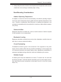
Rack Mounting Instructions
This section provides information on installing the SC502 chassis into a rack unit
There are a variety of rack units on the market, which may mean the assembly
procedure will differ slightly. You should also refer to the installation instructions that
came with the rack unit you are using.
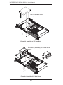
Installing the Chassis into a Rack
1. Confirm that chassis includes the four mounting screws required to mount the
chassis into a rack
2. Align the thru holes of the chassis with the thru holes of the rack.
3. Insert the mounting screws into the thru holes in the front of the chassis and
through the thru holes in the rack
Figure 2-1. Installing the Chassis into a Rack
2-4
Chapter 2: Server Installation
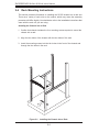
Installing into a Telco Rack
The SC502 supports Telco Rack installation. The SC502 chassis compact design
allows the chassis to be installed into a Telco rack without the use of rails.
Installing the Chassis into a Telco Rack
1. Confirm that chassis includes the four mounting screws required to mount the
chassis into a rack
2. Align the thru holes of the chassis with the thru holes of the rack.
3. Insert the mounting screws into the thru holes in the front of the chassis and
through the thru holes in the rack
Figure 2-2. Installing the Chassis into a Telco Rack
2-5
SUPERSERVER 5015A-L/5015A-H User's Manual
2-5
Checking the Motherboard Setup
After you install the 5015A-L/5015A-H in the rack, you will need to open the unit
to make sure the motherboard is properly installed and all the connections have
been made.
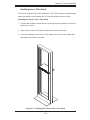
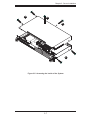
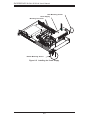
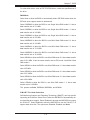
Accessing the Inside of the System (Figure 2-5)
1. First, grasp the two handles on either side and pull the unit straight out until it
locks (you will hear a "click").
2. Remove the five screws that hold the chassis cover in place.There are two
screws on each side of the chassis, and one screw on the back.
3. Once the screws have been removed, lift the cover upward to remove it from
the chassis.
Checking the Components
4. Your 5015A-L/5015A-H server system may have come with system memory
already installed. Make sure all DIMMs are fully seated in their slots. For
details on adding system memory, refer to Chapter 5.
5. If desired, you can install an add-on card to the system. See Chapter 5 for
details on installing a PCI add-on card.
6. Make sure all power and data cables are properly connected and not blocking
the airflow. See Chapter 5 for details on cable connections.
!
Warning: Except for short periods of time, do NOT operate the server
without the cover in place. The chassis cover must be in place to allow
proper airflow and prevent overheating.
2-6
Chapter 2: Server Installation
12
13
12
12
Figure 2-5. Accessing the Inside of the System
2-7
SUPERSERVER 5015A-L/5015A-H User's Manual
2-6
Checking the Drive Bay Setup
Next, you should check to make sure the drives have been properly installed and
all essential connections have been made.
Checking the Drives
1. Refer to Chapter 6 if you need to reinstall a DVD-ROM drive to the system.
2. Depending upon your system's configuration, your system may have one or
two Serial ATA drives already installed. If you need to install Serial ATA drives,
please refer to the appropriate section in Chapter 6.
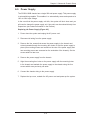
Providing Power
1. The last thing you must do is to provide input power to the system. Plug the
power cord from the power supply unit into a high-quality power strip that offers protection from electrical noise and power surges. It is recommended that
you use an uninterruptible power supply (UPS).
2. Finish by depressing the power button on the chassis control panel.
2-8
Chapter 3: System Interface
Chapter 3
System Interface
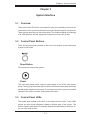
3-1
Overview
There are several LEDs on the control panel to keep you constantly informed of the
overall status of the system as well as the activity and health of specific components.
There are also two buttons on the control panel. This chapter explains the meanings
of all LED indicators and the appropriate response you may need to take.
3-2
Control Panel Buttons
There are two push buttons located on the front of the chassis: a reset button and
a power on/off button.
Reset Button
The reset button reboots the system.
Power
This is the main power button, which is used to apply or turn off the main system
power. Turning off system power with this button removes the main power but keeps
standby power supplied to the system. If you need to service the system you should
unplug the AC power cord after shutting down the server.
3-3
Control Panel LEDs
The control panel located on the front of the chassis has five LEDs. These LEDs
provide you with critical information related to different parts of the system. This
section explains what each LED indicates when illuminated and any corrective action you may need to take.
3-1
SUPERSERVER 5015A-L/5015A-H User's Manual
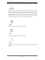
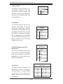
Overheat
When this LED is on it indicates an overheat condition, which may be caused by
cables obstructing the airflow in the system or the ambient room temperature being
too warm. Check the routing of the cables and make sure all fans are present and
operating normally. You should also check to make sure that the chassis covers
are installed. Finally, verify that the heatsinks are installed properly (see Chapter
5). This LED will remain on as long as the indicated condition exists.
2
NIC2
Indicates network activity on LAN2 when flashing .
1
NIC1
Indicates network activity on LAN1 when flashing.
HDD
Channel activity for all HDDs. This light indicates IDE or SATA drive activity when
flashing.
3-2
Chapter 3: System Interface
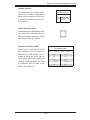
Power
Indicates power is being supplied to the system's power supply units. This LED
should normally be illuminated when the system is operating.
3-3
SUPERSERVER 5015A-L/5015A-H User's Manual
Notes
3-4
Chapter 4: System Safety
Chapter 4
System Safety
4-1
Electrical Safety Precautions
!
Basic electrical safety precautions should be followed to protect yourself from harm
and the SuperServer 5015A-L/5015A-H from damage:
•
Be aware of the locations of the power on/off switch on the chassis as well
as the room's emergency power-off switch, disconnection switch or electrical
outlet. If an electrical accident occurs, you can then quickly remove power from
the system.
•
•
•
Do not work alone when working with high voltage components.
Power should always be disconnected from the system when removing or installing main system components, such as the motherboard, memory modules
and floppy drive. When disconnecting power, you should first power down the
system with the operating system first and then unplug the power cords of all
the power supply units in the system.
When working around exposed electrical circuits, another person who is familiar
with the power-off controls should be nearby to switch off the power if necessary.
•
Use only one hand when working with powered-on electrical equipment. This
is to avoid making a complete circuit, which will cause electrical shock. Use
extreme caution when using metal tools, which can easily damage any electrical
components or circuit boards they come into contact with.
•
Do not use mats designed to decrease static electrical discharge as protection
from electrical shock. Instead, use rubber mats that have been specifically
designed as electrical insulators.
•
The power supply power cords must include a grounding plug and must be
plugged into grounded electrical outlets.
4-1
SUPERSERVER 5015A-L/5015A-H User's Manual
•
Motherboard Battery: CAUTION - There is a danger of explosion if the onboard
battery is installed upside down, which will reverse its polarites (see Figure
4-1). This battery must be replaced only with the same or an equivalent type
recommended by the manufacturer. Dispose of used batteries according to the
manufacturer's instructions.
•
DVD-ROM Laser: CAUTION - this server may have come equipped with a
DVD-ROM drive. To prevent direct exposure to the laser beam and hazardous
radiation exposure, do not open the enclosure or use the unit in any unconventional way.
•
Mainboard replaceable soldered-in fuses: Self-resetting PTC (Positive Temperature Coefficient) fuses on the mainboard must be replaced by trained service
technicians only. The new fuse must be the same or equivalent as the one
replaced. Contact technical support for details and support.
4-2
General Safety Precautions
!
Follow these rules to ensure general safety:
•
Keep the area around the 5015A-L/5015A-H clean and free of clutter.
•
The 5015A-L/5015A-H weighs approximately 10 lbs (4.5 kg). When lifting the
system, two people at either end should lift slowly with their feet spread out to
distribute the weight. Always keep your back straight and lift with your legs.
•
Place the chassis top cover and any system components that have been removed away from the system or on a table so that they won't accidentally be
stepped on.
•
While working on the system, do not wear loose clothing such as neckties and
unbuttoned shirt sleeves, which can come into contact with electrical circuits or
be pulled into a cooling fan.
•
Remove any jewelry or metal objects from your body, which are excellent metal
conductors that can create short circuits and harm you if they come into contact
with printed circuit boards or areas where power is present.
4-2
Chapter 4: System Safety
•
After accessing the inside of the system, close the system back up and secure
it to the rack unit with the retention screws after ensuring that all connections
have been made.
4-3
ESD Precautions
!
Electrostatic Discharge (ESD) is generated by two objects with different electrical
charges coming into contact with each other. An electrical discharge is created to
neutralize this difference, which can damage electronic components and printed
circuit boards. The following measures are generally sufficient to neutralize this
difference before contact is made to protect your equipment from ESD:
•
Use a grounded wrist strap designed to prevent static discharge.
•
Keep all components and printed circuit boards (PCBs) in their antistatic bags
until ready for use.
•
Touch a grounded metal object before removing the board from the antistatic
bag.
•
Do not let components or PCBs come into contact with your clothing, which may
retain a charge even if you are wearing a wrist strap.
•
Handle a board by its edges only; do not touch its components, peripheral chips,
memory modules or contacts.
•
When handling chips or modules, avoid touching their pins.
•
Put the motherboard and peripherals back into their antistatic bags when not
in use.
•
For grounding purposes, make sure your computer chassis provides excellent
conductivity between the power supply, the case, the mounting fasteners and
the motherboard.
4-3
SUPERSERVER 5015A-L/5015A-H User's Manual
4-4
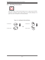
Operating Precautions
!
Care must be taken to assure that the chassis cover is in place when the 5015AL/5015A-H is operating to assure proper cooling. Out of warranty damage to the
system can occur if this practice is not strictly followed.
Figure 4-1. Installing the Onboard Battery
LITHIUM BATTERY
LITHIUM BATTERY
OR
BATTERY HOLDER
BATTERY HOLDER
4-4
Chapter 5: Advanced Motherboard Setup
Chapter 5
Advanced Motherboard Setup
This chapter covers the steps required to install the X7SLA-L/X7SLA-H motherboard
into the chassis, connect the data and power cables and install add-on cards. All
motherboard jumpers and connections are also described. A layout and quick reference chart are included in this chapter for your reference. Remember to completely
close the chassis when you have finished working with the motherboard to better
cool and protect the system.
5-1
Handling the Motherboard
Electrostatic Discharge (ESD) can damage electronic components. To prevent damage to any printed circuit boards (PCBs), it is important to handle them very carefully
(see previous chapter). To prevent the motherboard from bending, keep one hand
under the center of the board to support it when handling. The following measures
are generally sufficient to protect your equipment from electric static discharge.
Precautions
•
Use a grounded wrist strap designed to prevent Electrostatic Discharge
(ESD).
•
Touch a grounded metal object before removing any board from its antistatic
bag.
•
Handle a board by its edges only; do not touch its components, peripheral chips,
memory modules or gold contacts.
•
When handling chips or modules, avoid touching their pins.
•
Put the motherboard, add-on cards and peripherals back into their antistatic
bags when not in use.
•
For grounding purposes, make sure your computer chassis provides excellent
conductivity between the power supply, the case, the mounting fasteners and
the motherboard.
5-1
SUPERSERVER 5015A-L/5015A-H User's Manual
Unpacking
The motherboard is shipped in antistatic packaging to avoid electrical static discharge. When unpacking the board, make sure the person handling it is static
protected.
5-2
Motherboard Installation
This section explains the first step of physically mounting the X7SLA-L/X7SLA-H
into the SC502L-200B chassis. Following the steps in the order given will eliminate
the most common problems encountered in such an installation. To remove the
motherboard, follow the procedure in reverse order.
Installing to the Chassis
1. Access the inside of the system by removing the screws from the top cover of
the chassis, then lift the cover off.
2. Make sure that the I/O ports on the motherboard align properly with their
respective holes in the I/O shield at the back of the chassis.
3. Carefully mount the motherboard to the motherboard tray by aligning the
board holes with the raised metal standoffs that are visible in the chassis.
4. Insert screws into all the mounting holes on your motherboard that line up
with the standoffs and tighten until snug (if you screw them in too tight, you
might strip the threads). Metal screws provide an electrical contact to the
motherboard ground to provide a continuous ground for the system.
5. Finish by replacing the top cover of the chassis.
Warning: To avoid damaging the motherboard and its components, do not apply
any force greater than 8 lbs. per square inch when installing a screw into a mounting hole.
5-2
Chapter 5: Advanced Motherboard Setup
5-3
Connecting Cables
Now that the motherboard is installed, the next step is to connect the cables to
the board. These include the data cables for the peripherals and control panel and
the power cables.
Connecting Data Cables
The cables used to transfer data from the peripheral devices have been carefully
routed to prevent them from blocking the flow of cooling air that moves through
the system from front to back. If you need to disconnect any of these cables, you
should take care to keep them routed as they were originally after reconnecting
them (make sure the red wires connect to the pin 1 locations). The following data
cables (with their locations noted) should be connected. (See the motherboard
layout for connector locations.)
•
Control Panel cable (JF1)
•
COM Port cable (COM2)
•
Front USB port cable (USB2/3)
Connecting Power Cables
The X7SLA-L/X7SLA-H has a 24-pin primary power supply connector (JPW1) for
connection to the ATX power supply. See Section 5-9 for power connector pin
definitions.
Connecting the Control Panel
JF1 contains header pins for various front control panel connectors. See Figure 5-1
for the pin locations of the various front control panel buttons and LED indicators.
All JF1 wires have been bundled into a single cable to simplify this connection. Make
sure the red wire plugs into pin 1 as marked on the board. The other end connects
to the Control Panel PCB board, located just behind the system status LEDs on
the chassis. See Chapter 5 for details and pin descriptions.
5-3
SUPERSERVER 5015A-L/5015A-H User's Manual
Figure 5-1. Control Panel Header Pins
16
15
ED Anode+
Power LED
HDD LED
LED Anode+
NIC1 LED
LED Anode+
NIC2 LED
LED Anode+
OH/Fan Fail LED
LED Anode+
X
X
Ground
Reset (Button)
Ground
Power (Button)
2
5-4
1
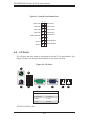
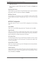
I/O Ports
The I/O ports are color coded in conformance with the PC 99 specification. See
Figure 5-2 below for the colors and locations of the various I/O ports.
Figure 5-2. I/O Ports
2
4
1
3
5
6
Rear I/O Ports
1. Keyboard
5. COM1
2. PS/2 Mouse
6. VGA Port
3. USB0
7. LAN1
4. USB1
8. LAN2*
*X7SLA-H (5015L-H) only.
5-4
7
8
Chapter 5: Advanced Motherboard Setup
5-5
Onboard Processor
The Intel Atom processor is soldered directly onto the motherboard. Installing and
removing the processor is not required. A small active heatsink (with fan) sits on
the processor to keep it cool.
5-6 Installing Memory
Note: Check the Supermicro web site for recommended memory modules.
CAUTION
Exercise extreme care when installing or removing DIMM
modules to prevent any possible damage.
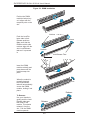
DIMM Installation
1. Insert the desired number of DIMMs into the memory slots, starting with
DIMM1A. Insert each DIMM vertically into its slot. Pay attention to the notch
along the bottom of the module to prevent incorrect installation.
2. Gently press down on the DIMM module until it snaps into place in the slot.
Repeat step 1 to install DIMM1B if needed. See diagrams on the following
page.
Memory Support
The X7SLA-L/X7SLA-H supports up to 2GB Unbuffered Non-ECC DDR2 533/400
in two DIMM slots. Populating these DIMM modules with a pair of memory modules of the same type and same size will result in interleaved memory, which will
improve memory performance.
5-5
SUPERSERVER 5015A-L/5015A-H User's Manual
Figure 5-3. DIMM Installation
Position the DIMM
module's bottom key
so it aligns with the
receptive point on the
slot.
Notches
Push the Lock/Release tabs to their
Release positions.
Make sure that the
DIMM module's side
notches align with the
slot's Lock/Release
tabs as it is pressed
in.
Release
Release
Lock/Release Tabs
Insert the DIMM
module vertically and
press down until the
module snaps into
place.
When the module is
properlly inserted,
the Lock/Release
tabs will automatically
secure the DIMM
module, locking it into
place.
Press Down
Lock
Lock
Release
To Remove:
Use your thumbs to
gently push the Lock/
Release tabs near
both ends of the
module. This should
release it from the
slot. Pull the DIMM
module upwards.
Release
5-6
Chapter 5: Advanced Motherboard Setup
5-7
Adding PCI Expansion Cards
The SC502L-200B chassis can accommodate one full-height, half-length PCI
expansion card.
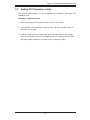
Installing an Expansion Card
1. After powering down the system, remove the PCI slot shield.
2. Fully seat the card into the slot, pushing down with your thumbs evenly on
both sides of the card.
3. Finish by using a screw to secure the top of the card shield to the chassis.
The PCI slot shield protects the motherboard and its components from EMI
and aid in proper ventilation, so make sure it is always in place.
5-7
SUPERSERVER 5015A-L/5015A-H User's Manual
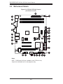
5-8
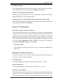
Motherboard Details
Figure 5-4. X7SLA-L/X7SLA-H Layout
(not drawn to scale)
JPW1
FAN1
26
KB/MOUSE
25
USB0/1
1
2
DIMM1B
COM1
DIMM1A
VGA
JF1
3
24
945GC
4
OH NIC NIC HDD PWR
LED
/FF
FAN_NB
FAN2
RST
JF1
1
JPL2
BT1
JPL1
IDE
JPL1-2:LAN1/2
1-2:ENABLE
2-3:DISABLE
20
19
I-SATA3
TP_ICH3
ICH7R
I-SATA2
J3
SLOT7 PCI-E X4 in X8
X7SLA-H
JBT1
JP5
JBT1:CMOS CLEAR
JP4
COM2
USB7
9
10
11
12
USB6
J51
J46
J13
USB4/5
USB2/3
13
14
JL1
FAN3
SLOT5 PCI 33MHZ
JPW2 for Device Power Only
15 16
Notes
USB 7, COM2 and LAN2 are available on the X7SLA-H only.
Jumpers not indicated are for test purposes only.
5-8
I-SATA1
I-SATA0
SLOT6 PCI-E X8
18
JL1:CHASSIS
INTRUSION
8
21
R52
R53
DESIGNED IN USA
7
FOR HOME OR OFFICE USE
Tested to Comply
6
With FCC Standards
LAN2
22
PWR ON
5
23
4
X
CPU
LAN1
1
17
Chapter 5: Advanced Motherboard Setup
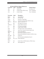
X7SLA-L/X7SLA-H Quick Reference
Connector
Label
Description
Default Setting
JBT1
#17
CMOS Clear
See Section 5-9
JPL2
#8
GLAN 2 Enable (X7SLA-H only)
Pins 1-2 (Enabled)
JPL1
#7
GLAN 1 Enable
Pins 1-2 (Enabled)
Connector
Label
Description
Battery
#21
Onboard Battery
BIOS
#19
SPI BIOS Chip
COM1
#3
Serial Port 1, Back Panel
COM2
#10
Serial Port 2 internal header (X7SLA-H only)
Fans 1~3
#9, 22, 25
System Cooling Fans 1~3
IDE
#20
IDE Hard Drive Connector
I-SATA 0~3
#18
Internal SATA Connectors
JF1
#24
FP Control Panel Header
JL1
#16
Chassis Intrusion Header
JPW1
#26
ATX 24-pin Power Connector (Required)
JPW2
#11
4-pin Power Connector (for device power only)
KB/Mouse
#1
PS/2 Keyboard/Mouse
LAN1
#5
Ethernet RJ45 (GB LAN) Connector 1
LAN2
#6
Ethernet RJ45 (GB LAN) Connector 2 (X7SLA-H only)
MCH FAN
#23
Chipset Fan
USB 0/1
#2
Back Panel Universal Serial Bus Ports 0/1
USB 2/3,
4/5, 6
#12, 13, 15
Internal USB Ports
USB 7
#14
Internal "Type A" USB Connector (X7SLA-H only)
VGA
#4
Video Graphics Port
5-9
SUPERSERVER 5015A-L/5015A-H User's Manual
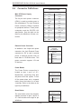
5-9
Connector Definitions
ATX Power 24-pin Connector
Pin Definitions (JPW1)
Pin#
Definition
Main ATX Power Supply
Connector
13
+3.3V
1
+3.3V
14
-12V
2
+3.3V
The 24-pin main power connector
15
COM
3
COM
(JPW1) is used to provide power to
16
PS_ON
4
+5V
the motherboard. The 4-pin External
Power connector (JPW2) is optional
17
COM
5
COM
18
COM
6
+5V
for peripheral devices. These power
19
COM
7
COM
connectors meet the SSI EPS 12V
20
Res (NC)
8
PWR_OK
21
+5V
9
5VSB
22
+5V
10
+12V
23
+5V
11
+12V
24
COM
12
+3.3V
specification. See the table on the
right for pin definitions of these connectors.
Pin #
Definition
Required Connection
External Power Connector
In addition to the 24-pin main power
connector, the 4-pin External Power
connector at JP3 is used to provide
power to external devices such as
hard disks & CD-ROM drives. This
power connector supports 12V and
5V devices.
4-Pin External Power
Connector
Pin Definitions
Pin
Definition
1
+12V
2
Ground 1
3
Ground 2
4
+5V
Optional Connection
Power Button
The Power Button connection is
located on pins 1 and 2 of JF1.
Momentarily contacting both pins
will power on/off the system. To turn
off the power when set to suspend
mode, press the button for at least
4 seconds. Refer to the table on the
right for pin definitions.
Reset Button
The reset button (from the computer
chassis) connects to pins 3 and 4 of
JF1. See the table on the right for pin
definitions.
5-10
Power Button
Pin Definitions (JF1)
Pin#
Definition
1
Power Signal
2
Ground
Reset Button
Pin Definitions (JF1)
Pin#
Definition
3
Reset
4
Ground
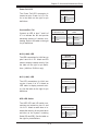
Chapter 5: Advanced Motherboard Setup
Power Fail LED
PWR Fail LED
Pin Definitions (JF1)
The Power Fail LED connection is
located on pins 5 and 6 of JF1. Refer to the table on the right for pin
definitions.
Overheat/Fan Fail
Connect an LED to pins 7 and 8 of
JF1 to indicate fan fail and provide
advanced warning of chassis overheating. Refer to the table on the right
for pin definitions.
Pin#
Definition
5
Vcc
6
Ground
OH/Fan Fail LED
Pin Definitions (JF1)
Pin#
Definition
OH/Fan Fail Indicator
Status
State
Definition
7
Vcc
Off
Normal
8
Ground
On
Overheat
Flashing
Fan Fail
NIC2 (LAN2) LED
The LED connections for LAN2 are on
pins 9 and 10 of JF1. Attach an LED
cable to display network activity. See
the table on the right for pin definitions. (LAN2 on 5015A-H only.)
NIC2 LED
Pin Definitions (JF1)
Pin#
Definition
9
Vcc
10
Ground
NIC1 (LAN1) LED
The LED connections for LAN1 are
on pins 11 and 12 of JF1. Attach an
LED cable to display network activity. See the table on the right for pin
definitions.
NIC1 LED
Pin Definitions (JF1)
Pin#
Definition
11
Vcc
12
Ground
HDD LED Switch
The HDD LED and UID switch connections are located on pins 13 and
14 of JF1. Attach a cable here to indicate disk activity (for any hard drive
activities on the system, including
Serial ATA and IDE). See the table on
the right for pin definitions.
5-11
HDD LED
Pin Definitions (JF1)
Pin#
Definition
13
Vcc
14
HD Active
SUPERSERVER 5015A-L/5015A-H User's Manual
Power On LED
Power LED
Pin Definitions (JF1)
The Power On LED connector is located on pins 15 and 16 of JF1. This
Pin#
Definition
connection is used to provide LED
15
5V Stby
indication of power being supplied to
16
Control
the system. See the table on the right
for pin definitions.
Fan Headers
The X7SLA-L/X7SLA-H has four fan
headers. Fan1~Fan3 are system
cooling fans. MCH_FAN is used for
the chipset fan. These fans are 4-pin
fan headers. However, Pins 1~3 of the
fan headers are backward compatible
with the traditional 3-pin fans. Note:
The 5015A-l/5015A-H does not is a
fan-less chassis so the FAN1~Fan3
headers are not used.
Fan Header
Pin Definitions
Pin#
Definition
1
Ground
2
+12V
3
Tachometer
4
PWM Control
PS/2 Keyboard and
Mouse Port Pin
Definitions (J28)
ATX PS/2 Keyboard and PS/2
Mouse Ports
The ATX PS/2 keyboard and the PS/2
mouse are located beside the USB0/1
ports. The mouse port is above the
keyboard port. See the table on the
right for pin definitions.
Pin#
Definition
1
Data
2
NC
3
Ground
4
VCC
5
Clock
6
NC
Serial Port Pin Definitions
(COM1/COM2)
Serial Ports
Pin #
Two serial ports are included on the
motherboard. COM1 is a backpanel
port and COM2 is a header located
on the corner of the board near
USB2. See the table on the right for
pin definitions.
5-12
Definition
Pin #
Definition
1
DCD
6
DSR
2
RXD
7
RTS
3
TXD
8
CTS
4
DTR
9
RI
5
Ground
10
NC
Chapter 5: Advanced Motherboard Setup
Chassis Intrusion
Chassis Intrusion
Pin Definitions (JL1)
The Chassis Intrusion header is designated JL1. Attach an appropriate
Pin#
Definition
cable from the chassis to inform you
1
Intrusion Input
of a chassis intrusion when the chas-
2
Ground
sis is opened
LAN1/2 (Ethernet Ports)
Two Ethernet ports (designated LAN1
and LAN2) are located beside the
VGA port on the I/O backplane. These
ports accept RJ45 type cables.
Universal Serial Bus (USB)
There are two Universal Serial Bus
ports located on the I/O panel. An
additional six USB headers are included on the board, which may be
used for front side access (cables not
included). USB 6 and USB 7 are "Type
A" connectors. See the table on the
right for pin definitions.
5-13
Universal Serial Bus
Pin Definitions (USB)
Pin #
USB0/1
Definition
USB4/5/6/7
Pin #
Definition
1
+5V
1
+5V
2
PO-
2
PO-
3
PO+
3
PO+
4
Ground
4
Ground
5
N/A
5
Key
SUPERSERVER 5015A-L/5015A-H User's Manual
5-10 Jumper Settings
Explanation of Jumpers
To modify the operation of the motherboard, jumpers can be used to choose
between optional settings. Jumpers
3
2
1
3
2
1
Connector
Pins
create shorts between two pins to
change the function of the connector.
Pin 1 is identified with a square solder
Jumper
pad on the printed circuit board. See
the motherboard layout pages for
jumper locations.
Setting
Note: On a two-pin jumper, "Closed"
means the jumper is on both pins and
"Open" means the jumper is either on
only one pin or completely removed.
CMOS Clear
JBT1 is used to clear CMOS (which will also clear any passwords). Instead of pins,
this jumper consists of contact pads to prevent accidentally clearing the contents
of CMOS.
To clear CMOS,
1. First power down the system and unplug the power cord(s).
2. With the power disconnected, short the CMOS pads with a metal object such
as a small screwdriver.
3. Remove the screwdriver (or shorting device).
4. Reconnect the power cord(s) and power on the system.
Note: Do not use the PW_ON connector to clear CMOS.
LAN1/2 Enable/Disable
Change the setting of jumper JPL1
and JPL2 to enable or disable the
LAN1 and LAN2 Ethernets ports, respectively. See the table on the right
for jumper settings. The default setting
is enabled.
5-14
LAN1/2 En/Disable Jumper Settings (JPL1/JPL2)
Jumper Setting
Definition
Pins 1-2
Enabled
Pins 2-3
Disabled
Chapter 5: Advanced Motherboard Setup
5-11 Onboard Indicators
LAN1/2 LED
(Connection Speed Indicator)
LAN1/2 LEDs
The Ethernet ports (located beside the
VGA port) have two LEDs. On each
port, one LED indicates activity while
the other LED may be green, amber
or off to indicate the speed of the
connection. See the table on the right
for the indication associated with the
connection speed LED.
5-15
LED Color
Definition
Off
No Connection or 10 Mb/s
Green
100 Mb/s
Amber
1 Gb/s
SUPERSERVER 5015A-L/5015A-H User's Manual
5-12 IDE and SATA Ports
IDE Connector
An IDE Connector is located
close to SATA Ports 0~3 on the
IDE Connector
Pin Definitions
Pin#
Definition
Pin #
Definition
1
Reset IDE
2
Ground
motherboard. This 40-pin con-
3
Host Data 7
4
Host Data 8
nector provides support for 3.5"
5
Host Data 6
6
Host Data 9
7
Host Data 5
8
Host Data 10
9
Host Data 4
10
Host Data 11
11
Host Data 3
12
Host Data 12
13
Host Data 2
14
Host Data 13
15
Host Data 1
16
Host Data 14
17
Host Data 0
18
Host Data 15
19
Ground
20
Key
21
DRQ3
22
Ground
23
I/O Write
24
Ground
25
I/O Read
26
Ground
27
SIORDY
28
(PD)
29
SDDACK#
30
Ground
31
IRQ15
32
(NC)
33
Addr1
34
SHDD66DET
35
Addr0
36
Addr2
37
SDCS1#
38
SDCS3#
39
SHDDLED#
40
Ground
hard drive disks. See the table
on the right for pin definitions.
SATA Ports
Four Serial ATA (SATA) connectors (I-SATA 0~3) are located on the motherboard to
provide serial link connections.
Serial Link connections provide
faster data transmission than
those of the traditional Parallel
ATA. These four SATA connectors are supported by the
Intel ICH7R South Bridge. See
the table on the right for pin
definitions.
SATA Port
Pin Definitions (I-SATA0, I-SATA5)
Pin#
Definition
1
Ground
2
TXP
3
TXN
4
Ground
5
RXN
6
RXP
7
Ground
5-16
Pin #
Definition
Chapter 5: Advanced Motherboard Setup
5-13 Installing Software
After the hardware has been installed, you should first install the operating system
and then the drivers. The necessary drivers are all included on the Supermicro CDs
that came packaged with your motherboard.
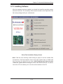
Driver/Tool Installation Display Screen
Note: Click the icons showing a hand writing on paper to view the readme files
for each item. Click the computer icons to the right of these items to install each
item (from top to the bottom) one at a time. After installing each item, you must
re-boot the system before moving on to the next item on the list. The bottom
icon with a CD on it allows you to view the entire contents of the CD.
5-17
SUPERSERVER 5015A-L/5015A-H User's Manual
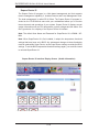
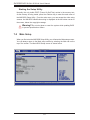
Supero Doctor III
The Supero Doctor III program is a Web based management tool that supports
remote management capability. It includes Remote and Local Management tools.
The local management is called SD III Client. The Supero Doctor III program included on the CD-ROM that came with your motherboard allows you to monitor
the environment and operations of your system. Supero Doctor III displays crucial
system information such as CPU temperature, system voltages and fan status. See
the Figure below for a display of the Supero Doctor III interface.
Note: The default User Name and Password for SuperDoctor III is ADMIN / ADMIN.
Note: When SuperDoctor III is first installed, it adopts the temperature threshold
settings that have been set in BIOS. Any subsequent changes to these thresholds
must be made within Super Doctor, as the Super Doctor settings override the BIOS
settings. To set the BIOS temperature threshold settings again, you would first need
to uninstall SuperDoctor III.
Supero Doctor III Interface Display Screen (Health Information)
5-18
Chapter 5: Advanced Motherboard Setup
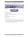
Supero Doctor III Interface Display Screen (Remote Control)
Note: SD III Software Revision 1.0 can be downloaded from our Web Site at: ftp://ftp.
supermicro.com/utility/Supero_Doctor_III/. You can also download the SDIII User's
Guide at: <http://www.supermicro.com/PRODUCT/Manuals/SDIII/UserGuide.pdf>.
For Linux, we will recommend using Supero Doctor II.
5-19
SUPERSERVER 5015A-L/5015A-H User's Manual
Notes
5-20
Chapter 6: Advanced Chassis Setup
Chapter 6
Advanced Chassis Setup
This chapter covers the steps required to install components and perform maintenance on the SC502L chassis. For component installation, follow the steps in
the order given to eliminate the most common problems encountered. If a step is
unnecessary, skip ahead to the step that follows.
Tools Required
The only tool you will need to install components and perform maintenance is a
Philips screwdriver.
6-1
Static-Sensitive Devices
Electrostatic Discharge (ESD) can damage electronic components. To prevent
damage to any printed circuit boards (PCBs), it is important to handle them very
carefully. The following measures are generally sufficient to protect your equipment
from ESD discharge.
Precautions
•
Use a grounded wrist strap designed to prevent static discharge.
•
Touch a grounded metal object before removing any board from its antistatic
bag.
•
Handle a board by its edges only; do not touch its components, peripheral chips,
memory modules or gold contacts.
•
•
•
When handling chips or modules, avoid touching their pins.
Put the serverboard, add-on cards and peripherals back into their antistatic
bags when not in use.
For grounding purposes, make sure your computer chassis provides excellent
conductivity between the power supply, the case, the mounting fasteners and
the serverboard.
6-1
SUPERSERVER 5015A-L/5015A-H User's Manual
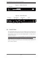
Figure 6-1. Chassis Front View
Control Panel
Figure 6-2. Chassis Rear View
Power Supply
Mouse/Keyboard
USB Ports
6-2
COM Port
Ethernet Ports
PCI Slot
VGA Port
Control Panel
The control panel (located on the front of the chassis) must be connected to the
JF1 connector on the serverboard to provide you with system control buttons and
status indicators. These wires have been bundled together in a ribbon cable to
simplify the connection.
Connect the cable from JF1 on the serverboard to the Control Panel PCB (printed
circuit board). Make sure the red wire plugs into pin 1 on both connectors. Pull all
excess cabling out of the airflow path. The LEDs inform you of system status. See
Chapter 3 for details on the LEDs and the control panel buttons. Details on JF1
can be found in Chapter 5.
6-2
Chapter 6: Advanced Chassis Setup
6-3
System Fans
The SC502L is a fan-less chassis, which results in extremely quiet and energyefficient operation. The only fan in the system is located on the heatsink for the
embedded processor.
6-4
Drive Bay Installation/Removal
Installling a 3.5" SATA Drive (Figure 6-3)
1. Power down the system and unplug the AC power cord.
2. Remove the chassis cover as described on page 2-6.
3. Use screws to secure the drive directly into the left side of the chassis as
shown in the figure.
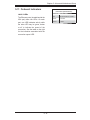
Installling 2.5" SATA Drives (Figure 6-4)
1. Power down the system and unplug the AC power cord.
2. Remove the chassis cover as described on page 2-6.
3. Use screws to secure the drive into the hard drive bracket:
For two drives the bracket is p/n MCP-220-00044-0N.
For one drive the bracket is p/n MCP-220-00051-0N.
4. Use screws to secure the bracket/drive assembly into the left side of the
chassis as shown in the figure.
6-3
SUPERSERVER 5015A-L/5015A-H User's Manual
The 3.5" hard drive screws
directly into the chassis
Figure 6-3. Installing a 3.5" Hard Drive
The 2.5" hard drives (1) must be installed in
the bracket (2) before they are screwed into the
chassis.
1
12
Figure 6-4. Installing 2.5" Hard Drives
6-4
Chapter 6: Advanced Chassis Setup
6-5
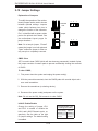
Power Supply
The SC502L-200B chassis has a single 200 watt power supply. This power supply
is auto-switching capable. This enables it to automatically sense and operate at a
100v to 240v input voltage.
In the event that the power supply unit fails, the system will shut down and you
will need to change the power supply unit. New units can be ordered directly from
Supermicro (see contact information in the Preface).
Replacing the Power Supply (Figure 6-5)
1. Power down the system and unplug the AC power cord.
2. Disconnect all wiring from the power supply.
3. Remove the four screws that secure the power supply to the chassis and
extend upwards through the mounting thru holes, to hold the power supply in
place (two mounting screws are located on the rear of the power supply and
two mounting screws are accessed on the underside of the chassis). Set the
screws aside for later use.
4. Remove the power supply from the chassis.
5. Align the mounting thru holes on the power supply with the mounting holes
in the chassis and reattach the power supply to the chassis using the four
screws which were previously set aside
6. Connect the chassis wiring to the power supply.
7. Replace the top cover, reattach the AC power cord and power up the system.
6-5
SUPERSERVER 5015A-L/5015A-H User's Manual
Rear Mounting Screws
Power Supply
Mounting Thru Holes
Bottom Mounting Screws
Figure 6-5. Installing the Power Supply
6-6
Chapter 7: BIOS
Chapter 7
BIOS
7-1
Introduction
This chapter describes the AMI BIOS Setup Utility for the X7SLA-L/X7SLA-H. The
AMI ROM BIOS is stored in a Flash EEPROM and can be easily updated. This chapter describes the basic navigation of the AMI BIOS Setup Utility setup screens.
Starting BIOS Setup Utility
To enter the AMI BIOS Setup Utility screens, press the <Delete> key while the
system is booting up.
Note: In most cases, the <Delete> key is used to invoke the AMI BIOS
setup screen. There are a few cases when other keys are used, such as
<F1>, <F2>, etc.
Each main BIOS menu option is described in this manual. The Main BIOS setup
menu screen has two main frames. The left frame displays all the options that can
be configured. Grayed-out options cannot be configured. Options in blue can be
configured by the user. The right frame displays the key legend. Above the key
legend is an area reserved for a text message. When an option is selected in the
left frame, it is highlighted in white. Often a text message will accompany it. (Note:
the AMI BIOS has default text messages built in. Supermicro retains the option to
include, omit, or change any of these text messages.)
The AMI BIOS Setup Utility uses a key-based navigation system called hot keys.
Most of the AMI BIOS setup utility hot keys can be used at any time during the
setup navigation process. These keys include <F1>, <F10>, <Enter>, <ESC>, arrow keys, etc.
Note: Options printed in Bold are default settings.
How To Change the Configuration Data
The configuration data that determines the system parameters may be changed by
entering the AMI BIOS Setup utility. This Setup utility can be accessed by pressing
<Del> during system boot.
7-1
SUPERSERVER 5015A-L/5015A-H User's Manual
Starting the Setup Utility
Normally, the only visible POST (Power On Self Test) routine is the memory test.
As the memory is being tested, press the <Delete> key to enter the main menu of
the AMI BIOS Setup Utility. From the main menu, you can access the other setup
screens. An AMI BIOS identification string is displayed at the left bottom corner of
the screen, below the copyright message.
Warning!!
Do not shut down or reset the system while updating BIOS
to prevent possible boot failure.
7-2
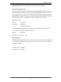
Main Setup
When you first enter the AMI BIOS Setup Utility, you will enter the Main setup screen.
You can always return to the Main setup screen by selecting the Main tab on the
top of the screen. The Main BIOS Setup screen is shown below.
BIOS SETUP UTILTY
Main
Advanced
Security
Boot
Exit
System Overview
System Time
System Date
Supermicro X7SLA
Version
: XX.XX.XX
Build Date : XX/XX/XX
ID
: X7SLA000
[HH
HH:MM:SS]
:MM:SS]
[Tue 04/24/2009]
Use [ENTER], [TAB]
or [SHIFT-TAB] to
select a field.
Use [+] or [-] to
configure system time.
Processor
Intel(R) Atom (TM) CPU 330 @ 1.60GHz
Speed
: 1600MHz
Physical Count / Logical Count
:1
: Move
Enter : Select
+/-/ : Value
F10 : Save
ESC : Exit
F1 : General Help
F8 : Fail-Safe Defaults
F9 : Optimized Defaults
System Memory
Available Size
: 2040MB
Populated Size : 2040MB
vXX.XX (C) Copyright 1985-2009, American Megatrends, Inc.
7-2
Chapter 7: BIOS
System Overview: The following BIOS information will be displayed:
System Time/System Date
Use this option to change the system time and date. Highlight System Time or System Date using the arrow keys. Enter new values through the keyboard. Press the
<Tab> key or the arrow keys to move between fields. The date must be entered in
Day MM/DD/YY format. The time is entered in HH:MM:SS format. (Note: The time
is in the 24-hour format. For example, 5:30 P.M. appears as 17:30:00.)
Supermicro X7SLA
Version
: XX.XX.XX
Build Date
: MM/DD/YY
ID
: XXXXXXXXProcessor
The AMI BIOS automatically displays the status of processor as shown below:
Intel (R) Atom (TM) CPU XXX @ XX.XXGHz
Speed
:XXXXMHz
Physical Count / Logical Count
:1
System Memory
Available Size displays the size of memory available in the system. Populated
Size displays the total size of memory detected in the system. Both are displayed
in Megabytes (MB).
Available Size :XXXXMB
Populated Size :XXXXMB
7-3
SUPERSERVER 5015A-L/5015A-H User's Manual
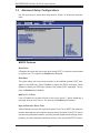
7-3
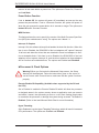
Advanced Setup Configurations
Use the arrow keys to select Boot Setup and hit <Enter> to access the submenu
items:
BIOS SETUP UTILTY
Main
Advanced
Security
Boot
Exit
Advanced Settings
WARNING: Setting the wrong values in the sections below
may cause the system to malfunction.
BIOS Features
Processor & Clock Options
Advanced Chipset Control
IDE Configuration
PCI/PnP Configuration
Super IO Device Configuration
Hardware Health Configuration
Remote Access Configuration
: Move
Enter : Select
+/-/ : Value
F10 : Save
ESC : Exit
F1 : General Help
F8 : Fail-Safe Defaults
F9 : Optimized Defaults
vXX.XX (C) Copyright 1985-2009, American Megatrends, Inc.
XBIOS Features
Quick Boot
If Enabled, this option will skip certain tests during POST to reduce the time needed
for system boot. The options are Enabled and Disabled.
Quiet Boot
This option allows the bootup screen options to be modified between POST messages or the OEM logo. Select Disabled to display the POST messages. Select
Enabled to display the OEM logo instead of the normal POST messages. The options are Enabled and Disabled.
Wait for ‘F1’ If Error
If set to Enabled, the system will wait for the user to press F1 before displaying a
message when an error occurs. The options are Enabled and Disabled.
High Performance Event Timer
Select Enabled to activate the High Performance Event Timer (HPET) that produces
periodic interrupts at a much higher frequency than a Real-time Clock (RTC) does in
synchronizing multimedia streams, providing smooth playback and reducing the dependency on other timestamp calculation devices, such as an x86 RDTSC Instruc-
7-4
Chapter 7: BIOS
tion embedded in the CPU. The High Performance Event Timer is used to replace
the 8254 Programmable Interval Timer. The options are Enabled and Disabled.
XACPI Configuration
Use this feature to configure ACPI (Advanced Configuration and Power Interface)
power management settings for your system.
ACPI Aware OS
Select Yes to enable ACPI support for the OS. Disable this feature if ACPI is not
supported by your OS. The options are Yes and No.
Suspend Mode
This option is used to select the ACPI State that is used for system suspend.
The options are S1 (POS), S3 (STR) and Auto.
S1 (POS) - All processor caches are erased, and stops executing instructions. Power to the CPU(s) and RAM is maintained, but RAM is
refreshed.
S3 (STR) - The CPU has no power and the power supply goes on reduced
power mode. However, main memory (RAM) is still powered.
ACPI Version Feature
This feature allows the user to select the ACPI Version for the system. The options are ACPI 1.0, ACPI 2.0, and ACPI 3.0.
USB Device Wakeup
Select Enable to "wake-up" the system via a USB device when the system is
in S3 or S4 State. The options are Enabled and Disabled.
PS2 KB/MS Wake Up
Select Enable to "wake-up" the system using either the PS2 keyboard or mouse
(if equipped) when the system is in S3 (Sleep) or S4 (Hibernate) state. The
options are Enabled and Disabled.
Watch Dog Function
Select Enable to enable Watch Dog Timer and allow the system to reboot when it
is inactive for more than 5 minutes. The options are Enabled and Disabled.
Restore on AC Power Loss
Use this feature to set the power state after a power outage. Select Power-Off for
the system power to remain off after a power loss. Select Power-On for the system
power to be turned on after a power loss. Select Last State to allow the system to
7-5
SUPERSERVER 5015A-L/5015A-H User's Manual
resume its last state before a power loss. The options are Power-On, Power-Off
and Last State.
Power Button Function
If set to Instant Off, the system will power off immediately as soon as the user
presses the power button. If set to 4 Seconds Override, the system will power off
when the user presses the power button for 4 seconds or longer. The options are
Instant Off and 4 Seconds Override.
MPS Revision
This feature allows the user to specify the version of the Multi-Processor Specification (MPS) the motherboard is using. The options are 1.4 and 1.1.
Interrupt 19 Capture
Interrupt 19 is the software interrupt that handles the boot disk function. When this
item is set to Enabled, the ROM BIOS of the host adaptors will "capture" Interrupt
19 at boot and allow the drives that are attached to these host adaptors to function as bootable disks. If this item is set to Disabled, the ROM BIOS of the host
adaptors will not capture Interrupt 19, and the drives attached to these adaptors
will not function as bootable devices. The options are Enabled and Disabled.
XProcessor & Clock Options
Warning! When you first enter the Advanced Setup screen, the Setup
Warning will be displayed. Follow the instructions given on the screen to
set the correct value for each item to make sure that the system functions
properly.
Execute-Disable Bit Capability (Available when supported by the OS and
the CPU)
Set to Enabled to enable the Execute Disable Bit which will allow the processor
to designate areas in the system memory where an application code can execute
and where it cannot, thus preventing a worm or a virus from flooding illegal codes
to overwhelm the processor or damage the system during an attack. The default is
Enabled. (Refer to Intel and Microsoft Web Sites for more information.)
Hyper-Threading
Set to Enabled to use the Hyper-Threading Technology, which will result in increased
CPU performance. The options are Disabled and Enabled.
7-6
Chapter 7: BIOS
XAdvanced Chipset Control
The items included in the Advanced Settings submenu are listed below:
XNorthBridge Configuration
This feature allows the user to configure the settings for the Intel 945GC NorthBridge.
DRAM Frequency
This feature allows the user to select the DRAM Frequency setting. The options
are Auto (Auto-detect), 400 MHz and 533 MHz.
Configure DRAM Timing by SPD
Select Enable to allow the BIOS to read the SPD (Serial Presence Detect) chip
which is built in the memory module in order to get the exact memory specifications. The options are Enabled and Disabled.
Memory Hole
Use the feature to allocate memory resource reserved for use of PCI devices. If
set to 15 MB~16MB, the reserved memory will be placed in the location around
15 MB~16 MB. The options are Disabled and 15 MB~ 16 MB.
Initiate Graphic Adapter
Use the feature to select the graphics controller to be used as the primary boot
device. The options are IGD, PCI/IGD, PCI/PEG, PEG/IGD, and PEG/PCI.
Internal Graphics Device Mode Select
Use the feature to set the amount of system memory to be used by the Internal
Graphics Devices. The options are Disabled, Enabled, 1 MB and Enabled, 8
MB.
PEG Port Configuration
PEG Port
Use the feature to configure the PEG Port. The Default setting is Auto to
allow the PEG Port to be automatically detected and configured by the BIOS.
The options are Auto and Disabled.
PEG Force x1
If set to Enabled, PEG will be configured to x1 setting by the BIOS. The
options are Enabled, and Disabled.
7-7
SUPERSERVER 5015A-L/5015A-H User's Manual
XVideo Function Configuration
DVMT Mode Select
This option allows the user to set the DVMT mode. The options are Fixed Mode,
DVMT Mode and the COMBO mode.
DVMT/Fixed Memory
This option allows the user to set the amount of memory to be used for
operation in the DVMT/Fixed Mode. The options are 64 MB, 128 MB and
Maximum DVMT.
Boot Display Device
This option allows the user to select the boot display device. The options are
CRT on Port 0, LFP on Port2, and CRT-Port 0 & LFP-Port 2.
USB Functions
This feature allows the user to enable or disable the onboard USB ports. The options are Disabled and Enabled.
USB 2.0 Controller
Select Enabled to activate the onboard USB 2.0 controller. The options are Enabled and Disabled.
XUSB Configuration
This feature allows the user to configure USB settings for the motherboard.
Legacy USB Support
Select Enabled to use Legacy USB devices. If this item is set to Auto, Legacy
USB support will be automatically enabled if a legacy USB device is installed
on the motherboard, and vise versa. The settings are Disabled, Enabled and
Auto.
USB 2.0 Controller Mode
This setting allows you to select the USB 2.0 Controller mode. The options are
Hi-Speed (480 Mbps) and Full Speed (12 Mbps).
BIOS EHCI Hand-Off
Select Enabled to enable BIOS Enhanced Host Controller Interface support to
provide a workaround solution for an operating system that does not have EHCI
Hand-Off support. When enabled, the EHCI Interface will be changed from the
BIOS-controlled to the OS-controlled. The options are Disabled and Enabled.
7-8
Chapter 7: BIOS
Clock-Spread Spectrum
Select Enable to use the feature of Clock Spectrum, which will allow the BIOS to
monitor and attempt to reduce the level of Electromagnetic Interference caused by
the components whenever needed. The options are Disabled and Enabled. If this
feature is set to Enabled, the following items will display:
XIDE Configuration
When this submenu is selected, the AMI BIOS automatically detects the presence
of the IDE Devices and displays the following items:
ATA/IDE Configuration
This feature allows the user to configure ATA/IDE settings. The options are Disabled
and Enhanced.
Configure SATA as
Please choose IDE if the installed hard disk(s) are to be configured as
independent devices and will be used normally.
Choose RAID if you have more than one drive installed and will be used in
a Redundant Array (RAID) configuration.
Note: Please use the Intel Matrix Storage Manager (option ROM) to configure your RAID by pressing and holding down <Ctrl> and pressing <I>
(the "i" key) during POST. For a downloadable PDF manual, please visit
Supermicro's website at: http://www.supermicro.com/support/manuals/ and
click "HostRAID - Setup for Intel ICH7R / ICH9R" under RAID Installation
Guides.
Select AHCI for advanced SATA features such as hot-plugging and native
command queueing. Note: Take caution when using AHCI, as your operating system may need drivers to match this configuration. This feature is for
technicians only.
The options are IDE, RAID and AHCI.
Configure SATA Channels
The options are Before PATA and Behind PATA.
Primary IDE Master/Slave, Secondary IDE Maser/Slave and Third IDE Maser/
Slave
These settings allow the user to set the parameters of Primary IDE Master/Slave,
Secondary IDE Master/Slave and Third IDE Master/Slave slots. Hit <Enter> to
7-9
SUPERSERVER 5015A-L/5015A-H User's Manual
activate the following submenu screen for detailed options of these items. Set the
correct configurations accordingly. The items included in the submenu are:
Type
Select the type of device connected to the system. The options are Not Installed,
Auto, CD/DVD and ARMD.
LBA/Large Mode
LBA (Logical Block Addressing) is a method of addressing data on a disk drive.
In the LBA mode, the maximum drive capacity is 137 GB. For drive capacities
over 137 GB, your system must be equipped with a 48-bit LBA mode addressing.
If not, contact your manufacturer or install an ATA/133 IDE controller card that
supports 48-bit LBA mode. The options are Disabled and Auto.
Block (Multi-Sector Transfer)
Block Mode boosts the IDE drive performance by increasing the amount of data
transferred. Only 512 bytes of data can be transferred per interrupt if Block Mode
is not used. Block Mode allows transfers of up to 64 KB per interrupt. Select
Disabled to allow data to be transferred from and to the device one sector at
a time. Select Auto to allow data transfer from and to the device occur multiple
sectors at a time if the device supports it. The options are Auto and Disabled.
PIO Mode
The IDE PIO (Programmable I/O) Mode programs timing cycles between the
IDE drive and the programmable IDE controller. As the PIO mode increases, the
cycle time decreases. The options are Auto, 0, 1, 2, 3, and 4.
Select Auto to allow the AMI BIOS to automatically detect the PIO mode. Use
this value if the IDE disk drive support cannot be determined.
Select 0 to allow the AMI BIOS to use PIO mode 0. It has a data transfer rate
of 3.3 MBs.
Select 1 to allow the AMI BIOS to use PIO mode 1. It has a data transfer rate
of 5.2 MBs.
Select 2 to allow the AMI BIOS to use PIO mode 2. It has a data transfer rate
of 8.3 MBs.
Select 3 to allow the AMI BIOS to use PIO mode 3. It has a data transfer rate
of 11.1 MBs.
Select 4 to allow the AMI BIOS to use PIO mode 4. It has a data transfer rate
of 16.6 MBs. This setting generally works with all hard disk drives manufactured
after 1999.
7-10
Chapter 7: BIOS
For other disk drives, such as IDE CD-ROM drives, check the specifications of
the drive.
DMA Mode
Select Auto to allow the BIOS to automatically detect IDE DMA mode when the
IDE disk drive support cannot be determined.
Select SWDMA0 to allow the BIOS to use Single Word DMA mode 0. It has a
data transfer rate of 2.1 MBs.
Select SWDMA1 to allow the BIOS to use Single Word DMA mode 1. It has a
data transfer rate of 4.2 MBs.
Select SWDMA2 to allow the BIOS to use Single Word DMA mode 2. It has a
data transfer rate of 8.3 MBs.
Select MWDMA0 to allow the BIOS to use Multi Word DMA mode 0. It has a
data transfer rate of 4.2 MBs.
Select MWDMA1 to allow the BIOS to use Multi Word DMA mode 1. It has a
data transfer rate of 13.3 MBs.
Select MWDMA2 to allow the BIOS to use Multi-Word DMA mode 2. It has a
data transfer rate of 16.6 MBs.
Select UDMA0 to allow the BIOS to use Ultra DMA mode 0. It has a data transfer
rate of 16.6 MBs. It has the same transfer rate as PIO mode 4 and Multi Word
DMA mode 2.
Select UDMA1 to allow the BIOS to use Ultra DMA mode 1. It has a data transfer
rate of 25 MBs.
Select UDMA2 to allow the BIOS to use Ultra DMA mode 2. It has a data transfer
rate of 33.3 MBs.
Select UDMA3 to allow the BIOS to use Ultra DMA mode 3. It has a data transfer
rate of 66.6 MBs.
Select UDMA4 to allow the BIOS to use Ultra DMA mode 4 . It has a data
transfer rate of 100 MBs.
The options are Auto, SWDMAn, MWDMAn, and UDMAn.
S.M.A.R.T. For Hard disk drives
Self-Monitoring Analysis and Reporting Technology (SMART) can help predict
impending drive failures. Select Auto to allow the AMI BIOS to automatically detect hard disk drive support. Select Disabled to prevent the AMI BIOS from using
the S.M.A.R.T. Select Enabled to allow the AMI BIOS to use the S.M.A.R.T. to
support hard drive disk. The options are Disabled, Enabled, and Auto.
7-11
SUPERSERVER 5015A-L/5015A-H User's Manual
32-Bit Data Transfer
Select Enabled to enable 32-Bit data transfer. The options are Enabled and
Disabled.
Hard Disk Write Protect
Select Enabled to use the feature of Hard Disk Write Protect to prevent data from
being written to HDD. The options are Enabled or Disabled.
IDE Detect Time Out
Use this feature to set the time-out value for the BIOS to detect the ATA, ATAPI
devices installed in the system. The options are 0 (sec), 5, 10, 15, 20, 25, 30, and
35.
XPCI/PnP Configuration
This feature allows the user to set the PCI/PnP configurations for the following
items:
Clear NVRAM
Select Yes to clear NVRAM during system boot. The options are Yes and No.
Plug & Play OS
Select Yes to allow the OS to configure Plug & Play devices. (This is not required
for system boot if your system has an OS that supports Plug & Play.) Select No to
allow the AMI BIOS to configure all devices in the system.
PCI Latency Timer
This feature sets the latency Timer of each PCI device installed on a PCI bus. Select
64 to set the PCI latency to 64 PCI clock cycles. The options are 32, 64, 96, 128,
160, 192, 224 and 248.
Allocate IRQ to PCI VGA
Select Yes to allow the system to give the VGA adapter card an interrupt address.
The options are Yes and No.
Palette Snooping
Select Enabled to inform the onboard PCI devices that an ISA graphics device is
installed in the system in order for the graphics card to function properly. The options are Enabled and Disabled.
7-12
Chapter 7: BIOS
PCI IDE Bus Master
Select Enabled to allow the BIOS to use the PCI bus master to read from and write
to the onboard IDE drives. The options are Enabled and Disabled.
PCI Slot 5, PCIE X8 Slot6, PCIE X4 Slot7
Select Yes to enable OPROM for a PCI slot as specified. The options are Yes (to
enable OPROM for the slot specified) and No.
Load Onboard LAN 1 Option ROM/ Load Onboard LAN 2 Option ROM
Select Enabled to load the onboard LAN Option ROM for the LAN port as specified.
The options are Enabled and Disabled.
XSuper IO Configuration
Serial Port1 Address/ Serial Port2 Address
This option specifies the base I/O port address and the Interrupt Request address
of Serial Port 1 and Serial Port 2. Select Disabled to prevent the serial port from
accessing any system resources. When this option is set to Disabled, the serial port
physically becomes unavailable. Select 3F8/IRQ4 to allow the serial port to use 3F8
as its I/O port address and IRQ 4 for the interrupt address. The options for Serial
Port1 are Disabled, 3F8/IRQ4, 3E8/IRQ4, 2E8/IRQ3. The options for Serial Port2
are Disabled, 2F8/IRQ3, 3E8/IRQ4, and 2E8/IRQ3.
Serial Port 2 Mode
Use this feature to configure Serial Port 2 mode. The options are Normal, IrDA
and ASK IR.
XHardware Health Configuration
This feature allows the user to monitor Hardware Health of the system and review
the status of each item when displayed.
CPU Temperature
This feature displays the processor's absolute temperature (i.e., 34oC).
System Temperature
This feature displays the system's absolute temperature (i.e., 34oC).
Fan Speed Control Modes
This feature allows the user to decide how the system controls the speeds of the
onboard fans. The CPU temperature and the fan speed are correlative. When the
CPU on-die temperature increases, the fan speed will also increase, and vice versa.
7-13
SUPERSERVER 5015A-L/5015A-H User's Manual
Select Workstation if your system is used as a Workstation. Select Server if your
system is used as a Server. Select “Disabled, (Full Speed @12V)” to disable the
fan speed control function and allow the onboard fans to constantly run at the full
speed (12V). The Options are Disabled, 4-Pin (Server), 4-Pin (Workstation) and
4-Pin (Super Quiet)].
CPU Overheat Alarm
This option allows the user to select the CPU Overheat Alarm setting which determines when the CPU OH alarm will be activated to provide warning of possible
CPU overheat.
Warning: Any temperature that exceeds the CPU threshold temperature
predefined by the CPU manufacturer may result in CPU overheat or system
instability. When the CPU temperature reaches this predefined threshold, the
CPU and system cooling fans will run at full speed.
The options are:
The Default Alarm: Select this setting if you want the CPU overheat alarm
(including the LED and the buzzer) to be triggered when the CPU temperature
reaches about 5 oC above the threshold temperature as predefined by the CPU
manufacturer to give the CPU and system fans additional time needed for CPU
and system cooling.
The Early Alarm: Select this setting if you want the CPU overheat alarm (including
the LED and the buzzer) to be triggered as soon as the CPU temperature reaches
the CPU overheat threshold as predefined by the CPU manufacturer.
This screen also displays Voltage Monitoring information:
Vcore, +3.3Vcc, 12V, VDIMM, 5V, Chipset 1.5V, 3.3Vsb, and Vbatt.
Note: In the Windows OS environment, the Supero Doctor III (SD III)
settings take precedence over the BIOS settings. When first installed, SD
III adopts the temperature threshold settings previously set in the BIOS.
Any subsequent changes to these thresholds must be made within SD III,
since the SD III settings override the BIOS settings. For the Windows OS
to adopt the BIOS temperature threshold settings, please change the SD
III settings to be the same as those set in the BIOS.
7-14
Chapter 7: BIOS
XRemote Access Configuration
Remote Access
This feature allows the user to enable the function of Remote Access. The options
are Disabled and Enabled.
If the item Remote Access is set to Enabled, the following items will display:
Serial Port Number
This feature allows the user decide which serial port to be used for Console
Redirection. The options are COM 1, and COM 2.
Serial Port Mode
This feature allows the user to set the serial port mode for Console Redirection.
The options are 115200 8, n 1; 57600 8, n, 1; 38400 8, n, 1; 19200 8, n, 1; and
9600 8, n, 1.
Flow Control
This feature allows the user to set the flow control for Console Redirection. The
options are None, Hardware, and Software.
Redirection After BIOS POST
Select Disabled to turn off Console Redirection after Power_On_Self_Test
(POST). Select Always to keep Console Redirection active all the time after
POST. (Note: This setting may not be supported by some operating systems.)
Select Boot Loader to keep Console Redirection active during POST and Boot
Loader. The options are Disabled, Boot Loader, and Always.
Terminal Type
This feature allows the user to select the target terminal type for Console Redirection. The options are ANSI, VT100, and VT-UTF8.
VT-UTF8 Combo Key Support
A terminal keyboard definition that provides a way to send commands from a
remote console. Available options are Enabled and Disabled.
Sredir Memory Display Delay
This feature defines the length of time in seconds to display memory information.
The options are No Delay, Delay 1 Sec, Delay 2 Sec, and Delay 4 Sec.
7-15
SUPERSERVER 5015A-L/5015A-H User's Manual
7-4
Security Settings
The AMI BIOS provides a Supervisor and a User password. If you use both passwords, the Supervisor password must be set first.
BIOS SETUP UTILTY
Main
Advanced
Security
Boot
Exit
Security Settings
Install or Change the
password.
Supervisor Password : Installed
User Password
: Installed
Change Supervisor Password
User Access Level
Change User Password
Clear User Password
Password Check
[Setup]
Boot Sector Virus Protection
[Disabled]
[Full Access]
: Move
Enter : Select
+/-/ : Value
F10 : Save
ESC : Exit
F1 : General Help
F8 : Fail-Safe Defaults
F9 : Optimized Defaults
vXX.XX (C) Copyright 1985-2009, American Megatrends, Inc.
Change Supervisor Password:
Use this feature to set a supervisor password. It secures the system from unauthorized use by restricting access to persons only with the proper supervisor-level
password. Select this feature and press <Enter>, and then type in the Supervisor
Password.
User Access Level
This feature appears when the Supervisor Password is set. Use this to assign an
access level for a user. The options are: No Access, View Only, Limited, and Full
Access.
Change User Password:
Use this feature to set a user password. It secures the system from unauthorized use
by restricting access to persons only with the proper user-level password. Select
this feature and press <Enter>, and then type in the User Password.
Clear User Password
This feature appears when the User Password is set. Select this to clear the User
Password.
7-16
Chapter 7: BIOS
Password Check
Use this feature to set when the system prompts for a password. Choosing Setup
will ask the user a password when entering the BIOS Setup, while selecting Always
will prompt for a password during BIOS Setup and each system boot. The options
are Setup and Always.
Boot Sector Virus Protection
When Enabled, the AMI BIOS displays a warning when any program (or virus) issues a Disk Format command or attempts to write to the boot sector of the hard
disk drive. The options are Enabled and Disabled.
7-5
Boot Configuration
Use this feature to configure Boot Settings:
BIOS SETUP UTILTY
Main
Advanced
Security
Boot
Exit
Boot Settings
Specifies the
Boot Bevice
Priority sequence.
Boot Device Priority
Hard Disk Drives
Removable Drives
CD/DVD Drives
: Move
Enter : Select
+/-/ : Value
F10 : Save
ESC : Exit
F1 : General Help
F8 : Fail-Safe Defaults
F9 : Optimized Defaults
vXX.XX (C) Copyright 1985-2009, American Megatrends, Inc.
XBoot Device Priority
This feature allows the user to specify the sequence of priority for the Boot Device.
The settings are 1st boot device, 2nd boot device, 3rd boot device, and Disabled.
•
1st boot device - 1st Floppy Drive
•
2nd boot device - [CD/DVD: XXXXXXXXXX]
•
3rd boot device - [SATA: XXXXXXXXXX]
7-17
SUPERSERVER 5015A-L/5015A-H User's Manual
XHard Disk Drives
This feature allows the user to specify the boot sequence from available Hard Disk
Drives. The options are 1st boot device, and Disabled.
•
1st Drive - [SATA: XXXXXXXXXXX]
XRemovable Drives
This feature allows the user to specify the boot sequence from available Removable
Drives. The settings are 1st boot device, 2nd boot device, and Disabled.
•
1st Drive
•
2nd boot device - [USB: XXXXXXXXXXXX]
XCD/DVD Drives
This feature allows the user to specify the boot sequence from available CD/DVD
Drives. The settings are 1st boot device and Disabled.
•
7-6
1st Drive - [CD/DVD: XXXXXXXXXXX]
Exit Options
Select the Exit tab from the AMI BIOS Setup Utility screen to enter the Exit BIOS
Setup screen.
BIOS SETUP UTILTY
Main
Advanced
Security
Boot
Exit
Boot Settings
Exit system setup
after saving the
changes.
Save Changes and Exit
Discard Changes and Exit
Discard Changes
F10 key can be used
for this operation.
Load Optimal Defaults
Load Failsafe Defaults
: Move
Enter : Select
+/-/ : Value
F10 : Save
ESC : Exit
F1 : General Help
F8 : Fail-Safe Defaults
F9 : Optimized Defaults
vXX.XX (C) Copyright 1985-2009, American Megatrends, Inc.
7-18
Chapter 7: BIOS
Save Changes and Exit
When you have completed the system configuration changes, select this option
to leave the BIOS Setup Utility and reboot the computer, so the new system configuration parameters can take effect. Select Save Changes and Exit from the Exit
menu and press <Enter>.
Discard Changes and Exit
Select this option to quit the BIOS Setup without making any permanent changes
to the system configuration, and reboot the computer. Select Discard Changes and
Exit from the Exit menu and press <Enter>.
Discard Changes
Select this option and press <Enter> to discard all the changes and return to the
AMI BIOS Utility Program.
Load Optimal Defaults
To set this feature, select Load Optimal Defaults from the Exit menu and press
<Enter>. Then, select OK to allow the AMI BIOS to automatically load Optimal Defaults to the BIOS Settings. The Optimal settings are designed for maximum system
performance, but may not work best for all computer applications.
Load Fail-Safe Defaults
To set this feature, select Load Fail-Safe Defaults from the Exit menu and press
<Enter>. The Fail-Safe settings are designed for maximum system stability, but not
for maximum performance.
7-19
SUPERSERVER 5015A-L/5015A-H User's Manual
Notes
7-20
Appendix A: POST Error Beep Codes
Appendix A
POST Error Beep Codes
This section lists POST (Power On Self Test) error beep codes for the AMI BIOS.
POST error beep codes are divided into two categories: recoverable and terminal.
This section lists Beep Codes for recoverable POST errors.
Recoverable POST Error Beep Codes
When a recoverable type of error occurs during POST, BIOS will display a POST
code that describes the problem. BIOS may also issue one of the following beep
codes:
1 long and two short beeps - video configuration error
1 repetitive long beep - no memory detected
1 continuous beep with the front panel Overheat LED on - system overheat
8 short beeps - display memory read/write error
A-1
SUPERSERVER 5015A-L/5015A-H User's Manual
Notes
A-2
Appendix B: Installing the Windows OS
Appendix B
Installing Windows
After all hardware has been installed, you must first configure Intel South Bridge
RAID settings before you install the OS and other software drivers. Please note
that the ICH7R Driver does not support the Windows 2000 OS.
B-1 Installing Windows XP/2000/2003
1. Turn on the system and insert the Microsoft Windows XP/2000/2003 Setup
CD in the CD or DVD drive.
2. Reboot the system.
3. The system will perform the POST and search for a bootable drive.
4. When prompted by the system asking whether you wish to boot from the CD,
press the space bar on your keyboard.
5. The Windows OS Setup screen will display. Windows OS Setup will automatically load all Windows-supplied device drivers and then continue with the
Windows XP/2000/2003 installation.
6. You will be asked to enter the disk partition where the Operating System is to
be installed (please see Warning below), and to enter the date/time, and the
Windows Activation Key.
7. After the Windows XP/2000/2003 OS Installation is completed, the system will
automatically reboot.
8. Insert the Supermicro Setup CD that came with your motherboard into the
CD drive during system boot, and the main screen will display. Follow the onscreen instructions.
Note: To install the Linux Operating System, please refer to the OS Installation
Guides posted on our web site at www.supermicro.com/support/manuals. For other
Operating System platforms, please follow your software provider's instructions.
!
Warning: You will lose all data residing in a disk drive partition when it
is deleted or reformatted.
B-1
SUPERSERVER 5015A-L/5015A-H User's Manual
B-2 Installing Windows XP/2003 for RAID Systems
1. Insert Microsoft's Windows XP/2003 Setup CD in the CD Driver, and the
system will start booting up from CD.
2. Press the <F6> key when the message-" Press F6 if you need to install a
third party SCSI or RAID driver" displays.
3. When the Windows XP/2003 Setup screen appears, press "S" to specify additional device(s).
4. Insert the driver diskette-"Intel AA RAID XP/2003 Driver for ICH7R" into Drive
A: and press the <Enter> key.
5. Choose the Intel(R) ICH7R SATA RAID Controller from the list indicated in
the XP/2003 Setup Screen, and press the <Enter> key.
6. Press the <Enter> key to continue the installation process. (If you need to
specify any additional devices to be installed, do it at this time.) Once all
devices are specified, press the <Enter> key to continue with the installation.
7. From the Windows XP/2003 Setup screen, press the <Enter> key. The
XP/2003 Setup will automatically load all device files and then, continue the
Windows XP/2003 installation.
8. After the Windows XP/2003 OS Installation is completed, the system will automatically reboot.
B-2
Appendix C: System Specifications
Appendix C
System Specifications
Processors
5015A-L: embedded Intel® Atom™ 230 single-core 1.6 GHz processor
5015A-H: embedded Intel® Atom™ 330 dual-core 1.6 GHz processor
Chipset
Intel 945GC/ICH7R chipset
BIOS
4 Mb AMI SPI Flash ROM
Memory Capacity
Two 240-pin DIMM slots that can support up to 2 GB of unbuffered non-ECC
DDR2-533/400 SDRAM
Note: See the memory section in Chapter 5 for details.
SATA Controller
On-chip (ICH7R) 3 Gb/s Intel SATA controller
Hard Drive Support
Up to two internal 2.5" drives or one internal 3.5" drive
PCI Expansion Slots
One PCI-E x8 slot
Motherboard
5015A-L: X7SLA-L (Flex ATX)
5015A-H: X7SLA-H (Flex ATX)
Dimensions: 9 x 7.5 in (229 x 191 mm)
Chassis
SC502L-200B (mini 1U Rackmount)
Dimensions (both): (WxHxD) 17.2 x 1.7 x 9.8 in. (437 x 43 x 249 mm)
C-1
SUPERSERVER 5015A-L/5015A-H User's Manual
Weight
Gross Weight: 10 lbs. (4.5 kg.)
System Input Requirements
AC Input Voltage: 100-240 VAC (auto-range)
Rated Input Current: 3A max.
Rated Input Frequency: 50 to 60 Hz
Power Supply
Rated Output Power: 200W (Part# PWS-202-1H)
Rated Output Voltages: +3.3V (8A), +5V (8A), +12V (16A), -12V (0.5A),
+5Vsb (2A)
Operating Environment
Operating Temperature: 10º to 35º C (50º to 95º F)
Non-operating Temperature: -40º to 70º C (-40º to 158º F)
Operating Relative Humidity: 8% to 90% (non-condensing)
Non-operating Relative Humidity: 5 to 95% (non-condensing)
Regulatory Compliance
Electromagnetic Emissions: FCC Class A, EN 55022 Class A, EN 61000-3-2/3-3, CISPR 22 Class A
Electromagnetic Immunity: EN 55024/CISPR 24, (EN 61000-4-2, EN 610004-3, EN 61000-4-4, EN 61000-4-5, EN 61000-4-6, EN 61000-4-8, EN 610004-11)
Safety: CSA/EN/IEC/UL 60950-1 Compliant, UL or CSA Listed (USA and
Canada), CE Marking (Europe)
California Best Management Practices Regulations for Perchlorate Materials:
This Perchlorate warning applies only to products containing CR (Manganese
Dioxide) Lithium coin cells. “Perchlorate Material-special handling may apply.
See www.dtsc.ca.gov/hazardouswaste/perchlorate”
C-2
Appendix C: System Specifications
Notes
C-3
SUPERSERVER 5015A-L/5015A-H User's Manual
(continued from front)
The products sold by Supermicro are not intended for and will not be used in life support systems,
medical equipment, nuclear facilities or systems, aircraft, aircraft devices, aircraft/emergency communication devices or other critical systems whose failure to perform be reasonably expected to
result in significant injury or loss of life or catastrophic property damage. Accordingly, Supermicro disclaims any and all liability, and should buyer use or sell such products for use in such ultra-hazardous
applications, it does so entirely at its own risk. Furthermore, buyer agrees to fully indemnify, defend
and hold Supermicro harmless for and against any and all claims, demands, actions, litigation, and
proceedings of any kind arising out of or related to such ultra-hazardous use or sale.
C-4