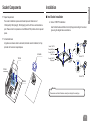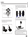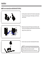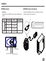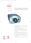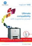
1
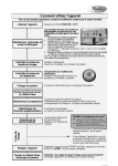
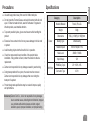
Specifications Use and keep product away from reach of children and pets. Category o not ingest the Thermal Grease, and avoid its contact with skin and D eyes. If contact is made with skin, wash off with water. If ingested or irritation persists, seek medical attention. Heatsink Material o prevent possible injuries, gloves must be worn while handling this T product. xcessive force exerted on the fan may cause damage to the fan and/ E or system. Cooler Avoid inserting objects into the fan while it is in operation. heck the components list and condition of the product before C installation. If any problem is found, contact the retailer to obtain a replacement. Zalman is not responsible for any damages caused by overclocking. uring transportation of the system, the cooler must be removed. D Zalman is not responsible for any damages that occur during the transport of a system. PWM Mate English Precautions Description Pure Al, Pure Cu Weight 920g Dimensions 135(L) X 100(W) X 160(H)mm Bearing Type 2 Ball-bearing Rotation Speed 1000~2150rpm ± 10% Noise Level 20dBA ~ 39dBA Input Voltage 12V PWM Duty Cycle 25 ~ 100% ± 5% Connector Type 4-Pin roduct design and specifications may be revised to improve quality P and performance. Disclaimer) Zalman Tech Co., Ltd. is not responsible for any damages due to external causes, including but not limited to, improper use, problems with electrical power, accident, neglect, alteration, repair, improper installation, or improper testing. 1 Components Common Components Cooler(CNPS10X) & PWM Mate Double-sided Tape Thermal Grease Extension Cable Washers Intel Socket 1156/775 Components Socket 1156/775 Clip Socket 1156/775 Clip Support Socket 775 Backplate Socket 1156/775 Bolt Guides Intel Socket1366 Components Socket 1366 Clip 2 Socket 1156 Nuts Socket 1156/775 Bolts (Silver) AMD Components Socket AM3/AM2+/AM2/754/939/940 Socket 1366 Clip Support Socket 1366 Bolts(Gold) AMD Clip Installation Space Requirements ¢ Intel Socket Installation The cooler’s installation requires unobstructed space with dimensions of 140mm(width),140mm(length), 165mm(height), and the CPU as a central reference point. Please check if components such as ODDs and PSU protrude into the required space. English Socket Components A. Socket 1156/775 Installation Insert the Bolt Guides and Bolts into the Clip Support according to the sockettype using the diagram below as reference. Air Guide Removal Air guides on enclosures must be removed, before the cooler’s installation, for they protrude into the cooler’s required space. Air Guide 140mm Socket 1156/775 Fixing Bolt(Silver) Socket 1156/775 Bolt Guide Socket 1156/775 Clip Support Socket 775 165mm Socket 1156 140mm Warning Please make sure the Bot Guides are correctly according to the socket-type. 3 Installation A-1. Socket 775 Installation A-2. Socket 1156 Installation Install the Socket 1156/775 Clip Support with the Socket 775 Backplate. M/B Install the Socket 1156/775 Clip Support with the Socket 1156 Nuts & Washers. Washer Socket 1156 Nut Socket 775 Backplate 4 M/B English Installation 3. Insert the Intel Socket 1156/775 or Socket 1366 Clip through the cooler’s heatpipes at an odd angle then center its orientation. Making sure that the cooler and the clip are centered, fasten the clip by tightening the Intel Socket Clip Fixing Bolts. B. Socket 1366 Installation 소켓1366 Socket 1366 Clip 클립지지대 Support 소켓1366 클립지지대 니플 Socket 1366 Washer 볼트 Socket 1366 Clip Support Fixing Bolt 니플 볼트 /B 보드 M 마더 보드 마더 소켓1156/775클립 Socket 1156/775 Clip또는 and 소켓1366클립 Socket 1366 Clip 2. C lear off any particles or residue from the CPU’s surface then spread (outwards from center) a thin but thorough layer of Thermal Grease on the CPU and the base of the cooler. 4. Connect the cooler’s 4-pin connector to the motherboard’s CPU Fan header. Warining 소켓1156/775클립 또는 소켓1366클립 The PWM fan’s operation will vary depending on the motherboard’s BIOS settings. After installation, the PWM Control Mode must be activated in the BIOS. For details regarding PWM Control Mode, please refer to the motherboard’s manual. 5 Installation ¢ AMD Socket Installation(Socket AM3/AM2+/AM2/754/939/940) 1. C lear off any particles or residue from the CPU’s surface then spread (outwards from center) a thin but thorough layer of Thermal Grease on the CPU and the base of the cooler. 2. P lace the cooler on the center of th CPU. Align and connect the Clip’s Lug Slot with the Lug of the motherboard’s retention frame. Press onto the Clip Lever when aligning the Lever’s Lug Slot with the Lug. Lug Slot Clip Lever Lug 3. Connect the cooler’s 4-pin connector to the motherboard’s CPU Fan header. Warining The PWM fan’s operation will vary depending on the motherboard’s BIOS settings. After installation, the PWM Control Mode must be activated in the BIOS. For details regarding PWM Control Mode, please refer to the motherboard’s manual. Installation ¢ PWM Mate Operation ¢ PWM Mate Extension Cable Operation 모드 버튼 [Mode Setting] Each iterative press of the PWM Mate’s button will select the next PWM Mate mode (4 modes). Mode AUTO Color Indicator RPM HI Red 1000~2150RPM MED Purple 1000~1950RPM LO Blue 1000~1500RPM Green 1000~2150RPM MANUAL Mode 모드Button 버튼 Auto Mode Indication LED 자동 모드 LED Manual RPM Dial N 수동 조절기 After removing the PWM Mate from the main unit, the PWM Mate can be relocated 수동 모드 LED 자동 모드 LED externally by connecting using the extension cable. White Caution When connecting the extension cable to the cooler’s port, please be sure to orient the cable’s white wire as shown in the diagram. Y RPM Dial 수동Manual 조절기 Manual ModeLED Indication LED 수동 모드 7