1
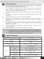
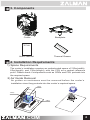
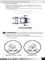
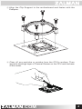
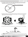
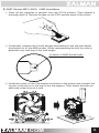
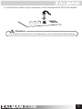
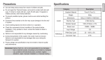
User’s Manual
CNPS 5X
Intel Socket 1155 / 1156 / 775 CPU
Core i7
Core i5
Core i3
Core 2 Extreme
Core 2 Quad
Core 2 Duo
Dual Core Pentium
Pentium D
Pentium 4
Celeron D
AMD Socket AM3 / AM2+ / AM2 CPU
Phenom II
Phenom
Athlon II
Athlon X2
Athlon FX
Athlon
Opteron
Dual-Core Opteron
Sempron
To ensure safe and easy installation,
please read the following precautions
www.ZALMAN.com
V 1.1
1. Precautions
1)
Avoid inserting objects or hands into the fan while it is in operation
to prevent product damage and injuries.
2)
Do not ingest the Thermal Grease, and avoid its contact with skin and
eyes. If contact is made with skin, wash off with water. If ingested or
irritation persists, seek medical attention.
3)
To prevent possible injuries, gloves must be worn while handling this
product.
4)
Excessive force exerted on the fan may cause damage to the fan and/
or system.
5)
Use and keep product away from reach of children.
6)
Check the components list and condition of the product before
installation. If any problem is found, contact the retailer to obtain a
replacement.
7)
During transportation of the system, the cooler must be removed.
Zalman is not responsible for any damages that occur during the
transport of a system.
8)
Product design and specifications may be revised to improve quality
and performance.
10)
Enable PWM function in BIOS settings after installation.
Disclaimer) Zalman Tech Co., Ltd. is not responsible for any damages due
to external causes, including but not limited to, improper use,
problems with electrical power, accident, neglect, alteration,
repair, improper installation, or improper testing.
2. Specifications
Model
Spec.
Fan
CNPS 5X
Material
Pure Copper and Aluminum
Weight
320g
Dimensions
127(L) Ⅹ 64(W) Ⅹ 134(H)㎜
Bearing-Type
Enter Bearing
RPM
1,400 ~ 2,800rpm ± 10%
Noise Level
20 ~ 32dBA ± 15%
Input Voltage
12V
Function
PWM Control, Auto Restart
.COM
1
3. Components
Cooler
Backplate
Th
er
User’s Manual
m
al
G
re
as
e
Thermal Grease
4. Installation Requirements
1) Space Requirements
The cooler’s installation requires an unobstructed space of 130㎜(width),
65㎜(length), and 135㎜(height), with the CPU as a central reference
point. Please check if components such as ODDs and PSU protrude into
the required space.
2) Air Guide Removal
Air guides on enclosures must be removed before the cooler’s
installation since they protrude into the cooler’s required space.
65㎜
135㎜
130㎜
.COM
2
3) Cooler Orientation
As shown in the diagram below, it is recommended that the cooler be
installed so that air flows from the cooler toward the enclosure’s rear
exhaust fan to be released.
※ Recommended cooler orientation may differ according to the
motherboard model.
5. Installation
1) Intel Socket 1155 / 1156 / 775 Installation
① Install the Clip Support to the motherboard according to the sockettype. (See diagram)
Socket 1155 / 1156
.COM
Socket 775
3
② Align the Clip Support to the motherboard and fasten with the
Pushpins.
M/B
③ Clear off any particles or residue from the CPU’s surface. Then
spread a thorough layer of Thermal Grease on the CPU and the base
of the cooler.
.COM
4
④ Completely unfasten the 2 bolts already assembled on the clip and adjust
the position to fit the Intel socket. When reassembling the bolt, be sure to
assemble only half way of the total length.
Location of Intel Socket bolts
⑤ Install the cooler on the Clip support as shown in the picture and connect the
lug slot of the clip on to the lug on the clip support. Then fasten the bolts on
each side a few turns at a time.
⑥ Connect the cooler’s 4-pin connector to the motherboard’s CPU Fan header.
M/B
Caution
The PWM fan’s operation will vary depending on the motherboard’s BIOS settings.
.COM
5
2) AMD Socket AM3 / AM2+ / AM2 Installation
① Clear off any particles or residue from the CPU’s surface. Then spread a
thorough layer of Thermal Grease on the CPU and the base of the cooler.
② Completely unfasten the 2 bolts already assembled on the clip and adjust
the position to fit the AMD socket. When reassembling the bolt, be sure to
assemble only half way of the total length.
Location of AMD Socket bolts
③ Install the cooler on the Clip support as shown in the picture and connect the
lug slot of the clip on to the lug on the clip support. Then fasten the bolts on
each side a few turns at a time.
.COM
6
④ Connect the cooler’s 4-pin connector to the motherboard’s CPU Fan header.
M/B
Caution
The PWM fan’s operation will vary depending on the motherboard’s BIOS settings.
.COM
7