1
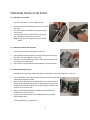
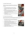
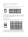
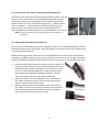
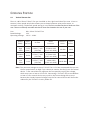
ISK 300-65
USER’S MANUAL
TABLE OF CONTENTS
INTRODUCTION
1.1
Case Specifications.…..…………………………………………………………………………………..3
1.2
Diagram…………………………………………………………………….…………………………………. 3
1.3
Power Supply Specifications…………………………………………………………………………. 4
HARDWARE INSTALLATION GUIDE
2.1
Removing the Top Panel.……………………………………………………………………………….5
2.2
Removing the Drive Tray Assembly……….……………………………………………………… 5
2.3
Motherboard Installation..……………………………………………………………………………. 5
2.4
Internal 2.5” Device Installation……………………………………………………………………. 5
2.5
External Slim 5.25” Device Installation…………………………………………………………. 6
CONNECTING THE FRONT I/O PORTS
3.1
USB 2.0 Ports………………………………………………….……………………………………………. 7
3.2
eSATA Port…………………………………….……………………………………………………………… 7
3.3
AC’97 / HD Audio Ports……………………….…………………………………………………………7
3.4
Switch and LED Connectors……………………………………………………………………………8
3.5
Rewiring Motherboard Header Connections………………………………………………… 8
COOLING SYSTEM
4.1
TriCool™ Exhaust Fan……………………………………………………………………………………. 9
1
ISK 300-65 USER’S MANUAL
At Antec, we continually refine and improve our products to ensure the highest quality. It’s
possible that your new case will differ slightly from the descriptions in this manual. This
isn’t a problem; it’s simply an improvement. As of the date of publication, all features,
descriptions, and illustrations in this manual are correct.
Disclaimer
This manual is intended only as a guide for Antec’s computer enclosures. For more
comprehensive instructions on installing the motherboard and peripherals, please refer to
the user’s manuals that come with those components.
Although care has been taken to prevent sharp edges in your Antec case, we strongly
recommend taking the appropriate time and care when working with it. Avoid hurried or
careless motions. Please use reasonable precaution.
This manual is not designed to cover CPU, RAM, or expansion card installation. Please
consult the motherboard manual for specific mounting instructions and troubleshooting.
Before proceeding, check the manual for your CPU cooler to find out if there are steps you must
take before installing the motherboard. While installing hardware, keep your case on a flat,
stable surface.
2
1.1
CASE SPECIFICATIONS
Case Type
Mini-ITX Desktop
Color
Black
Dimensions
96mm (H) X 222mm (W) X 328mm (D)
3.8” (H) x 8.7” (W) x 12.9” (D)
Net Weight
5.5 lbs / 2.5 kg
Cooling
Drive Bays
1 x Side 80mm TriCool™ fan
3 Drive Bays:
- 1 x External 5.25” slim drive bay
- 2 x Internal 2.5” drive bays
Expansion Slots
1 x Half-height slot
Motherboard Size
Mini-ITX
2 x USB 2.0
1 x eSATA
AC’97 / HD Audio In and Out
EP-65 power adapter and PCB
Front I/O Panel
Power Adapter
1.2
DIAGRAM
1.
2.
3.
4.
5.
6.
7.
Side 80mm TriCool™ fan
External slim optical 5.25” drive bay
Internal 2 x 2.5” HDD bays
Half-height expansion slot
Motherboard mount – Mini-ITX
Front I/O panel
EP-65 power adapter (not pictured)
3
1.3
POWER SUPPLY SPECIFICATIONS
The ISK 300-65 is powered by an EP-65 power adapter.
Input characteristics:
Rated Voltage
100 VAC ~ 240 VAC
Input Voltage Range
90 VAC ~ 264 VAC
Frequency Range
50 Hz ~ 60 Hz
Output characteristics:
Rated
Power
65W
Rated
Voltage
19V
Output
Current
0A ~ 3.42A
Voltage Range
18.4V ~ 20.0V
Ripple & Noise
< 350mV
A variety of industrial-grade safety circuitry will help protect your computer: OVP (Over Voltage
Protection), SCP (Short Circuit Protection), OTP (Over Temperature Protection), and OCP (Over
Current Protection). Sometimes the PSU will “latch” into a protected shutdown state. This
means that you will need to power off the adapter and clear the fault before it will function
again.
There are no user-replaceable fuses in the EP-65.
4
HARDWARE INSTALLATION GUIDE
2.1 REMOVING THE TOP PANEL
Place the case flat on an even, stable surface.
1.
2.
3.
Remove the three thumbscrews from the rear of the
top panel.
Grip the top panel and slide it back several inches
until it stops.
Grip the panel from the sides and lift it up until it
pulls completely free of the main chassis.
Note: Do not use your fingernails to pry or lift the
panels.
2.2 REMOVING THE DRIVE TRAY ASSEMBLY
Remove the top panel as detailed in section 2.1.
1.
2.
3.
Using a Phillips-head screwdriver, remove the three screws on the
top of the tray that attach it to the chassis.
Grip the tray in the middle and pull it a few inches toward the rear
of the case until it pulls loose.
Pull the drive tray assembly up and completely free of the chassis.
2.3 MOTHERBOARD INSTALLATION
Remove the top panel and remove the drive tray assembly as detailed in sections 2.1 and 2.2.
1.
2.
3.
4.
Lay the case down, with the open side facing up. The drive cages and
power supply should be visible.
Make sure you have the correct I/O panel for your motherboard. If
the panel provided with the case isn’t suitable, please contact your
motherboard manufacturer for the correct I/O panel. Install the I/O
panel at the rear of the case.
Align your motherboard with the motherboard standoff holes
located at the rear of the case.
Screw in your motherboard to the standoffs with the provided
Phillips-head screws.
Your motherboard is now installed.
5
2.4 INTERNAL 2.5” DEVICE INSTALLATION
Remove the top panel as described in section 2.1. Included at the top
of the drive tray assembly is a HDD tray that can support up to two
2.5” devices.
1.
2.
3.
4.
5.
6.
On the right side of the drive tray assembly, remove the
thumbscrew holding the HDD tray to the rest of the device.
Slide the HDD tray back a centimeter so the locking hinges
unhook.
Pull the HDD tray away from the drive tray assembly.
Align your 2.5” device with the HDD tray. Invert the tray so the
lower screw holes are accessible, then secure the device to the
tray with the provided Phillips-head screws.
Reattach the HDD tray to the drive tray assembly and replace
the thumbscrew.
Connect the data and power connectors from the motherboard
and power adapter to the device.
2.5 EXTERNAL SLIM 5.25” DEVICE INSTALLATION
Remove the top panel and drive tray assembly as described in sections 2.1 and 2.2. There is one
externally accessible 5.25” drive bay that is compatible with a slim 5.25” optical drive.
1.
2.
3.
4.
5.
While facing the front of the case, press on the upper right of
the front of the 5.25” drive bay cover until it clicks, then release
to allow the cover to unhinge.
Remove the drive bay face plate by applying pressure to the
inside of the plate until it pops free of the bezel.
Install your slim optical drive in the drive bay assembly by
sliding it into position from the rear of the assembly. Secure the
device in place by attaching the included small screw on the
right-hand side of the tray.
Connect the data and power connectors from the motherboard
and power adapter to the device.
Replace the drive tray assembly in the chassis.
6
CONNECTING THE FRONT I/O PORTS
3.1 USB 2.0
Connect the front I/O panel USB cable to the USB header pin on your motherboard. Check
the motherboard manual to ensure that it matches the table below:
1
2
Pin
9 10
Signal Names
Pin
Signal Names
1
USB Power 1
2
USB Power 2
3
Negative Signal 1
4
Negative Signal 2
5
Positive Signal 1
6
Positive Signal 2
7
Ground 1
8
Ground 2
9
Key (No Connection)
10
Empty Pin
3.2 ESATA
You will find a SATA connector on a cable attached to the front ports. This internal SATA
connector is designed to connect to a standard SATA connector on your motherboard. This
will allow high-speed external hard disk enclosures such as the Antec MX-1 to run at the
same speeds as internally installed hard disks.
3.3 AC’97 / HD AUDIO PORTS
There is an Intel® standard 10-pin AC’97 connector and an Intel® 10-pin HDA (High
Definition Audio) connector linked to the front panel of the case.
10 6 4 2
9 753 1
Pin
Signal Names
(HDA)
Pin
Signal Names
(AC’97)
1
MIC2 L
1
MIC In
2
AGND
2
GND
3
MIC2 R
3
MIC Power
4
AVCC
4
NC
5
FRO-R
5
Line Out (R)
6
MIC2_JD
6
Line Out (R)
7
F_IO_SEN
7
NC
8
Key (no pin)
8
Key (no pin)
9
FRO-L
9
Line Out (L)
10
LINE2_JD
10
Line Out (L)
You can connect either the AC’97 or the HDA connector, depending on your motherboard.
Locate the internal audio connectors from your motherboard or sound card and connect
the corresponding audio cable. Consult your motherboard or sound card manual for the
pin-out positions. Even if your system supports both standards, only use one connector.
7
3.4 POWER SWITCH / RESET SWITCH / HARD DISK DRIVE LED CONNECTORS
Connected to your front panel are LED and switch leads for power, reset, and
HDD LED activity. Attach these to the corresponding connectors on your
motherboard. Consult your motherboard user’s manual for specific pin
header locations. For LEDs, colored wires are positive ( + ). White or black
wires are negative ( – ). If the LED does not light up when the system is
powered on, try reversing the connection. For more information on
connecting LEDs to your motherboard, see your motherboard user’s manual.
Note: Polarity (positive and negative) does not matter for
switches.
3.5 REWIRING MOTHERBOARD HEADER CONNECTIONS
There may come a time when you need to reconfigure the pin-out of a motherboard header connector.
Examples could be for your USB header, audio input header, or some other front panel connector such
as the Power Button connector.
Before performing any work, please refer to your motherboard user’s manual or your motherboard
manufacturer's website to be sure of the pin-out needed for your connector. We strongly recommend
making a notated drawing before beginning work so that you can recover if your work gets disturbed.
1.
2.
3.
Determine which wires you need to remove in order to rewire your
plug to match the USB pin-outs on your motherboard (refer to your
motherboard user’s manual). Working on one connector at a time,
use a very small flathead screwdriver or similar tool to lift up on
the black tab located beside the gold posts (squares). This will
allow you to easily slide out the pins from the USB plug.
Working carefully so as not to damage the wires, connectors, or
pins, slowly remove the pin from the connector. Repeat these
steps for each wire you need to change.
Working carefully so as not to damage the wires, connectors or
pins, slowly reinsert the pin into the correct slot of the connector
then snap closed the black tab that was lifted in step 1. Repeat
these steps for each wire you need to change.
8
COOLING SYSTEM
4.1
TRICOOL™ EXHAUST FAN
There is a 80 x 25mm TriCool™ fan pre-installed on the right-hand side of the case. It has an
external, three-speed switch that allows you to choose between quiet performance, or
maximum cooling. The default speed setting is Low. The fan is mounted so that air blows out of the
case. There are externally accessible switches for these fans located at the rear of your case.
Size:
Rated Voltage:
Operating Voltage:
80 x 25mm TriCool™ fan
12V
10.2V - 13.8V
Speed
(RPM)
Input
Current
Airflow
Static
Pressure
Acoustic
Noise
Input
Power
High
2600
0.2A
(Max.)
0.96 m³ / min
(34 CFM)
3.04mm-H2O
(0.12 inch-H2O)
30 dBA
2.4W
Medium
2000
0.15A
0.74 m³ / min
(26 CFM)
1.79mm-H2O
(0.07 inch-H2O)
24.3 dBA
1.8W
Low
1500
0.1A
0.55 m³ / min
(20 CFM)
1.0mm-H2O
(0.03 inch-H2O)
18.05 dBA
1.2W
Note: The minimum voltage to start a TriCool™ fan is 5V. We recommend that you set
the fan speed switch to High if you choose to connect the fan(s) to a fan control
device. A fan control device regulates the fan speed by varying the voltage,
which may start as low as 4.5V to 5V. Connecting a TriCool™ fan set on Medium
or Low to a fan-control device may result in the fan not being able to start
because the already lowered voltage from the fan control device will be further
reduced by the TriCool™ circuitry below 5V.
9
Antec, Inc.
47900 Fremont Blvd.
Fremont, CA 94538
USA
tel: 510-770-1200
fax: 510-770-1288
Antec Europe B.V.
Stuttgartstraat 12
3047 AS Rotterdam
Netherlands
tel: +31 (0) 10 462-2060
fax: +31 (0) 10 437-1752
Customer Support: US & Canada
1-800-22ANTEC
[email protected]
Europe
+31 (0) 10 462-2060
[email protected]
www.antec.com
© Copyright 2009 Antec, Inc. All rights reserved.
All trademarks are the property of their respective owners. Reproduction in whole or in part
without written permission is prohibited.
10