1
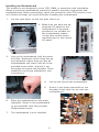
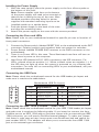
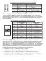
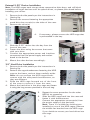
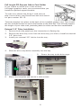
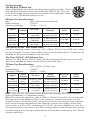
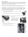
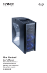
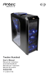
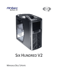
Nine Hundred User’s Manual Manuel de l’utilisateur Anwenderhandbuch Manuale per l’operatore Manual del usuario পᡅ䂀ᯢ At Antec, we continually refine and improve our products to ensure the highest quality. As such, your new case may differ slightly from the description in this manual. This isn’t a problem; it’s simply an improvement. As of the date of publication, all features, descriptions, and illustrations in this manual are correct. Disclaimer This manual is intended only as a guide for Antec’s Computer Enclosures. For more comprehensive instructions on installing the motherboard and peripherals, please refer to the user’s manuals that come with those components. Nine Hundred User’s Manual Nine Hundred – Gaming Case The Nine Hundred comes without a power supply. Make sure you choose a power supply that is compatible with your computer components and has a long enough power harness to reach your motherboard and peripheral devices. We recommend our TruePower Quattro, TruePower Trio, or NeoPower power supplies for the latest ATX specification compliance, broad compatibility, and power savings capability. Although care has been taken to prevent sharp edges in your Antec case, we strongly recommend taking the appropriate time and care when working with it. Avoid hurried or careless motions. Please use reasonable precaution. Attention: The Nine Hundred comes with a top storage area. Antec does not recommend that users put any liquid-containing items (drinks, ice cream, candles, perfume dispensers, etc.) in this area. It was designed to hold your personal media player, digital camera, keys, coins, etc. Setting Up 1. 2. 3. Place the case upright on a flat, stable surface so that the rear panel (power supply and expansion slots) is facing you. Remove the panel thumbscrews from a side panel and open it by sliding it towards yourself. Note: Place the panel thumbscrews carefully aside as they are NOT interchangeable with the HDD cage thumbscrews. Remove the panel thumbscrews from the other side panel and open it by sliding it towards you. Place the screws carefully aside. Inside the case is the power supply mount at the lower rear of the case and the 5.25” drive bay area with two HDD cages inside the bays. You will also find some wiring with marked connectors (USB, PWR etc.), an installed I/O panel and a toolbox containing more hardware (screws, brass standoffs, etc.) Note: Don’t use your fingernail to pry or lift the panels. 1 Installing the Motherboard This manual is not designed to cover CPU, RAM, or expansion card installation. Please consult the motherboard manual for specific mounting instructions and troubleshooting. Before proceeding, check the manual for your CPU cooler to find out if there are steps you must do before installing the motherboard. 1. Lay the case down so that the open side is up. 2. Make sure you have the appropriate I/O panel for the motherboard. If the panel provided is not suitable for the motherboard, please contact the mother board manufacturer for the correct I/O panel. 3. Line up the motherboard with the standoff holes. Determine which holes line up and remember where they are. Not all motherboards will match with all of the provided screw holes, and this is not necessary for proper functionality. Some standoffs may be pre-installed for your convenience. 4. Lift up and remove the motherboard. 5. Screw in the brass standoffs to the threaded holes that line up with the motherboard. 6. Place the motherboard on the brass standoffs. Screw in the motherboard to the standoffs with the provided Phillips-head screws. 7. The motherboard is now installed. 2 Installing the Power Supply 1. 2. 3. With the case upright, place the power supply on the four silicone pads on the bottom of the case. Note: Power supplies with fans on the bottom of the power supply will need to be mounted so that the fan is facing the top of the case. Nine Hundred provides mounting holes for power supplies with standard mounting layouts to be installed upside up or upside down. Push the power supply to the back of the case and align the mounting holes. Attach the power supply to the case with the screws provided. Connecting the Ports and LEDs Note: Please refer to your motherboard manual for specific pin outs or location of front panel connectors. 1. 2. 3. 4. Connect the Reset switch (labeled RESET SW) to the motherboard at the RST connector. Polarity (positive and negative) does not matter for switches. Power Switch (labeled POWER SW) connects to the PWR connector on the motherboard. There is no Power LED in this case. Three illuminated case fans will turn on when there is power to the computer. Hard Drive LED (labeled H.D.D. LED) connects to the IDE connector. For LEDs, colored wires are positive (+). White or black wires are negative (–). If the LED does not light up when the system is powered on, try reversing the connection. For more info on connecting LEDs to your motherboard, see your motherboard manual. Connecting the USB Ports Note: Please check the motherboard manual for the USB header pin layout and make sure it matches the table below. Motherboard USB Pin Layout 1 2 9 10 Pin Signal Names Pin Signal Names 1 USB Power 1 2 USB Power 2 3 Negative Signal 1 4 Negative Signal 2 5 Positive Signal 1 6 Positive Signal 2 7 Ground 1 8 Ground 2 9 Key (No Connection) 10 Empty Pin Connecting the IEEE 1394 (FireWire®, i.Link®) Port Note: Please check the motherboard manual for your IEEE 1394 header pin layout and make sure it matches the following table. If you intend to connect the front FireWire port to an IEEE 1394 add-on card that comes with an external-type IEEE 1394 connector, you will need a FireWire Internal Adapter. To order one, please visit Antec’s web store at http://www.antec.com/StoreFront.bok and search for part number 30031. This adapter will allow you to connect the front IEEE 1394 port to the external-type connector. 3 Pin Assignment for Front Panel IEEE 1394 Connector 1 2 9 10 Pin Signal Names Pin Signal Names 1 TPA+ 2 TPA– 3 Ground 4 Ground 5 TPB+ 6 TPB– 7 +12V (Fused) 8 +12V (Fused) 9 Key (No Pin) 10 Ground Connecting the Audio Ports (AC’97 and HDA) There is an Intel® standard 10-pin AC’97 connector and an Intel® 10-pin HDA (High Definition Audio) connector. You can connect either the AC’97 or the HDA connector, but not both at once, to your motherboard depending on the spec of the motherboard. Pin Assignment for Audio Ports (HDA and AC’97) 10 6 4 2 97531 Pin Signal Names (HDA) Pin Signal Names (AC’97) 1 MIC2 L 1 MIC In 2 AGND 2 GND 3 MIC2 R 3 MIC Power 4 AVCC 4 NC 5 FRO-R 5 Line Out (R) 6 MIC2_JD 6 Line Out (R) 7 F_IO_SEN 7 NC 8 Key (no pin) 8 Key (no pin) 9 FRO-L 9 Line Out (L) 10 LINE2_JD 10 Line Out (L) Flexi Drive Bay System The Nine Hundred comes with nine 5.25” external drive bays at the front of the case. There are two HDD cages preinstalled inside the bottom six 5.25” bays. Each HDD cage occupies three consecutive 5.25” drive bays and can house three hard disk drives. For maximum flexibility you can mount the HDD cage anywhere within the external drive bays (i.e., you are not limited to the bottom six bays). Possible Drive Bay combinations include but are not limited to: • External 3 x 5.25” + internal 6 x HDD – default • External 9 x 5.25” by removing both HDD cages • External 6 x 5.25” + internal 3 x HDD – by removing one HDD cage • External 3 x 5.25” + internal 3 x HDD + VGA cooling duct – by adding the middle fan to one of the HDD cages (see Cooling System) 4 External 5.25” Device Installation Note: The HDD cages each occupy three consecutive drive bays, and will block installation of larger devices such as optical drives, so please plan ahead before installing your drives. 1. 2. 3. Remove both side panels per the instructions in Setting Up. Remove the screws fastening the appropriate metal drive bay cover(s) to the sides of the case. Remove the cover(s). 4. 5. 6. 7. 8. If necessary, please remove the HDD cage that is preinstalled in the bay. Slide the 5.25” device into the bay from the front of the case. Fasten the drive using the screws that came with your drive. Connect the appropriate power and interface connectors from the power supply and motherboard to the device. Mount the other devices accordingly. 3.5” Hard Drive Installation 1. 2. 3. 4. Remove both side panels per the instructions in Setting Up. Remove the cage thumbscrews fastening the HDD cage to the frame, and set them carefully aside. Note: do not confuse the HDD cage thumbscrews with the side panel thumbscrews, as they are different. Slide the HDD cage forward out of the front of the case to remove it from the case. Mount the hard drive in the drive cage and fasten it using the long screws provided in the tool bag. 5. 6. 7. Repeat the same procedure for the other HDD(s) as necessary. Slide the HDD cage back into the case and fasten it with thumbscrews. Connect the appropriate connector(s) from the power supply to the device(s). Note: There is a middle fan bracket preinstalled on one of the HDD cages. Remove the middle fan bracket from the HDD cage if you decide to mount your hard drives into this cage. 5 Full Length PCI-Express Add-in Card Holder If you intend to install one of the newest full-length graphics cards, we recommend that you install the optional support bracket. To order one, please visit Antec’s web store at http://www.antec.com/StoreFront.bok and search for part number 30115. Twist the bracket into place at the back of the installed graphic card. Then install the two included screws to secure the bracket to the drive bay. This will help support the weight of your video card, protecting both the video card and the motherboard. External 3.5” Drive Installation 1. 2. 3. Remove both side panels per the instructions in Setting Up. Remove the drive bay cover from the drive bay you wish to install an external 3.5” drive into. Install your external 3.5” device into the tray. 4. Slide the drive tray/device assembly into the bay. 5. 6. Screw the tray to the drive cage. Mount the faceplate and secure it with screws. 6 Cooling System The Big Boy 200mm fan: Antec understands your desire for the coolest gaming system. That’s why the Nine Hundred comes with a Big Boy 200mm fan. This fan has a three-speed switch that lets you choose the speed best suited to your need. The default setting is Low. 200mm Fan Specifications: Size: Rated Voltage: Operating Voltage: 200 x 30mm three-speed fan 12V DC 10.8V ~ 13.2 V Speed Input Current Air Flow Static Pressure Acoustical Noise Input Power High 800 RPM 0.3A 3.799 m³ / min (134 CFM) 0.688 mm-H2O (0.027 inch-H2O) 29.4 dBA 3.6 W Medium 600 RPM 0.17A 3.07 m³ / min (108 CFM) 0.397 mm-H2O (0.016 inch-H2O) 26.5 dBA 2.04 W Low 400 RPM 0.08A 2.34 m³ / min (82 CFM) 0.197mm-H2O (0.008 inch-H2O) 23.6 dBA 0.96 W The Front TriCool™ LED Intake Fans: The Nine Hundred comes with two 120 x 25mm TriCool™ blue LED fans which are pre-installed in front of each HDD cage to cool the hard drives. These fans are installed so the air will be blown into the case. The Rear TriCool™ LED Exhaust Fan There is a 120 x 25mm TriCool™ blue LED fan preinstalled at the rear of the case. The fan is installed so the air will be blown out of the case. 120mm Fan Specifications: Size: Rated Voltage: Operating Voltage: 120 x 25mm TriCool™ Fan 12V DC 10.2V ~ 13.8V Speed Input Current Air Flow Static Pressure Acoustical Noise Input Power High 2000 RPM 0.24A (Max.) 2.24 m³ / min (79 CFM) 2.54 mm-H2O (0.10 inch-H2O) 30 dBA 2.9 W Medium 1600 RPM 0.2A 1.59 m³ / min (56 CFM) 1.53 mm-H2O (0.06 inch-H2O) 28 dBA 2.4 W Low 1200 RPM 0.13A 1.1 m³ / min (39 CFM) 0.92 mm-H2O (0.04 inch-H2O) 25 dBA 1.6 W Note: These TriCool™ fans have a three-speed switch that lets you choose between quiet, performance, or maximum cooling. Note: The minimum voltage to start a 120mm TriCool™ fan is 5V. We recommend that you set the fan speed to High if you choose to connect the fan(s) to a fan control device or to the Fan-Only connector found on some Antec power supplies. A fan control device regulates the fan speed by varying the voltage, which may start as low as 4.5V to 5V. Connecting a TriCool™ fan set on Medium or Low to a fan-control device may result in the fan not being able to start because the already lowered voltage from the fan control device will be further reduced by the TriCool™ circuitry below 5V. 7 The Optional Fans There are two optional 120mm fan mounts—the side fan (on the left side panel) and the middle fan (at the rear end of the HDD cage). We recommend using Antec 120mm TriCool™ fans and setting the speed to Low. These two fans should be installed so that the air is blowing into the case. The Side Fan — the side fan opening is there to enhance VGA cooling. Just drop a fan into the bracket on the side panel so that air is blowing into the case. The Middle Fan — the middle fan is designed to cool the CPU, VGA card or the power supply if you choose to use a fanless power supply depending on which drive bays you install the HDD cage into. You can use the middle fan on whichever drive cage you do NOT install hard drives in. This design is especially useful in cooling dual VGA card implementations. 1. To remove the black middle fan mount, press in on the clips that secure the bay to its cage. 2. Place a 120mm fan inside the mount and press it into place. 3. Use the long screws provided to secure the fan to the mount. 4. Run the power (and control switch if using a TriCool™ fan) through the cable guide that runs along the side of the fan mount. 5. Clip the fan mount/fan assembly onto the back of an empty HDD cage. 6. Connect the fan to the power supply. 8 Antec, Inc. 47900 Fremont Blvd. Fremont, CA 94538 USA tel: 510-770-1200 fax: 510-770-1288 Antec Europe B.V. Stuttgartstraat 12 3047 AS Rotterdam The Netherlands tel: +31 (0) 10 462-2060 fax: +31 (0) 10 437-1752 Customer Support: US & Canada 1-800-22ANTEC [email protected] Europe +31 (0) 10 462-2060 [email protected] www.antec.com © Copyright 2007 Antec, Inc. All rights reserved. All trademarks are the property of their respective owners. Reproduction in whole or in part without written permission is prohibited. Printed in China.