1
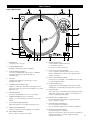
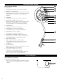
Direct Drive Professional
Stereo Turntable
AT-PL120
Installation and Operation
Direct Drive Professional Stereo Turntable
Installation and Operation
Warning: To prevent fire or shock hazard, do
not expose this appliance to rain or moisture.
Attention: Pour prévenir feu ou choc
électrique, ne pas exposé l’appareil à la pluie
ou à l’humidité.
Cuidado: Para evitar descargas eléctricas o el
peligro de incendio, no exponga este aparato a la lluvia o humedad.
Introduction
Thank you for purchasing the AT-PL120. Audio-Technica has
been a leading manufacturer of innovative stereo phonograph
products for more than 40 years. We are pleased to provide this
turntable, with its excellent performance and many convenient
features, for your enjoyment.
The AT-PL120 stereo turntable system features the following:
• Direct drive high-torque motor
CAUTION
RISK OF ELECTRIC SHOCK
DO NOT OPEN
AVIS
RISQUE DE CHOC ÉLECTRIQUE
NE PAS OUVRIR
PRECAUCION: RIESGO DE DESCARGAS ELECTRICAS
NO SE ABRA
To prevent electric shock, do not remove the
cover. There are no user-serviceable parts
inside. Internal adjustments are for qualified
professionals only. Refer all servicing to
qualified service personnel.
Pour prévenir un choc électrique, ne pas ouvrir
le couvercle. Il n’y aucune pièces de rechanges
à l’intérieur. Tout ajustement interne doit être
fait par une personne qualifié seulement.
Référez tout réparation au personnel qualifié.
Para reducir el riesgo de descargas eléctricas,
no se abra la cubierta. No existen partes de
reemplazo para que el usuario pueda reparar por dentro el aparato. Deje cualquier clase de mantenimiento en manos de técnicos
especializados.
• Selectable 33/45/78 rpm speeds
• Selectable internal stereo phono pre-amplifier
• S-shaped tone arm assembly with:
• Adjustable counterweight
• Anti-skate adjustment
• Tone arm height adjustment and lock
• Tone arm lift with hydraulic action and lift lever
• Tone arm rest with locking mechanism
• Selectable high-accuracy quartz-controlled pitch lock
• Selectable +/–10% or +/– 20% pitch adjustment ranges
• Stroboscopic platter speed indicator
• Forward and reverse play
• Cast aluminum record platter with slip mat
• Start/stop button with remote start/stop input
• Pop-up stylus target light
• 45-rpm adapter with storage receptacle
• Receptacle for extra headshell
Caution: To prevent electric shock, do not
use the polarized plug with an extension cord,
receptacle, or other type of electrical outlet
unless the wide blade can be easily inserted
into a matching slot.
Attention: Pour éviter toute décharge
électrique, ne pas utiliser la prise polarisée avec un cordon de
prolongation, réceptacle ou tout autre dispositif électrique, à
moins que la broche large puisse s’insérer facilement dans un
trou de même taille.
Precaución: Para evitar descargas eléctricas, no use clavijas
polarizadas con una extension de cable, receptáculo, u otro tipo
de toma eléctrica a menos que el conductor plano más ancho
de la clavija pueda insertarse facilmente en el ranura del enchufe
que le corresponde.
2
• Adjustable feet for leveling
• Removable hinged dust cover
To assure maximum satisfaction from this product, please read
the information and follow the instructions presented in this
manual. Please keep the manual in an accessible location for
future reference.
We suggest that you save all the packaging materials for
possible future storage, moving, or shipping.
Caution: To avoid stylus damage, make certain the included
stylus guard is in place whenever the turntable is being
installed, moved, or cleaned.
Main Features
Figure 1 Main Features
8
8
18
9
7
PHONO OUT LINE OUT
10
11
17
115
12
13
1
2
3
4
5
6
1. Power Dial
Controls power to the unit.
2. Start/Stop Button
Engages and disengages the motor/platter.
3.
Platter Speed Buttons
Select 33 or 45 RPM platter speed. (Note: 78 RPM is
selected by pressing the 33 and 45 buttons
simultaneously.)
4. PLATTER
Cast aluminum platter mounts directly to center
spindle/motor shaft.
5. Strobe Dots (On platter edge)
Operate in conjunction with stroboscopic light located
under power dial (1) to provide visual indication of accurate
platter speeds.
16
15
14
11. DIRECTION BUTTON
Controls platter’s rotational direction:
F – Forward (clockwise)
R – Reverse (counter-clockwise)
12. PITCH ADJUST SLIDE CONTROL
Use in conjunction with pitch button (15) to vary the
platter’s rotational speed. In the center detent position
quartz lock is active.
13. PITCH SELECTION INDICATOR
Shows Green for standard or locked RPM setting, or Red
for a pitch-adjusted setting.
14. QUARTZ SPEED LOCK
Toggles between internal quartz-locked reference and
variable pitch controlled by pitch adjust slide control (12).
6. CENTER SPINDLE
Precision-machined platter mount on motor shaft.
15.
7. 45-RPM ADAPTER (Shown in receptacle)
Adapts 7” records with large center holes to fit center
spindle.
16. POPUP STYLUS TARGET LIGHT
Provides illumination directed at the stylus position for
easier cueing in poor light.
8. DUST COVER HINGE HOLDERS
Attachment points for removable hinged dust cover.
17. VOLTAGE SELECTOR SWITCH
(Access through holes in platter)
Selects operating voltage (115V or 230V AC, 50/60 Hz).
9. HEADSHELL RECEPTACLE
Storage receptacle for extra headshell (not included).
10. TONE ARM ASSEMBLY
Refer to Figure 2 on page 4 for details.
PITCH BUTTON
Selects the range of pitch variation permitted by the pitch
adjust slide control (12). (See page 7 for information on
locking or adjusting platter speed.)
18. PRE-AMP SELECTOR SWITCH
(Access through holes in platter)
Allows the internal stereo phono pre-amp to be bypassed
when the turntable is used with equipment having
magnetic phono inputs.
3
Tone Arm Assembly Diagram
Figure 2 Tone Arm Assembly
29
19. HEADSHELL
Standard, interchangeable stereo cartridge headshell.
28
20.
27
HEADSHELL LOCKING RING
Rotate counter-clockwise (to the left) to draw the inserted
headshell firmly into its seated, locked position. Rotate the
ring a full turn to the right to permit removal of the
headshell.
26
25
21. TONE ARM
S-shaped tone arm geometry reduces tracking error.
22.
24
TONE ARM ASSEMBLY HEIGHT ADJUST
Raises and lowers the entire tone arm assembly to allow
the tone arm to remain parallel to the record surface.
(The proper setting is “0” for the included cartridge.)
23
22
23. Tone Arm Lift
Elevates tone arm above record surface.
24. TONE ARM REST WITH LOCKING CLAMP
Locking clamp secures tone arm during transport.
25. TONE ARM LIFT ADJUST SCREW
Used to set the amount of tone arm lift.
21
26. TONE ARM LIFT CONTROL LEVER (“Cueing Lever”)
Controls action of tone arm lift. (Note: Lift mechanism is
hydraulically damped to slow tone arm descent.)
27.
ANTI-SKATE CONTROL
Applies a small inward force to the tone arm,
counteracting the tendency of the tone arm to move
outward due to forces created by the stylus in the
record groove.
20
19
28. COUNTERWEIGHT
Balances the tone arm and provides adjustment for proper
downward tracking force on the stylus.
29.
TONE ARM ASSEMBLY HEIGHT LOCK
(Hidden under counterweight in drawing)
Locks the tone arm height setting. (Always fully unlock
before attempting to make a height adjustment.)
Rear View Diagram
Figure 3 Rear View of Turntable
30. REMOTE START/STOP (1/ ” jack)
This 1/ ” jack (2 conductor Tip/Sleeve) provides a normally
open dry-contact closure that allows for remote start/stop
of platter.
4
4
PITCH
30
OUTPUT
4
REMOTE
START/STOP
Initial Setup
Unpacking
Carefully unpack the turntable and verify that the following
parts are included and intact:
• Slip mat (above the dust cover)
• Dust cover (above the turntable)
• Platter (under the turntable)
• Dust cover hinges (accessory section of the
foam packaging)
• 45 RPM adapter (accessory section)
• Counterweight (accessory section)
• Headshell with pre-mounted cartridge (accessory section)
• Power cord (accessory section)
WE RECOMMEND THAT YOU SAVE ALL PACKAGING
MATERIALS FOR POSSIBLE FUTURE STORAGE, MOVING OR
SHIPPING.
Assembling the Turntable
The AT-PL120 requires some assembly before first use.
IMPORTANT: Do not connect the AC power cord until
assembly is complete.
Setting the Voltage Selector Switch
This turntable has the capability to be used with either 115V or
230V AC power, 50/60 Hz. The voltage selector switch is
located on the top of the housing deck, under the platter. Set
the switch according to the voltage in your area. [See Figure 4.]
(Note: The turntable comes shipped with the voltage selector
switch set for 115V AC.)
Figure 4 Voltage Switch and Pre-amp Selector Switch
Pre-amp Selector
Switch
Voltage
switch
pre-amp selector switch to the PHONO OUT position and
connect the turntable’s output cables to the PHONO inputs on
your system, observing Red for Right channel and White for
Left channel.
If your system does not have a PHONO (magnetic phono) input,
set the pre-amp selector switch to LINE OUT and connect
the turntable’s output cables to the Auxiliary (AUX) or other
high-level inputs on your system, observing Red for Right
channel and White for Left channel.
When using the turntable with a computer sound card, set the
switch to LINE OUT and connect the turntable to the audio line
input on the computer sound card. Note: An audio adapter (not
included) may be required to interface the two RCA jacks of the
turntable output cable to the computer sound card input.
Assembling the Tone Arm
(Note: The headshell and cartridge are supplied pre-assembled
with the AT-PL120.)
1. Remove the vinyl tie used to secure the tone arm during
shipment. Temporarily secure the tone arm in the tone arm
rest with the locking clamp. [Figure 2, page 4, #24.]
2.
Attach the headshell assembly by inserting it into the
socket at the front of the tone arm [See Figure 5.] (It’s
good practice always to hold a headshell assembly by the
left and right edges of the headshell to reduce the
possibility of damaging the stylus or disrupting the
cartridge wiring.)
3.
While holding the headshell in position, rotate the
headshell locking ring counter‑clockwise (to the left).
As the ring turns, it pulls the headshell into its seated
position. (Rotate the ring a full turn to the right to permit
removal of the headshell.)
4.
With its black dial toward the front, use a screwing motion
to attach the counterweight to the arm extending back
from the tone arm pivot [Figure 2, page 4, #28]; the
counterweight will engage the spiral groove in the rear arm
section and move forward.
Figure 5 Headshell
Setting the Pre-amp Selector Switch
For increased flexibility of use, this turntable has an internal stereo phono pre-amplifier. The pre-amp selector switch
located in the rear-center of the housing deck under the platter
[See Figure 4], selects the internal stereo pre-amplifier (LINE
OUT), or bypasses the pre-amp (PHONO OUT) for use with
systems having specialized magnetic phono input jacks. The
audio output cable’s Red RCA-type plug is the Right channel;
the White plug is the Left channel.
If the system you are using has a PHONO input, set the
5
Initial Setup (continued)
Assembling the Turntable Platter and Slip Mat
1. Carefully place the turntable platter on the center spindle,
making certain the platter is fully seated on the spindle.
[See Figure 6.]
2. Place the soft black slip mat on top of the platter.
Figure 6 Platter and Slip Mat
Assembling the Dust Cover
1. Insert the T-shaped ends of the dust cover hinges into the
two hinge receptacles located at the back of the turntable
housing. When properly installed, the flat part of the cover
hinges should be facing away from the turntable housing
at about a 45° angle.
2.
Holding the dust cover over the turntable, carefully guide
the cover hinges into the two slots molded into the rear of
the dust cover. The springs in the hinges allow the cover
to be held open at about a 45° angle if desired. (Note:
There is only one “open” position; the hinges do NOT
permit the cover to stand “straight up.”)
3.
To remove the dust cover from the turntable, gently
disengage the hinges from the slots in the cover. This is
usually easier when the cover is in the “closed” position.
Slowly and carefully lift straight up until the cover is clear
of the unit. The hinges may then be removed from the
turntable base, if desired.
Setting Tone Arm Balance and Tracking Force
To allow the cartridge to properly track in a record, the tone
arm balance and tracking force must be carefully set to the
cartridge manufacturer’s specifications. Failure to properly set
up the tone arm assembly can cause damage to the cartridge
stylus and/or records.
(Note: Once the stylus protective cover has been removed and
the tone arm locking clamp has been released, take extreme
care not to damage the stylus. Do not allow it to drag or
scrape across the slip mat.)
Tone Arm Setup:
1. Set the anti-skate adjustment to “0”.
[Figure 2, page 4, #27.]
2. Remove the clear protective stylus cover, carefully sliding
it straight forward, off the front of the cartridge.
3. While gently holding the headshell to stabilize the tone
arm, release the tone arm locking clamp. At this point, the
tone arm is unbalanced and free to swing.
4.
6
While gently holding the headshell, carefully rotate the
counterweight until the tone arm is horizontally balanced
and hovers freely just above the platter without touching
the platter surface.
5. Lock the tone arm back into the tone arm rest.
6.
While holding the counterweight steady, and without any
rotation, carefully rotate only the black stylus force gauge
ring (which turns independently of the counterweight) until
the “0” on the gauge ring lines up with the centerline
marked along the top of the rear arm.
7.
Refer to the cartridge manufacturer’s specifications for
recommended tracking force. Rotate the entire counterweight counterclockwise without touching the black gauge
ring, moving the counterweight forward, until the desired
value on gauge ring lines up with the centerline marked on
the rear arm. Refer to the specifications section for
tracking force value for the cartridge that shipped with the
turntable.
Setting Anti-skate
A small inward “anti-skating” force can be applied to the tone
arm to compensate for outward forces resulting from cartridge/
tone arm interaction with the record. For best performance
during normal turntable use, set the anti-skate control knob
[Figure 2, page 4, #27] to the same setting as the tracking force
dial. Refer to the specifications section for tracking force value
of the cartridge that shipped with the turntable.
In case of substantial use of back-cueing, scratching or reversedirection operation, you may prefer to use less, or no, anti-skate
compensation.
Setting Tone Arm Assembly Height
The tone arm assembly height adjustment allows for the tone
arm to be positioned parallel to the record surface, when using
extra-tall cartridge bodies, thick slip mats or thick records (i.e.
old 78’s). To raise or lower the tone arm assembly: First,
loosen the height lock [Figure 2, page 4, #29]; then rotate the
height adjust dial [Figure 2, page 4, #22] located at the base of
the tone arm assembly. The scale is calibrated in millimeters
(mm). When finished, tighten the height lock to secure the
adjustment.
Connections
Audio
Connect the audio output cable to the appropriate input jacks
on your mixer, amplifier, soundcard or other device based on
the setting of the pre-amp selector switch. Firmly connect the
Red RCA-type plug to the right channel input and the White
RCA-type plug to the left channel input. (Note: Adapter plugs
might be required to connect the turntable to computer sound
cards and other devices.)
Remote Start/Stop
If desired, connect an appropriate cable (1/ ” 2- conductor T/S
phone plug) between the remote start/stop output [Figure 3,
page 4, #31] and mixing/control equipment that supports the
remote start/stop function. (Note: This connection is a drycontact closure and could be wired to an external normally open
switch if desired for DJ or broadcast applications.) Closing the
contact closure starts the platter rotating; opening the closure
stops it. The start/stop button will override the contact
closure.
4
Pitch Output
If desired, connect an appropriate cable (RCA-type plug)
between the pitch output [Figure 3, page 4, #30] and other
equipment that supports the pitch data function. This signal can
be used to synchronize the turntable pitch with certain
mixers, CD players and other external devices.
Finally, after all other connections are made, attach the included
AC power cord to the turntable; note that the small connector
only goes in one way. Then connect the power cord’s plug to a
convenient AC outlet.
Operation
For best results, do not install or operate this unit near
conditions of heat, moisture, dust, or heavy vibrations.
(Note: Bright fluorescent lights may affect the visibility of the
speed-indicating strobe dots. If this is a problem, simply cover
the area with your hand, an album cover, etc.)
Preparing to Play
1. Remove the stylus guard from the stylus assembly and
unlock the tone arm rest if it is locked.
2. Turn the power dial to the ON position. The speed
selector and strobe illuminator will light up.
3. If desired, push the stylus target light button to raise and
turn on the light for illumination of the stylus tip position
on the record.
4.
Place a record on the slip mat, lining up its center hole
with the center spindle. For 45 RPM records, place the
45 RPM adapter on the center spindle before placing the
record on the platter.
5. Set the platter rotation speed (33/45/78) to match that of
the record. (Note: To set the platter speed for 78 RPM,
push both the 33 and 45 RPM buttons simultaneously.)
Playing the Record
1. Press the start/stop button; the platter begins to rotate.
2. Raise the tone arm by lifting the tone arm lift control
lever to the UP position.
3. Position the tone arm over the desired location (groove) on
the record.
4. Lower the tone arm by moving the tone arm lift control
lever to the DOWN position. The tone arm descends
slowly onto the record and play begins.
– or –
Use the finger-lift on the headshell assembly to position
the tone arm over the desired location on the record.
Carefully lower the tone arm to the record surface.
Checking and Adjusting Pitch
1. If desired, select a +/– 10% or +/– 20% pitch adjustment
range by pressing the pitch button. Then move the
pitch adjust slide control up or down to make pitch
adjustments. (Note: The pitch adjust slide control has
center detent position for 0% pitch variation.)
2.
As illuminated by the red light coming from beneath the
power dial, observe the strobe dots on the edge of the
platter. If the appropriate row of strobe dots appears to be
stationary, the platter is moving at the precise rated speed.
If the dots appear to be moving to the right, the platter is
moving below rated speed; if they appear to be moving to
the left, the platter is moving above rated speed.
50Hz
3.
33
45
60Hz
33
45
If the quartz speed lock button is pressed, the internal
quartz lock will hold the platter at precise rated speed
regardless of the position of the pitch adjust slide control.
(Note: The LED indicator to the left of the pitch adjust
slide control’s center position will illuminate GREEN when
the quartz lock is active and RED when variable pitch is
active.)
4. If desired, press the direction button to reverse the
rotation of the platter. The appropriate direction LED will
illuminate.
Suspending or Ending Play
1. To suspend play, lift the tone arm with the cueing lever.
2. When play is finished, raise the cueing lever, move the
tone arm to the rest position and secure the tone arm with
the tone arm locking clamp.
3. If using the stylus target light, turn it off by pushing the
light down.
4. Press the start/stop button to apply the brake and stop
the platter rotation.
5. Turn the power dial to the OFF position.
7
Replacing the Stylus
Replacing the Stylus
The AT-PL120 comes supplied with a high-quality
Audio-Technica ATP-2 cartridge. The stylus should be
replaced with a genuine Audio-Technica ATP-N2 stylus.
1. Release the headshell assembly from the tone arm by
turning the locking ring clockwise.
5. Gently push the stylus onto the cartridge body, being
careful not to damage the stylus. The stylus assembly
should click into place.
6. Replace the headshell assembly on the tone arm and
secure with the locking ring.
Figure 7 Removing the Stylus
2. Carefully remove the headshell assembly and turn it over
so the stylus is visible.
3. Remove the stylus assembly by pulling it away from the
cartridge body at a slight angle. [See Figure 7.]
4. Remove the replacement stylus from its package and
carefully align it with the cartridge body.
Replacing the Cartridge
Mechanical Assembly
1. To replace the cartridge, first release the headshell
assembly from the tone arm by turning the locking ring
clockwise. Carefully remove the headshell assembly and
turn it over so that the stylus is visible. Remove the stylus
assembly by pulling it away from the cartridge body at a
slight angle. [See Figure 7.] Place the stylus assembly out
of harm’s way.
2. Remove the cartridge body by loosening the two small
screws securing the cartridge to the headshell. Set the
hardware aside to be reused with the new cartridge.
3.
Unpack the new cartridge and carefully remove its stylus
assembly. Place the stylus assembly out of harm’s way.
Mount the new cartridge to the headshell assembly. Use
the mounting hardware supplied with the new cartridge or
the existing hardware removed at step 2. Tighten the
mounting screws until just snug. Replace the stylus
assembly briefly to check for mechanical interference with
the mounting hardware. The stylus assembly should click
into place. Make certain the new cartridge is properly
positioned in the headcase assembly per the
manufacturer’s instructions. Again remove the stylus
assembly for safekeeping.
Electrical Connections
1. Four terminals at the rear of the cartridge are color coded
to match standard wiring in stereo tone arms. [See Figure
8.] Connect the cartridge with the slip-on lugs provided on
the headshell wiring. NEVER SOLDER TO CARTRIDGE
TERMINALS! Heat applied to the terminals will damage
the internal cartridge wiring.
2.
For monaural operation, the left and right signal leads
should be connected to the monaural output terminal and
the left and right ground leads should be connected to the
ground terminal.
3.
Finally, gently push the stylus onto the cartridge body
being careful not to damage the stylus. The stylus
assembly should click into place. Replace the headshell
assembly onto the tone arm taking care not to damage
the stylus assembly.
(Note: After replacing the cartridge, reset the tone arm balance,
stylus force and anti-skate based on the new cartridge’s
specifications.)
Figure 8 Electrical Connections
Left Output
(White)
Left Ground
(Blue)
8
Right Output
(Red)
Right Ground
(Green)
Troubleshooting
Turntable operates but emits no sound or not enough
sound.
1. The stylus guard is still in place. Remove the stylus guard.
2. The tone arm is in the lift position. Lower the tone arm.
3. Mixer/amplifier (system) controls are set incorrectly: wrong
input selected, tape monitor on, speakers switched off,
etc. Verify proper control settings.
4. Stylus is broken or missing. Check the stylus assembly and
replace if necessary.
5. The stylus assembly may not be fully seated in the
cartridge body. Check the cartridge and adjust if necessary.
6. The pre-amp selector switch is set in the wrong
position. Verify that it is set for proper output to match
mixer/amplifier.
- No sound/very weak sound: Phono Out setting into an
Aux/Line input.
- Very loud/distorted sound: Line Out setting into a
Phono input.
Turntable operates but stylus “skips” across record.
1. The stylus guard is still in place. Remove the stylus guard.
2. The tracking force is set too light. Set tracking force per
cartridge manufacturer’s recommendation.
Record sounds too fast or too slow.
1. Turntable is set for wrong speed. Make proper speed
selection for record type being played with platter speed
buttons.
2. Variable pitch is engaged. Depress quartz button or
return pitch adjust slider to center detent position to
engage quartz lock.
Moving pitch adjust slider produces no effect.
If the LED next to the pitch adjust slider center detent
position remains green when the slider is moved, quartz lock
is engaged. Depress the quartz button to disengage the quartz
lock and activate variable pitch. The LED should turn RED.
Strobe dots are difficult to see and/or stylus illuminator is
very dim.
1. Excessively bright or fluorescent light interferes with
strobe indicator. Hold hand, record jacket, etc. over strobe
indicator to shield it from bright light.
2.
Voltage selector switch is set for 230V when AC mains are
115V. Disconnect AC power cord and reset the voltage
selector switch located under the platter. (Note: Even
with the voltage selector set for 230V when AC mains are
115V, the quartz lock will bring the platter up to proper
speed.)
3. The tracking force is set too heavy (stylus assembly is
bottoming out on record). Set tracking force per cartridge
manufacturer’s recommendation.
4. The anti-skate control is set improperly. Verify anti-skate
is set for same value as cartridge tracking force.
5
Turntable is picking up excessive vibrations from floor,
walls, or nearby speakers. Reduce vibrations or place
turntable on sturdy/solid surface.
Tips For Better Performance
• When opening or closing the turntable cover, handle
it gently, moving it either at the center or equally
from both sides.
• Do not touch the stylus tip with your fingers; avoid
bumping the stylus on the turntable mat or a record’s
edge.
• Clean the stylus tip frequently, using a soft brush
and a back-to-front motion.
• If you use a stylus cleaning fluid, use it sparingly.
• Wipe the dust cover and turntable housing gently
with a soft cloth. Use only a small amount of mild
detergent solution to clean the turntable and dust
cover.
• Never apply harsh chemicals or solvents to any part
of the turntable system.
• Prior to moving the turntable, always unplug it from
the AC outlet and lock the tone arm on the tone arm
rest.
9
Specifications†
Turntable Specifications
Type
Motor
Drive Method
Speeds
Pitch Variation
Turntable Platter
Starting Torque
Braking System
Wow and Flutter
Signal-to-Noise Ratio
Output Level
Pre-amp “Off”
Pre-amp “On”
Phono Pre-amp Gain
Pitch Output
Remote Start/Stop
Power Supply Requirements
Power Consumption
Dimensions
Weight
Accessories Included
10
3-Speed, fully manual operation
DC motor
Direct drive
33-1/3 RPM, 45 RPM, 78 RPM
+/- 10% or +/- 20%
Die-cast aluminum
>1.6 kgm-cm
Electronic brake
< 0.2% WRMS (33 RPM)
> 50 dB
2.5 mV nominal at 1 KHz, 5 cm/sec
200 mV nominal at 1 KHz, 5 cm/sec
38 dB nominal, RIAA equalized
Output signal to drive remote pitch indicator
2.5V square wave signal
675 Hz +/- 1 Hz for 33 and 45 RPM quartz
locked speeds
Varies from 540 Hz - 810 Hz when +/- 20%
pitch is selected
Varies from 607 Hz - 742 Hz when +/- 10%
pitch is selected
1170 +/- 1 Hz for 78 RPM
2 conductor 1/ ” connector (T/S)
Normally open contact closure
115/230V AC, 50/60 Hz
13W
17 3/ ” (450 mm) W x 13 7/ ” (352 mm) D
x 6” (157 mm) H
23.4 lb (10.6 kg)
Headshell/cartridge (ATP-2)
AC line cord
45 RPM adapter
Operation manual
4
4
8
Cartridge Specifications (ATP-2)
Frequency Response
15-22,000 Hz
Channel Separation
23/17 (dB at 1 kHz/10 kHz)
Vertical Tracking Force
3.0 – 5.0 grams
Stylus Construction
Bonded round shank
Output
5.3 mV at 1 kHz, 5 cm/sec
Channel Balance
1.5 dB
Stylus Shape
0.4 x 0.7 mil elliptical
Cantilever
Alloy tube
Mount
Half-inch
† Specifications are subject to change without notice.
Visit our Web Site: www.audio-technica.com
One-Year Limited Warranty
Audio-Technica brand products purchased in the U.S.A. are warranted for one year from date of purchase by Audio-Technica U.S., Inc. (A.T.U.S.) to be
free of defects in materials and workmanship. In event of such defect, product will be repaired promptly without charge or, at our option, replaced
with a new product of equal or superior value if delivered to A.T.U.S. or an Authorized Service Center, prepaid, together with the sales slip or other
proof of purchase date. Prior approval from A.T.U.S. is required for return. This warranty excludes defects due to normal wear, abuse, shipping
damage, or failure to use product in accordance with instructions. This warranty is void in the event of unauthorized repair or modification, or removal
or defacing of the product labeling.
For return approval and shipping information, contact the Service Dept., Audio-Technica U.S., Inc., 1221 Commerce Drive, Stow, Ohio 44224.
Except to the extent precluded by applicable state law, A.T.U.S. will have no liability for any consequential, incidental, or special damages;
any warranty of merchantability or fitness for particular purpose expires when this warranty expires.
This warranty gives you specific legal rights, and you may have other rights which vary from state to state.
Outside the U.S.A., please contact your local dealer for warranty details.
Audio-Technica U.S., Inc., 1221 Commerce Drive, Stow, Ohio 44224
P51612-01revA
©2009 Audio-Technica U.S., Inc.
330/686-2600
Printed in China
www.audio-technica.com