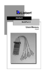
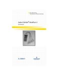
1
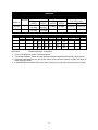
Little Glass House
Integrated Secured Protection
for Network Equipment
USER MANUAL
English
SAFETY INSTRUCTIONS ................................................................................................................................... 3
GLOSSARY OF SYMBOLS................................................................................................................................. 3
INTRODUCTION ................................................................................................................................................. 4
UPS SUPPORT................................................................................................................................................ 5
INSTALLATION................................................................................................................................................... 5
UNLOADING AND INSPECTION ..................................................................................................................... 5
LOCATION....................................................................................................................................................... 5
INSTALLATION CONNECTIONS ..................................................................................................................... 6
INSTALLING CUSTOMER EQUIPMENT.......................................................................................................... 6
START-UP ....................................................................................................................................................... 7
OPERATION ....................................................................................................................................................... 8
ENVIRONMENTAL CONTROL MODULE (ECM) & UNINTERRUPTIBLE AIR SUPPLY™ (UAS)...................... 8
FORCED AIR COOLING (FAC)........................................................................................................................ 8
SITENET® INTEGRATOR® ............................................................................................................................. 8
SENSOR OPTIONS ......................................................................................................................................... 9
MAINTENANCE ................................................................................................................................................ 10
FILTER CLEANING........................................................................................................................................ 10
ECM REPLACEMENT.................................................................................................................................... 10
UPS REPLACEMENT .................................................................................................................................... 10
TABLES ............................................................................................................................................................ 11
FORCED AIR COOLING (FAC) PERFORMANCE DATA (WITH 30PPI FILTER) ............................................ 11
ENVIRONMENTAL COOLING MODULE (ECM) PERFORMANCE DATA....................................................... 11
FIXED SERVICE CONNECTION (AMPS)....................................................................................................... 12
MAX. AVAILABLE CUSTOMER EQUIPMENT AMPS ..................................................................................... 12
FULL LOAD AMP DRAW (230V - 50HZ) ......................................................................................................... 12
DRAWINGS....................................................................................................................................................... 13
TROUBLESHOOTING....................................................................................................................................... 23
Model Number Breakdown
RD
Enclosure
Rack Width
RD=24" Rack
HD=19" Rack
78 38
Enclosure
Height/ Depth
78" Height
72" Height
38" Depth
34" Depth
(Nominal)
M
Main or
Cluster
M = Main
C = Cluster
D
Primary Cooling
System
A = FAC-190
B = FAC-360
C = ECM-42
D = ECM-62
E = N/A
F = ECM-80
2
E
UPS
Rack-Mount
0 = None
A = N/A
B = N/A
C = GXT-1000
D = N/A
E = GXT-1500
F = N/A
G = GXT-2000
K
Input Power
K = 120V/60Hz/1PH
S = 230V/50Hz/1PH
SAVE THESE IMPORTANT SAFETY INSTRUCTIONS
WARNING: Do not attempt to service this product yourself. Opening or removing
covers will risk exposure to dangerous voltages. Refer all servicing to qualified service
personnel.
1. SAVE THESE INSTRUCTIONS.
THIS
MANUAL
CONTAINS
IMPORTANT
SAFETY INSTRUCTIONS. Read all safety
and operating instructions before operating
the Little Glass House (LGH). Adhere to all
warnings on the unit and in this manual.
Follow all operating and user instructions.
9. Operate the LGH in an indoor environment
only with an ambient temperature range of
0° C to +40° C (32° F to +104° F). Install it
in a clean environment, free from moisture,
flammable liquids, gasses, or corrosive
substances.
10. Storing magnetic media on top of the LGH
may result in data loss or corruption.
CONSERVER
CES
INSTRUCTIONS.
CETTE
NOTICE
CONTIENT
DES
INSTRUCTIONS
IMPORTANTES
CONCERNANT LA SÉCURITÉ.
11. Do not stand beverage containers on the
LGH.
12. This equipment can be operated
individuals without previous training.
2. This
product
is
designed
for
Commercial/Industrial use only. It is not
intended for use with life support and other
designated “critical” devices. Maximum load
must not exceed that shown on the LGH
rating label.
If uncertain, consult your
dealer. See Limited Warranty.
by
13. Qualified Personnel should be consulted
for the following conditions:
- Power cable is damaged
- Liquid spilled into product
- LGH does not operate when operating
instructions have been followed.
3. The LGH must be permanently connected to
the input AC/mains supply and protected by
a suitable circuit breaker or fuse.
Glossary of Symbols
4. The LGH must be powered from a suitable
single phase supply rated in accordance
with the equipment data plate, and must be
suitably grounded/earthed.
Indicates weight
5. The utility/mains supply socket or means of
isolation must be within 2 meters of the
equipment and accessible to the operator.
Indicates a Ground/Earth
connection
6. This
equipment
complies
with
the
requirements of the EMC Directive
89/336/EEC and the published technical
standards. Continued compliance requires
installation in accordance with these
instructions and the use of manufacturer
approved accessories with output cables not
exceeding 10 meters (30 ft.) in length. Use
a shielded cable for the external
communications interface.
Indicates a Warning - Hazardous
Voltage Present
Consult the user’s manual for
additional information
Indicates Caution: Note the
accompanying instruction
7. Route power supply cords so they are not
walked on or pinched.
8. Never block or insert any object into the
ventilation holes or other openings.
Maintain a minimum clearance of 305 mm
(12 inches) in front and rear of the LGH for
proper air flow and cooling.
Indicates alternating current
3
INTRODUCTION
ENVIRONMENTAL CONTROL
Your Liebert Little Glass House™ (LGH) will
provide a secure controlled environment in a
single factory assembled enclosure.
The
integrated/matched models are designed to
control the environment and provide smooth
reliable power so that your sensitive computer
and network equipment will provide the reliable
performance you depend upon for your business
operations.
The Uninterruptible Air Supply™ (UAS) consists
of an Environmental Control Module (ECM) and
a Back-up Cooling Fan. The ECM is normally
sized to match the capacity of the UPS module
plus heat transmitted into the LGH. Three ECM
modules, ECM-42, ECM-62, and ECM-80 are
available. Air is controlled and circulated within
the enclosure. Outside (ambient) air is used to
remove heat from the enclosure through the air
cooled condenser. Two-speed fans are used to
provide quiet operation. At rated maximum
ambient conditions, the temperature inside the
enclosure will be from 70° to 95°F (21 to 35°C),
depending on the electronics load. If the internal
cabinet temperature reaches 100°F (38°C) -- for
example, during a power failure -- the Back-up
Cooling Fan operated on UPS battery power will
flow filtered ambient air through the enclosure.
The Little Glass House is completely factory
assembled and tested, ready for you to install
your equipment and plug the unit into a 120 V~/
60 Hz or 230 V~/ 50 Hz dedicated outlet. For 60
Hz
models,
the
required
power
receptacle/socket may be 15, 20, or 30 Amps,
depending on your selected LGH. Models with
60 Hz ECM-80 uses two input power
connections, with one 20 Amp plug for the ECM80 and the other plug either 15 or 20 Amps
depending on the UPS model. For 50 Hz
models, a power cord is included for connection
to a customer supplied plug.
The Back-up Cooling Fan is standard on UAS
models. All UAS or ECM models require a
clearance of 12 inches (305 mm) both on top
and rear of the LGH for proper airflow. The 50
Hz back-up cooling options have an On/Off (O/I)
switch located in the inlet channel to the ECM
condenser coil. This switch should be on during
normal operation.
Refer to drawings and tables in this manual for
dimensions, environmental performance data,
and input power requirements. Refer to the
separate UPS manual for UPS performance
details.
If environmental control as previously described
is not required, Forced Air Cooling (FAC) is
available. Filtered ambient air is drawn through
the enclosure from the bottom front to the top
rear.
A two-speed fan is controlled by a
thermostat factory set at 80°F (27°C), which
measures air entering the unit. The two-speed
fan design provides quiet low-speed operation
below the thermostat set point. A single fan
(nominally rated at 190 CFM - 323 CMH) or dual
fans (nominally rated at 360 CFM - 611 CMH)
can be provided. A clearance of 12 inches (305
mm) is required both on top and rear of the LGH
for FAC models.
ENCLOSURE
The enclosure can accommodate shelf mounted
or rack mounted equipment, on either 19 or 24
inch punched rails (per EIA-310). The 19 inch
rack cabinets are 25 inches (635 mm) wide.
Cabinets with 24 inch racks are 30 inches (765
mm) wide. The enclosures can be nominal 72
or 78 inches (1830 or 1980 mm) high, and 34 or
38 inches (865 or 965 mm) deep. The unit is
mounted on casters and leveling feet. Interior
insulation is provided in models with
Environmental Control Module (ECM) cooling.
A solid panel (metal) front door is standard. A
smoked plastic front window is available to
maintain enclosure security while allowing you to
monitor equipment status.
The rear door
provides convenient access to customer wiring.
Two horizontal cable entrance raceways are
provided.
An optional internal cable
management raceway (vertical) is available.
Both doors have a key lock and a four point
latch.
4
UPS SUPPORT
INSTALLATION
The integrated/matched models include an
uninterruptible power supply (UPS) module to
provide surge suppression, regulated voltage
and frequency, and battery backed operating
time. This will allow you to perform a controlled
computer shutdown in the event of a
utility/mains power failure. The UPS supplied is
a rackmount model factory installed in the rack
rails and supported by brackets. UPS models
available include the on-line Liebert UPStation
GXT in 1000, 1500, or 2000 VA capacity. Refer
to the separate UPS manual for more details.
UNLOADING AND INSPECTION
Refer to drawing on page 13 for dimensions,
weight, and connection locations for your model.
Carefully unload your new Little Glass House™
(LGH) from the box and from the pallet. Note
the unit weight for your model. Use at least two
people for safe handling.
Unloading Procedure:
1. Cut bands. Use caution.
2. Remove cardboard and plastic.
3. Remove two 2 X 4’s from sides of unit.
4. Remove one 2 X 6 from rear of unit.
5. Remove four lag bolts from front of skid.
6. Remove one 2 X 6 from front of unit.
7. Slide 4 X 4 runner from under front of skid.
8. Move unit forward until skid and unit tilt.
9. Roll unit off front of skid.
EQUIPMENT MOUNTING OPTIONS
Optional equipment mounting hardware is
available including a fixed shelf, a pullout shelf,
19 inch to 24 inch rack rail adapters, threaded
adapters, adjustable position rack rails and
Compaq® adapters.
Each optional kit is
supplied with installation hardware.
Open the doors and locate the keys, which are
shipped inside the enclosure. The front and rear
locks use the same key. To open either door,
turn key clockwise 1/8 turn to unlock, lift bottom
of handle, then turn handle away from unit 1/4
turn to open.
CLUSTERED CONFIGURATIONS
For applications requiring more than one
enclosure, an optional Cluster Enclosure is
available. In addition to providing more space
for electronic equipment, this configuration
allows cabinets to be connected side-by-side so
that an ECM, FAC, or UPS can serve more than
one cabinet. Refer to separate installation
instructions provided with the cluster cabinet.
Inspect exterior and interior for shipping
damage. If any damage is noted, file a claim
with the shipper and inform your Liebert
supplier.
LOCATION
The unit should be located in a room where the
ambient air is adequately ventilated for the
peripheral equipment (printers, etc.) outside the
LGH.
The maximum ambient operating
condition for 60 Hz units is 105°F (40°C). For 50
Hz units, maximum ambient temperature is
100°F (38°C). Place unit on a level surface, or
use leveling feet to level the unit.
HEAT REJECTION DUCT
For applications in confined spaces (equipment
rooms or closets), an optional Heat Rejection
Duct is available to connect the Little Glass
House to a ducted ventilation system. Refer to
drawing on page 19 in this manual for details.
Note the dimensions for your selected Little
Glass House model to determine space
required. Units with UAS or ECM require a
clearance of 12 inches (305 mm) both on top
and rear of the LGH. Units with Forced Air
Cooling (FAC) require 12 inches (305 mm) of
top and rear clearance. Air is drawn through the
front intake louver and discharged at the rear.
Do not block air flow at the front or the rear. The
optional Heat Rejection Duct will require
additional rear clearance.
5
up Cooling Fan operating) and Dirty Air Filter
(filter is clogged and requires cleaning).
Customer connection is two compression lug
terminals inside the rear of the unit. These
normally open contacts are rated for 40
milliAmps at 30 volts maximum (Class 2 wiring).
ALCOVE INSTALLATION
Rear
Top
Sides
Bottom
ECM
12"
12"
0"
ECM/UAS
12"
12"
0"
Non-Restricted
FAC
12"
12"
0"
A contact is provided on the rear of the ECM to
indicate power to the compressor (Compressor
on/off). This normally open contact is rated for
0.5 Amp at 120 V~.
The unit can be rolled forward on casters for
easy access to Liebert and customer wiring at
the rear of the unit. To open the front door,
clearance required depends on the size of your
unit. No side clearance is needed.
A control contact is provided inside the ECM
(under access plate at top left rear) for remote
shutdown/ startup. To use, replace jumper on 37
and 38 with a normally open non-powered
switch, rated for 5 Amps at 120 V~.
For applications requiring more than one
enclosure, an optional Cluster Enclosure is
available. In addition to providing more space
for electronic equipment, this configuration
allows cabinets to be connected side-by-side so
that an ECM, FAC, or UPS can serve more than
one cabinet.
To allow communications between the UPS and
a LAN server or other computer system, the
available UPStation GXT is equipped with an
RS-232
interface
port.
Other
UPS
communication options are available, including
SNMP. Refer to the separate UPS manual for
details.
INSTALLATION CONNECTIONS
The Little Glass House is a self-contained unit.
The only required connection is for electric
power. For 60 Hz models, the power cord is 9
(2.7 m) feet long and has a NEMA 120 V~ plug,
sized for current (Amps) based on equipment
specified when ordered. For 50 Hz models, a
power cord is included for connection to a
customer supplied plug. The 60 Hz ECM-80
model uses two input power connections, with
one 20 Amp plug for the ECM-80 and the other
plug either 15 or 20 Amps depending on the
UPS model. Refer to table on page 11. The
LGH and its protected equipment should be on a
dedicated circuit and circuit breaker.
The optional SiteNet™ Integrator is a separate
rackmount unit which communicates status of
the UPS and Little Glass House (including
temperature/humidity and several contact
closures) in SNMP protocol to a network
management system.
No plumbing connections are required as ECM
condensate is evaporated into the heat rejection
airstream. A condensate drain tube (3/8 inch
O.D. copper) is provided with ECM, but a
customer connection is not necessary. The
drain connection may need to be used in
exceptional situations, such as if a door is left
open for longer than 15 minutes while the ECM
is operating.
Do not defeat ground/earth connections
between the utility/mains outlet and the Little
Glass House. All plug receptacles/sockets in
the vicinity of where the LGH will be used must
be a ground/earth type and grounded/earthed
with an insulated ground/earth conductor of
identical size, insulation material, and thickness
to
the
grounded/earthed
and
ungrounded/earthed supply conductors which is
grounded/earthed to ground/earth at the service
equipment or separately derived source.
INSTALLING CUSTOMER EQUIPMENT
NOTE: The utility/mains output must have the
neutral and ground/earth bonded, per the
National Electrical Code, to prevent damage to
the UPS. Damage related to faulty utility/mains
wiring is not covered by Liebert warranty.
The Little Glass House can accommodate rack
mounted or freestanding computer and network
equipment. The unit contains 19 or 24 inch
punched rack rails (per EIA 310), depending on
model selected. Rack rails are provided at the
front and rear of the enclosure. Mounting
hardware
available
from
your
Liebert
representative includes a fixed shelf, a pullout
shelf, 19 inch to 24 inch rack rail adapters,
threaded adapters, adjustable position rack rails
and Compaq® adapters. Each optional kit is
supplied with installation hardware.
Contacts are provided to annunciate two alarms:
High Temperature (100°F - 38°C internal, Back-
To maintain unit center of gravity as low as
possible, install customer equipment from the
6
START-UP
bottom up, starting with the heavier units. Leave
available space (if any) at the top of the
enclosure.
CAUTION: To avoid tipping the unit when it
being moved, push slowly on the lower part
the enclosure. After customer equipment
installed, the Little Glass House may have
high center of gravity.
Before applying power, make sure the computer
equipment and power switches are in the OFF
position. Plug the Little Glass House power
cable
into
the
customer
provided
receptacles/sockets. Be certain there are no
obstructions (such as wires, conduit, or trash) to
the front or sides of the ECM. Make sure all
doors shut and seal properly. Roll the unit into
final position according to the location section on
page 4. If heat rejection duct option is included,
be sure there are no loops or kinks in the duct.
is
of
is
a
The LGH can support an electrical load based
on the UPS capacity. For integrated/matched
models, the Environmental Control Module is
normally sized to match the capacity of the UPS
plus heat transmitted into the enclosure. A
larger UPS can be supplied for longer battery
time. For 60 Hz units without a UPS, the
customer specifies maximum Amp load to
determine proper NEMA power plug rating.
Turn on the Environmental Control Module
(ECM), or Forced Air Cooling system (FAC).
Then turn on the UPS, if included. If UPS status
indication is normal, turn on your computer and
network equipment. The UPS will immediately
supply regulated power. Battery back-up will be
available after batteries are fully charged.
NOTE: To charge the UPS batteries before
using the unit, you can apply power to the UPS
module while you are installing your equipment.
Install your critical equipment in the Little Glass
House. Use the two vertical channels at the rear
of the unit for routing customer wiring. Power
and communication wiring should be kept
separate as much as possible.
The 60Hz Environmental Control Module has a
lighted power switch. The power switch for the
50 Hz models is the circuit breaker “B" on the
electric service assembly. ECM temperature
and capacity controls, including hot gas bypass,
are factory set. The FAC models have a
temperature switch factory set at 80°F (27°C),
which measures air entering the unit. The front
air filter requires periodic cleaning.
CAUTION: To avoid excessive condensation,
turn off the Environmental Control Module any
time an LGH door will be open for more than 15
minutes.
The optional power strip includes a circuit
breaker. The 60 Hz model includes 10 5-15R 15
Amp, 120 V~ receptacles/sockets. The 50 Hz
model includes 10 CEE22 (IEC320) 10 Amp,
250 V~ receptacles/sockets. The power strip is
protected by the UPS if a UPS is included. As
viewed from the rear, the ten power outlets are
on the right side. Power wiring is intended to be
routed on the right. Communication and control
wiring should be routed to the left side.
The UPS module has user friendly controls and
indicators. Refer to separate UPS manual for
details of UPS operation and LED indicators.
CAUTION: To maintain UPS battery capacity, do
not store Little Glass House for more than 6
months without applying power.
Provide enough length on customer supplied
cables to allow unit to be rolled forward for rear
access. Remember to connect a cable to the
Little Glass House alarm contacts if required for
your installation. Route customer wiring through
the two horizontal cable entrance raceways. An
optional internal cable management raceway
(vertical) is available.
Call your Liebert supplier if you have any
questions or problems during the installation or
operation of your Little Glass House.
7
OPERATION
FORCED AIR COOLING (FAC)
ENVIRONMENTAL CONTROL MODULE
(ECM) & UNINTERRUPTIBLE AIR SUPPLY™
(UAS)
Forced Air Cooling can be provided by a single
fan (nominally rated at 190 CFM - 323 CMH), or
by dual fans (nominally rated at 360 CFM - 611
CMH). The two-speed fans are activated by a
temperature switch.
Ambient air is drawn
through the filter at the bottom front of the unit,
and discharged at the top rear.
For
integrated/matched
models,
the
Environmental Control Module is normally sized
to match the capacity of the UPS module and
heat transmitted into the Little Glass House™.
The module is located at the bottom of the
enclosure.
Internal air is conditioned and
circulated within the enclosure.
Outside
(ambient) air is used to remove heat from the
enclosure through the air cooled condenser. The
outside air is drawn through a louver and filter at
the bottom front of the unit and is discharged at
the rear (near the bottom).
The ON/OFF control switch is located inside
the front door, on the left side. The same
control box includes the temperature switch
factory set at 80°F (27°C), which measures
air entering the unit. If the entering air
temperature goes above 80°F (27°C), the fan
speed switches from low to high.
The lighted ON/OFF switch is located inside the
front door, on the left side of the electrical panel
on 60 Hz models. For 50 Hz models, use circuit
breaker “B” of electrical service assembly for
ECM On/Off.
UNINTERRUPTIBLE POWER SUPPLY (UPS)
The Little Glass House may be supplied with
one of several Liebert UPS units, or with no
UPS. For integrated/matched models, the UPS
and ECM are normally sized with matched
capacities. A larger UPS can be supplied for
more battery time, but the connected electronics
load should not exceed the ECM rating.
At rated maximum ambient conditions, the
temperature inside the enclosure will be from
70° to 95°F (21 to 35°C), depending on the
electronics load. The two speed fans are factory
set to operate at the lower speed for quiet
operation when the outside air entering the
condenser is below 80°F (27°C).
The
compressor in the Environmental Control
Module will turn off if the internal cabinet
temperature goes below 65°F (18°C).
For LGH models supplied with a UPS, refer to
the separate UPS manual for operation and
specifications.
SITENET® INTEGRATOR®
Refer to the Integrator Electrical Connection
Diagram on page 21 for specifics regarding
installation.
The hot gas bypass valve is factory set so the
compressor will operate nearly continuously for
maximum compressor life.
This valve
modulates automatically to match compressor
capacity to the present load. Consult factory if
adjustment is desired.
The SiteNet Integrator is a separate rackmount
unit that communicates status of the UPS and
LGH. The option consists of a SiteNet Integrator
module that is typically mounted in the top of the
LGH cabinet.
In UAS systems, during an enclosure high
temperature condition (100°F - 38°C) a separate
Back-up Cooling Fan operated on UPS battery
power (if included) will use filtered ambient air to
cool the enclosure. This would occur only
during a power failure or an Environmental
Control Module failure. To annunciate a high
temp condition, an alarm beeper sounds and the
alarm contact closes (press Alarm Silence
switch to turn off beeper). Outside air is drawn
through a louver and filter at the bottom front of
the unit and is discharged at the rear (near the
top).
The SiteNet Integrator is powered by one or two
externally mounted power supplies. One is
standard, the second is optional. These power
supplies provide the 9VDC required to power the
Integrator module. One supply will be plugged
into the UPS or the UPS outlet strip located in
the rear hinge side of the cabinet. The output
cable is plugged into the SiteNet Integrator
Power Supply Main input receptacle/socket. The
(optional) second supply will be plugged into the
electrical service power inlet in the lower rear of
the LGH cabinet. The supply's output cable is
plugged into the SiteNet Integrator Power
Supply Aux input receptacle/socket.
8
rear of the ECM. A two-conductor control cable
is connected between the power supply terminal
strips marked "Close to Energize Relay R1" and
the Relay Output K1 terminal strip on the rear of
the SiteNet Integrator. When the relay output
contacts on the SiteNet Integrator close, the
relay in the power supply is energized closing
the normally open contacts and shorting
between terminals 37 & 38 in the rear of the
ECM. This will allow power to be applied to the
ECM and cause the ECM to begin operation if
the ECM On/Off switch is in the On position.
Consequently, de-energizing the relay will allow
the ECM to be turned off remotely by the SiteNet
Integrator.
An optional UPS status communication cable is
available that allows transmission of information
between the UPS and the SiteNet Integrator.
This cable will plug into the 25 pin D Type
connector on the rear of the UPS marked DB25P. The opposite end of the cable in plugged
into the 9 pin D Type receptacle on the rear of
the SiteNet Integrator marked UPS RS-232 DB9P.
SENSOR OPTIONS
Door Ajar -- This option consists of two normally
open switches that are mounted to the cabinet
front and rear frame supports. The switches will
indicate by the position of the doors (opened or
closed) as determined by the status of the drycontact inputs to which they are connected on
the rear of the SiteNet Integrator.
Smoke Detector Option -- A four-wire smoke
detector with normally open contacts, heat
sensor and sounder alarm is mounted in the top
of the LGH cabinet. The smoke detector is
power by a 24VDC power supply (*) mounted in
the frame channel of the LGH cabinet. The
power supply is normally powered from the UPS
(if available), but may be powered from
utility/mains by customer discretion. Power to
the smoke detector is supplied by a twoconductor cable between the power supply and
the smoke detector. A second two-conductor
cable connects between the smoke detector and
the Integrator dry-contact inputs. If smoke,
flame, or high temperature change are detected,
the normally open contacts of the smoke
detector will close to provide alarm status to the
Integrator. The smoke detector sounder alarm
will also activate. This alarm can be silenced
only by removing power from the smoke
detector. This is accomplished by unplugging
the smoke detector power supply.
*The smoke detector power supply is a general purpose
Temperature and Humidity Sensors (Internal
and External) -- The sensors allow monitoring
of temperature and humidity status by the
SiteNet Integrator. The internal option is for
installation inside the LGH cabinet and is
supplied with a 12 foot (3.6 m) cord for
connection between the temperature/humidity
sensor and the SiteNet Integrator. Refer to the
connection diagram for wiring specifics. The
external option is supplied with a 30 foot (0.1 m)
cord for monitoring of temperature humidity
status outside the LGH cabinet. The sensor and
connections for both options are identical.
Water Detect -- The water detect option
includes a Liquitect (LT-400S) dry contact
sensor mounted in the bottom of the LGH
cabinet. The sensor is powered by a 24 VDC
power supply mounted in the frame channel of
the LGH cabinet. (Multiple options may share
this same general power supply. The supply is
rated for 1.6 Amps at 24 VDC). The water
detector is connected to the dry-contact input on
the rear of the SiteNet Integrator by a 30 foot
two-conductor cable. The detector may be
relocated outside the LGH cabinet by user
discretion for external water detection.
supply that may be used to power any option requiring 24
VDC. Multiple options may share the same supply. The
supply is rated for 1.6 Amps at 24 VDC.
All the above options are available factory
installed with the order. The options are also
available for field installation. Field installed
options are shipped as kits containing the
sensors with appropriate mounting hardware,
cable, and cable restraint fixtures.
Field
installation requires hand tools for termination of
control cables and routing of the cables.
Remote ECM On-Off Control -- This option
allows on-off control of the ECM by the SiteNet
Integrator. It consists of a 24 VDC Power
Supply with Control Relay that is mounted in the
frame channel of the LGH cabinet. The 24 VDC
power supply may also be used to power other
options. A black SJ two-conductor (black & red)
cable is connected between the power supply
relay normally open contacts and the ECM
power terminal strip (terminals 37 & 38) in the
All other standard alarm signals provided by the
LGH (High Temp, Clogged Filter, Cooling
Status) are also pre-wired for monitoring by the
SiteNet Integrator.
9
MAINTENANCE
UPS REPLACEMENT
CAUTION: To avoid tipping the unit when it is
being moved, push slowly on the lower part of
the enclosure. After customer equipment is
installed, the Little Glass House™ may have a
high center of gravIty.
To remove the UPS for factory repairs:
-Turn off power. Unplug UPS from receptacle
inside rear of the Little Glass House.
-Unplug the power strip, ECM or FAC controls,
and any other equipment plugged into the UPS.
FILTER CLEANING
NOTE: Inspect the air filter periodically to
determine the necessary cleaning interval based
on conditions at your installation.
-Disconnect any optional communication cables.
If the air filter becomes dirty and clogged, the
alarm contact closes (no beeper alarm is
sounded). The filter is behind the louver at the
bottom of the front door. Remove two screws,
pull up the filter, clean with mild soapy water,
rinse, dry, and replace.
-Remove the UPS from the front of the LGH.
-Remove screws retaining the UPS.
-Install the replacement UPS.
PLUG WIRING
Line (L)
Neutral (N)
Ground/Earth (G)
ECM REPLACEMENT
TO REMOVE THE ECM FOR FACTORY
REPAIRS:
-Turn off power. Unplug Environmental Control
Module from receptacle inside rear of the Little
Glass House.
-Remove the screws retaining the access plate
at top left rear of ECM. Remove the plate and
tuck the ECM power cord and plug inside the
opening to allow the ECM to pass beneath the
UPS or mounted shelves. For models including
a UPS, do not replace this access panel until
after ECM has been removed.
-Models containing a 60 Hz ECM80 require the
removal of the plug from the ECM power cord.
Once removed the power cord strain relief may
be loosened to allow the power cord to slide
through when the ECM is withdrawn from the
cabinet.
Observe wiring polarity when
reinstalling the plug on the replacement unit.
-If connected, remove customer wiring to ECM
compressor power contact and/or remote
shutdown/startup contact.
-Remove four screws retaining the front
electrical panel. Pivot panel to the left. Cables
are long enough to move the box out of the way
so the Environmental Control Module can be
pulled forward after removing four rack mount
screws.
-Replace cable access cover on ECM. Package
unit for return to Liebert.
-Install the replacement ECM.
10
50 Hz
Brown
Blue
Gold
60 Hz
Black
White
Gold
TABLES
FORCED AIR COOLING (FAC) PERFORMANCE DATA (WITH 30PPI FILTER)
AIRFLOW (w/Filter)
SOUND LEVEL
INPUT POWER (1PH)
# FANS
FLA / WSA / OPD
HIGH
LOW
HIGH
LOW
MODEL #
SPEED
SPEED
SPEED
SPEED
120V/60Hz 220V/50Hz
190 CMF
90 CMF
FAC-190
1
61 dBa
47 dBa
0.5/15/15
0.5/15/15
112 CMH
53 CMH
360 CMF
175 CMF
FAC-360
2
59 dBa
49 dBa
1.0/15/15
1.0/15/15
212 CMH
103 CMH
ENVIRONMENTAL COOLING MODULE (ECM) PERFORMANCE DATA
MODEL
NUMBER
RATED
CAPACITY
BTUH/Watt
SUPPORT
LOAD
BTUH/Watt
RATED/MAX
AMBIENT
60Hz
50Hz
ECM-42
4200/1230
2730/800
ECM-62
6200/1815
4095/1200
ECM-80
8000/2345
5800/1700
105F
41C
105F
41C
105F
41C
ECM Notes:
100F
38C
100F
38C
100F
38C
HEIGHT
U
In/mm
In/mm
Rack
In/mm
TOTAL
HEAT REJ.
BTUH/Watt
6
10.5/
265
12.3/
310
15.8/
400
17.5/
445
22/
560
22/
560
19
27/
685
27/
685
29/
735
7625/
2235
11310/
3315
14605/
4280
7
9
DIMENSIONS
WIDTH
24
24
DEPTH
INPUT POWER (1PH)
WEIGHT
120V/60Hz
220V/50Hz
(lbs/Kg)
8/15/15
7/15/15
95/43
12/20/20
9/15/15
115/52
16/20/20
16/20/20
167/76
Standard Offerings - All Systems
1. 60Hz: R-22 refrigerant / 50Hz: R-134A refrigerant
2. Two-Speed Operation - Switch low-high speed on ambient temperature external to LGH enclosure
3. Automatic Load Matching: Hot gas by-pass factor set for minimum capacity; by-pass will adjust to
match supported loads
4. Condensate Re-evaporation & Removal: Drain connection only required if enclosure seal is violated.
11
Electrical Service / Connection
The 60 Hz LGH is provided with a single NEMA plug and cord input power connection (except for ECM80 systems).
60 Hz Systems with UPS - Service Connection
If a UPS is supplied, the system power rating and plug connection are fixed.
FIXED SERVICE CONNECTION (AMPS)
Cooling
UPS-GXT (VA)
System
1000
1500
2000
FAC-190
15
15
20
FAC-360
15
15
20
UAS/ECM-42
20
--UAS/ECM-62
30
30
-UAS/ECM-80*
ECM-80 - 20 Amp / UPS-Load - 20 Amp
*LGH ECM-80 systems provided with separate
ECM & UPS power connections.
60 Hz Systems with NO UPS - Service Connection Selection
If a UPS is not supplied, the system power rating and plug connection are customer selected based on
the Cooling System and customer Amp load.
MAX. AVAILABLE CUSTOMER EQUIPMENT AMPS
(based on customer selected Service Connection)
Cooling System
SERVICE CONNECTION
15 Amp
20 Amp
30 Amp
FAC-190
11.5
15.5
23.5
FAC-360
11
15
23
ECM-42 only
-8
16
UAS-42
-7
15
ECM-62 only
--12
UAS-62
--10
UAS/ECM-80*
---*Power strip is rated for 15 Amp service
50 Hz Systems with NO UPS or WITH UPS - Full Load Amp Draw
The 50 Hz LGH is provided with a cord for input power connection; an appropriate plug is to be field
supplied. Selection charts below are to be used to determine plug requirements per local codes.
FULL LOAD AMP DRAW (230V - 50Hz)
Cooling System
UPS
UPS-G (VA)
1000
1500
FAC-190
.5
4.5
6.5
FAC-360
1
5
7
UAS/ECM-42E only
7
11
-UAS/ECM-42E
7.5
11
-UAS/ECM-62E only
9
13
15
UAS/ECM-62E
9
13
15
UAS/ECM-80E
9
13
15
Note: Power strip is rated for 10 Amp service
12
2000
8.7
9.2
----17
DRAWINGS
13
14
15
16
17
18
19
20
TEMP. RISE PER CABINET, DEG. F
LGH RD/HD FORCED AIR CABINET TEMP. RISE
AT STANDARD AIR CONDITIONS
40
FAC-360(2 FAN) HIGH SPEED
FAC-190(1 FAN) HIGH SPEED
FAC-360(2 FAN) LOW SPEED
30
FAC-190(1 FAN) LOW SPEED
20
10
0
200
400
600
800
1000
1200
INTERNAL LOAD PER CABINET, WATTS
MINIMUM SPEED SET AT 2000 RPM
21
1400
INTEGRATOR POWER, UPS, & TERMINAL CONNECTIONS
22
TROUBLESHOOTING
PROBLEM
ECM Not Cooling
CAUSE
No Power
Filter Clogged
Refrigerant loss
Fans blowing warm air
Hot Gas Bypass Valve set
incorrectly
Squirrel cage free spinning on
evaporator or condenser blowers
Clogged Condenser coil
Compressor trips on thermal
overload.
Faulty Compressor
Condensate draining
continuously
Excessive opening of doors
Enclosure not properly sealed
Evaporator drain kinked or
clogged
Excessive vibration or
noise
Defective motor in blower
Defective squirrel cage in blower
Cabinet is excessively
hot
ECM is overloaded
Heat not rejected from room
ECM not cooling
UAS operation
23
SOLUTION
60 HZ: Verify F2 fuse not blown by
checking on/off switch. If not lit, fuse is
blown
50Hz: Verify breaker has not tripped.
Clean, or replace filter
Verify leak. If refrigerant system needs
repaired, replace ECM.
Set valve correctly per LGH handbook
Reattach and tighten squirrel cage to
blower shaft
Clean coil
Open LGH doors and let compressor cool.
Turn ECM on and verify compressor is
energized (humming). Verify cold air is
being discharged from evaporator
discharge (right side of ECM).
Verify Compressor has failed. Replace
ECM. If electrical component has failed
causing compressor not to run, replace
component.
Reduce the amount of opening. Suggest
external keyboard tray. Turn ECM off
when opening door.
Verify leak and fix or replace gasket
Remove ECM and verify plastic tubing is
attached to drain and not kinked or
clogged.
Replace motor
Replace squirrel cage, or reattach and
tighten to blower shaft.
Verify the correct UPS and load on UPS. If
no UPS; verify watt load of equipment
does not exceed ECM rating.
Verify LGH is located in room with air
circulation and heat rejected from ECM is
sufficiently removed from room.
See above
Verify UAS operation by jumpering
terminals on high temperature stat
Limited Warranty
(for U.S. Sales and Installations)
We are pleased that you have purchased the Little Glass House™ product to
enhance the environment and the reliability of the available AC power for
your sensitive electronic equipment.
Liebert Corporation warrants to the original user all parts that make up the
Little Glass House for a period of thirteen (13) months from the factory ship
date or proof of purchase date, including the LGH enclosure and the
Environmental Control Module (ECM). The UPS module and batteries have
a parts warranty of twenty-four (24) months from factory ship date or proof of
purchase date. Complete removal of the UPS and Environmental Control
Module is required for warranty field replacement. Extended warranty
contracts are available for the Little Glass House.
Note that the limited warranty for the Little Glass House is for parts only.
NOTE: UPS Warranty is void if the battery is allowed to discharge below the
minimum battery voltage cutoff point.
CAUTION: To prevent excessive battery discharge. DO NOT leave the UPS
POWER switch ON for more than 2 days without AC/mains power being
supplied to the UPS. The battery must be recharged every 4 to 6 months if
not in use.
Circuit breaker resetting is not covered by this warranty and may indicate use
beyond capability of the product. No warranty applies to products which have
been abused, mishandled, modified, damaged by act of God or source
external to the product, repaired by others, or which have product serial
numbers removed or altered.
There are no warranties other than that described herein. In no event will
Liebert be responsible beyond the purchase price of the product. SELLER
DISCLAIMS ANY IMPLIED WARRANTY OF MERCHANTABILITY OF THE
GOODS OR THE FITNESS OF THE GOODS FOR ANY INTENDED
PURPOSES.
LIEBERT ASSUMES NO RESPONSIBILITY FOR INCIDENTAL OR
CONSEQUENTIAL DAMAGES, INCLUDING WITHOUT LIMITATION, LOSS
OF USE, PROFIT, OR INCOME.
To make a warranty claim for replacement of a part/module, first call your
Liebert supplier with the unit model number and serial number. He will obtain
the required warranty return authorization from Liebert Corporation.
Customer is to package and ship the defective module or part to Liebert as
outlined on the Warranty Return Tag. The Warranty Return Tag needs to be
completed with description of defect, installer's name and telephone number,
and must accompany the defective module or part back to Liebert. The
Warranty Return Tag is included with the packing of the new or reconditioned
part from Liebert.
24
1050 Dearborn Drive
Columbus, OH 43229
614-888-0246
Little Glass House
Integrated Secured Protection
for Network Equipment
Technical Support
U.S.A.
Outside the U.S.A.
U.K.
France
Germany
Italy
Netherlands
E-mail
Web site
Worldwide FAX tech support
1-800-222-5877
614-841-6755
+44 (0) 1793 553355
+33 (0) 1 43 60 01 77
+49 89 99 19 220
+39 2 98250 1
+31 (0) 475 503333
[email protected]
http://www.liebert.com
+614-841-5471
The Company Behind The Products
While every precaution has been taken
to ensure accuracy and completeness of
this literature, Liebert Corporation
assumes
no
responsibility,
and
disclaims all liability for damages
resulting from use of this information or
for any errors or omissions.
With more than 500,000 installations around
the globe, Liebert is the world leader in
computer protection systems.
Since its
founding in 1965, Liebert has developed a
complete range of support and protection
systems for sensitive electronics:
§
Environmental systems: close-control
conditioning from 1.5 to 60 tons.
air
§
Power conditioning and UPS with power
ranges from 250 VA to more than 1000 kVA.
§
Integrated systems that provide both
environmental and power protection in a
single, flexible package.
§
Monitoring and control — on-site or remote —
from systems of any size or location.
§
Service and support, through more than 100
service centers around the world, and a 24hour Customer Response Center.
©1997 Liebert Corporation All rights
reserved
throughout
the
world.
Specifications subject to change without
notice.
® Liebert and the Liebert logo are
registered
trademarks
of
Liebert
Corporation. All names referred to are
trademarks or registered trademarks of
their respective owners.
SL-15050 (5/97) Rev. 4
25