1
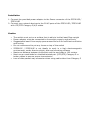
Package Contents
•
•
•
One ZFS3015P / ZFS3018P
One Quick Installation Guide
One Power Adapter
Contact your local authorized reseller or the store purchased from for any items
damaged and/or missing.
Top Panel
LED indicators
LED
Power
Status Operation
Green Steady: Power is ON
LNK/ACT
Steady: Network cable connected and connection established
Green Flash: Data packets are transmitting
Off: Network cable is unplug
Diagram
a. ZFS3015P
Note: Power Connector is on the marked side of ZFS3015P
b. ZFS3018P
Note: Power Connector is on the marked side of ZFS3018P
Rear Panel
a. ZFS3015P
5 RJ-45 ports
b. ZFS3018P
8 RJ-45 ports
Installation
1. Connect the provided power adapter to the Power connector of the ZFS3015P /
ZFS3018P
2. Connect your network devices to the RJ-45 ports of the ZFS3015P / ZFS3018P
with UTP/STP Category 3/4/5 cables
Caution
•
•
•
•
•
•
•
•
The switch must put on a surface that is able to hold at least 5kgs weight
Power adapter must be connected to the switch properly and securely
Suggested at least 10cm empty space around the unit for sufficient ventilation
and cooling
Do not recommend to put any items on top of the switch
ZFS3015P / ZFS3018P is not ideally to work in a high electromagnetic
environment, under direct sunlight, dust and vibrating surfaces
Maximum distance between the switch and the end node is 100 meters
Must use an unshielded or shielded twisted-pair (UTP/STP) Category 5 or
better cables to ensure proper transmission
Loss of data packet may encounter when using cable other than Category 5
Troubleshooting
1. Check the power adapter and power wall-jet to make sure they are function
properly. Check if the switch is turned-ON and power LED is steady.
2. Check all cable connections between computer and the switch to make sure
they are connected properly.
3. Maximum distance is 100 meters from the switch to end nodes.
4. Link LED(s) is ON/flashing at the connected port(s) of the switch.
5. Test your computer’s network adapter to make sure it is installed and functioned
properly.
6. Check issues such as network collisions, domain limitations, and other physical
installation aspects. Make sure they all meet IEEE standard network
installation requirements, more details can be found at www.ieee.org.
7. If problem still persists, write down your software/hardware configuration and
LED error indications and contact your local retailer or the store purchased for
further assistance.
8. If the provided power adapter is missing, purchase 9V / 600mA power adapter
for replacement.