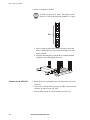
1
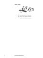
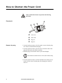
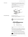
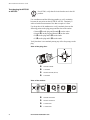
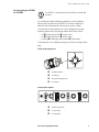
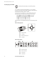
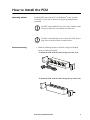
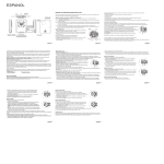
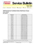
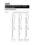
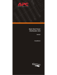
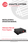
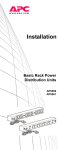
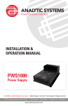
Rack Power Distribution Unit
Description
AP7580, AP7581, AP7582, AP7583, and AP7584 are 24 A Rack Power
Distribution Units (PDUs) that provide 120- or 208-volt power to rackmounted equipment.
AP7580, AP7581
28-foot NEMA L14-30 power cord
Four 20-amp circuit breakers
AP7580: Four NEMA L5-20 outlets
AP7581: Four NEMA L6-20 outlets
AP7582
28-foot NEMA L14-30 power cord
Two 20-amp circuit breakers
Twelve NEMA 5-20 outlets
AP7583, AP7584
28-foot NEMA L14-30 power cord
AP7583: Four NEMA L5-30 outlets
AP7584: Four NEMA L6-30 outlets
2
Rack Power Distribution Unit
Safety and Grounding
Read the following information before installing or operating your APC
Power Distribution Unit (PDU):
• The PDU is intended only for use with four-wire grounded
connections on APC Uninterruptible Power Supplies (UPSs). Do
not plug the PDU into an electrical outlet or other device.
• This PDU is intended for indoor use only.
• Do not install this PDU where excessive moisture or heat is
present.
• Never install any wiring, equipment, or PDUs during a lightning
storm.
• Do not use extension cords or adapters with this PDU.
• Do not work alone under hazardous conditions.
• Check that the power cord, plug, and socket are in good condition.
• Disconnect the PDU from the power outlet before you install or
connect equipment to reduce the risk of electric shock when you
cannot verify grounding. Reconnect the PDU to the power outlet
only after you make all connections.
• Install the PDU so that the power plug may be disconnected for
service.
• Install the PDU so that there is not an uneven mechanical load.
• Follow the nameplate ratings when connecting equipment to the
supply circuit. Do not overload the circuits. An overload condition
could put your over-current protection at risk or cause problems
with your supply wiring.
Risk of electrical shock. Use only the supplied hardware to
attach the mounting brackets.
Caution
The Rack PDUs are to be used only with InfraStruXure
Type A systems.
Note
Rack Power Distribution Unit
3
How to Shorten the Power Cord
Only certified electricians can perform the following
procedure.
Warning
Plug layout
Remove the plug
Cord sleeve
Strain relief
Plug case
Plug face
1. Loosen, but do not remove, the four captive screws from the plug
face until it is detatched from the plug.
2. Loosen, but do not remove, the four screws from the sides of the
plug until the cord easily slides in and out.
3. Slide the plug case down the cord to your desired length.
The cord must remain at least 4.9 feet (58.8 inches) long.
Note
4. Loosen, but do not remove, all four terminal screws until you can
remove all four wires from the plug. Set the plug face aside for
later use.
4
Rack Power Distribution Unit
How to Shorten the Power Cord
Cut the cord
1. Cut the outer cord sleeve to the desired length. Be careful not to cut
through the four wire bundles. The cord must remain at least
4.9 feet (58.8 inches) long from unit to end. Remove the cut sleeve
from the wire bundles.
2. Cut each wire bundle, making sure each is approximately 1.5
inches from the end of the cord sleeve.
3. Strip approximately 0.5 inches of insulation from each wire
bundle.
Reassemble the plug
1. Twist together any loose wires.
2. Fully insert each wire into its coordinating terminal on the plug
face before you tighten the terminal screw.
Insert only the bare copper wires into the terminals.
Do not tin the wires that hold the strands together.
Note
Wire color
Terminal
Red
Terminal marked “Y”
Black
Terminal marked “X”
Green
Ground pin, has a green screw
White
No markings, has a silver prong
3. Tighten the terminal screws to a minimum torque of 18 inchpounds.
4. Slide the plastic plug case back around the face of the plug. Align
the tab on the case with the corresponding opening on the plug
face. Secure the case by tightening two of the screws in the side of
the case to a minimum torque of 10 inch-pounds.
5. Reattach the strain relief to the plug, using the remaining two
screws. Tighten the screws to a torque of 16 to 20 inch-pounds.
Verify that the plug is connected properly by performing
the test procedures on page 6 (for AP7580 or AP7583),
page 7 (for AP7581 or AP7584), or page 8 (for AP7582).
Rack Power Distribution Unit
5
How to Shorten the Power Cord
Test the plug for AP7580
or AP7583
For AP7580, verify that all circuit breakers are in the ON
position.
Note
Use a multimeter and the following graphics to verify continuity
between the test points on the AP7580 or AP7583. Continuity is
achieved with a measurement of less than or equal to 1 Ohm.
Use the probes of the multimeter to verify continuity between the
following points on the plug prongs and the slots on the outlets:
• Ground (J) on the plug and Ground (J) on the outlet
• Neutral (Q) on the plug and Neutral (Q) on the outlet
• X ([) on the plug and X ([) on the outlet
• Y (\) on the plug and Y (\) on the outlet
Verify that there is no continuity among any of the four prongs on the
plug.
View of the plug face:
\
Q
J
[
J
Ground terminal
\
Y terminal
Q
Neutral terminal (Silver)
[
X terminal
View of the outlets:
J
Q
ON
ON
[
6
ON
\
J
Ground connection
Q
Neutral connection
[
X connection
\
Y connection
Rack Power Distribution Unit
ON
How to Shorten the Power Cord
Test the plug for AP7581
or AP7584
For AP7581, verify that all circuit breakers are in the ON
position.
Note
Use a multimeter and the following graphics to verify continuity
between the test points on the AP7581 or AP7584. Continuity is
achieved with a measurement of less than or equal to 1 Ohm.
Use the probes of the multimeter to verify continuity between the
following points on the plug prongs and the slots on the outlets:
• X ([) on the plug and X ([) on the outlet
• Y (\) on the plug and Y (\) on the outlet
• Ground (J) on the plug and Ground (J) on the outlet
Verify that there is no continuity among any of the four prongs on the
plug.
View of the plug face:
\
Q
J
[
J
Ground terminal
\
Y terminal
Q
Neutral terminal (Silver)
[
X terminal
View of the outlets:
J
[
ON
ON
ON
ON
\
J
Ground connection
\
Y connection
[
X connection
Rack Power Distribution Unit
7
How to Shorten the Power Cord
Test the plug for AP7582
Verify that all circuit breakers are in the ON position.
Note
Use a multimeter and the following graphics to verify continuity
between the test points on the AP7582. Continuity is achieved with a
measurement of less than or equal to 1 Ohm.
Use the probes of the multimeter to verify continuity between the
following points on the plug prongs and the slots on the outlets:
• Ground (J) on the plug and Ground (J) on the outlet
• Neutral (Q) on the plug and Neutral (Q) on the outlet
• X ([) on the plug and X ([) on the outlet
• Y (\) on the plug and Y (\) on the outlet
Verify that there is no continuity among any of the four prongs on the
plug.
View of the plug face:
\
Q
J
[
J
Ground terminal
\
Y terminal
Q
Neutral terminal (Silver)
[
X terminal
View of the outlets:
J Q
[
ON
8
\
ON
J
Ground connection
Q
Neutral connection
[
X connection
\
Y connection
Rack Power Distribution Unit
How to Install the PDU
Mounting options
Install the PDU in the bottom 2U of a NetShelter® or any standard
19-inch EIA-310-D rack or enclosure, using the mounting brackets
(provided).
The PDU can be installed in one of two ways, with the outlets
facing out of the rack or toward the roof of the rack.
Note
The PDU is intended only for use with an APC UPS. Do not
plug it into an electrical outlet or another device.
Note
Bracket-mounting
1. Attach the mounting brackets to the PDU, using four flat-head
screws per bracket (provided).
- To mount the PDU with the outlets facing out of the rack:
- To mount the PDU with the outlets facing the top of the rack:
Rack Power Distribution Unit
9
How to Install the PDU
2. Choose a location for the PDU.
The PDU occupies two U-spaces. The numbers on the
enclosure’s vertical rail denote the middle of a U-space.
Note
2U
a. Insert a caged nut (provided with the enclosure) above and
below a notched hole on each vertical mounting rail in your
chosen location.
b. Align the mounting holes of the brackets with the installed
caged nuts. Insert and tighten the screws.
Connect to an APC UPS
1. Route the power cord through one of the slots on the roof of the
enclosure.
2. If necessary, route the PDU cord across a ladder connected to the
enclosure to connect to an APC UPS.
3. Plug the PDU into the L14 outlet on the rear of the UPS.
10
Rack Power Distribution Unit
Specifications
Electrical
Nominal input voltage
120 or 208 V
Input frequency
50 or 60 Hz
Input connectors
NEMA L14-30 plug
Output connectors
AP7580: Four NEMA L5-20 outlets
AP7581: Four NEMA L6-20 outlets
AP7582: Twelve NEMA 5-20 outlets
AP7583: Four NEMA L5-30 outlets
AP7584: Four NEMA L6-30 outlets
Maximum total current draw 24 A
Physical
Size (H × W × D)
3.50 ×17.20×3.50 in
(8.89×43.69×8.89 cm)
Weight
14.0 lb (6.4 kg)
Shipping weight
16.0 lb (7.3 kg)
Environmental
Elevation (above MSL)
Operating
Storage
0–10,000 ft (0–3000 m)
0–50,000 ft (0–15 000 m)
Temperature
Operating
Storage
0 to 45° C (32 to 115° F)
–25 to 65° C (–13 to 149° F)
Humidity
Operating
Storage
0–95% RH Non-condensing
0–95% RH Non-condensing
Compliance
Safety verification
UL, cUL
Rack Power Distribution Unit
11
Warranty and Service
Limited warranty
APC warrants the PDU to be free from defects in materials and
workmanship for a period of two years from the date of purchase. Its
obligation under this warranty is limited to repairing or replacing, at its
own sole option, any such defective products. This warranty does not
apply to equipment that has been damaged by accident, negligence, or
misapplication or has been altered or modified in any way. This
warranty applies only to the original purchaser.
Warranty limitations
Except as provided herein, APC makes no warranties, express or
implied, including warranties of merchantability and fitness for a
particular purpose. Some jurisdictions do not permit limitation or
exclusion of implied warranties; therefore, the aforesaid limitation(s) or
exclusion(s) may not apply to the purchaser.
Except as provided above, in no event will APC be liable for direct,
indirect, special, incidental, or consequential damages arising out of
the use of this product, even if advised of the possibility of such
damage.
Specifically, APC is not liable for any costs, such as lost profits or
revenue, loss of equipment, loss of use of equipment, loss of software,
loss of data, costs of substitutes, claims by third parties, or otherwise.
This warranty gives you specific legal rights and you may also have
other rights, which vary according to jurisdiction.
Obtaining service
To obtain support for problems with your PDU:
0
1. Note the serial number and date of purchase. The serial number is
located on the bottom of the PDU.
2. Contact Customer Support at a phone number located on the back
cover. A technician will try to help you solve the problem by
phone.
3. If you must return the product, the technician will give you a return
material authorization (RMA) number. If the warranty expired, you
will be charged for repair or replacement.
4. Pack the unit carefully. The warranty does not cover damage
sustained in transit. Enclose a letter with your name, address, RMA
number and daytime phone number; a copy of the sales receipt;
and a check as payment, if applicable.
5. Mark the RMA number clearly on the outside of the shipping
carton.
6. Ship by insured, prepaid carrier to the address provided by the
Customer Support technician.
12
Rack Power Distribution Unit
Life-Support Policy
General policy
American Power Conversion (APC) does not recommend the use of any
of its products in the following situations:
• In life-support applications where failure or malfunction of the
APC product can be reasonably expected to cause failure of the
life-support device or to affect significantly its safety or
effectiveness.
• In direct patient care.
APC will not knowingly sell its products for use in such applications
unless it receives in writing assurances satisfactory to APC that (a) the
risks of injury or damage have been minimized, (b) the customer
assumes all such risks, and (c) the liability of American Power
Conversion is adequately protected under the circumstances.
Examples of life-support
devices
The term life-support device includes but is not limited to neonatal
oxygen analyzers, nerve stimulators (whether used for anesthesia, pain
relief, or other purposes), autotransfusion devices, blood pumps,
defibrillators, arrhythmia detectors and alarms, pacemakers,
hemodialysis systems, peritoneal dialysis systems, neonatal ventilator
incubators, ventilators (for adults and infants), anesthesia ventilators,
infusion pumps, and any other devices designated as “critical” by the
U.S. FDA.
Hospital-grade wiring devices and leakage current protection may be
ordered as options on many APC UPS systems. APC does not claim that
units with these modifications are certified or listed as hospital-grade by
APC or any other organization. Therefore these units do not meet the
requirements for use in direct patient care.
Rack Power Distribution Unit
13
APC Worldwide Customer Support
Customer support for this or any other APC product is available at no charge in any of the following ways:
• Visit the APC Web site to find answers to frequently asked questions (FAQs), to access documents in the APC
Knowledge Base, and to submit customer support requests.
– www.apc.com (Corporate Headquarters)
Connect to localized APC Web sites for specific countries, each of which provides customer support
information.
– www.apc.com/support/
Global support with FAQs, knowledge base, and e-support.
• Contact an APC Customer Support center by telephone or e-mail.
– Regional centers:
Direct InfraStruXure Customer Support
fif
(1)(877)537-0607 (toll free)
APC headquarters U.S., Canada
(1)(800)800-4272 (toll free)
Latin America
(1)(401)789-5735 (USA)
Europe, Middle East, Africa
(353)(91)702055 (Ireland)
Japan
(0) 35434-2021
Australia, New Zealand, South Pacífic
(61) (2) 9955 9366 (Australia)
– Local, country-specific centers: go to www.apc.com/support/contact for contact information.
Contact the APC representative or other distributor from whom you purchased your APC product for information on
how to obtain local customer support.
Entire contents copyright © 2003 American Power Conversion. All rights reserved.
Reproduction in whole or in part without permission is prohibited. APC, the APC logo,
InfraStruXure, and NetShelter are trademarks of American Power Conversion Corporation and
may be registered in some jurisdictions. All other trademarks, product names, and corporate
names are the property of their respective owners and are used for informational purposes only.
990-1583A
10/2003