1
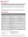
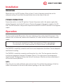
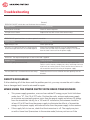
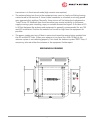
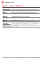
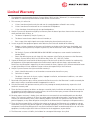
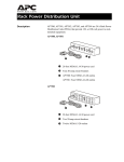
INSTALLATION &
OPERATION MANUAL
PWS120 & PWS 240
Power Supplies
An ISO9001 and AS9100 Registered Company Battery Chargers • Inverters • Power Supplies • Voltage Converters
8128 River Way, Delta B.C. V4G 1K5 Canada T. 604.946.9981 F. 604.946.9983 TF. 800.668.3884 (US/CANADA)
www.analyticsystems.com
Copyright (2005-2014) Analytic Systems Ware (1993) Ltd.
IMPORTANT & SAFETY INSTRUCTIONS
SAVE THESE INSTRUCTIONS — This manual contains important safety and operating instructions for the converter.
ALL POWER SUPPLIES
1. WARNING – Unless the label specifically states that the power supply may be used for
battery charging, it must NOT be used for that purpose.
2. Do not expose power supply to rain or snow.
3. Use of an attachment not recommended or sold by the power supply manufacturer may
result in a risk of fire, electric shock, or injury to persons.
4. Do not disassemble power supply; take it to a qualified serviceman when service or
repair is required. Incorrect reassembly may result in a risk of electric shock or fire.
5. To reduce risk of electric shock, disconnect power supply from AC supply before attempting any maintenance or cleaning. Turning off controls will not reduce this risk.
6. DC CONNECTION PRECAUTIONS
i.
Connect and disconnect DC output connections only after setting power supply
switch to off position.
DANGER — Never alter the AC cord or plug provided. If it will not fit the outlet, have the
proper cord installed by a qualified electrician. Improper connection can result in a risk of an
electric shock. Your power supply should be grounded to reduce the risk of electric shock. The
power supply is equipped with a grounding conductor and a grounding plug.
Analytic Systems does not recommend the use of the PWS120 Series Power Supplies in life
support applications where failure or malfunction of this product can be reasonably expected
to cause failure of the life support device or to significantly affect its safety or effectiveness.
Analytic Systems does not recommend the use of any of its products in direct patient care.
Examples of devices considered to be life support devices are neonatal oxygen analyzers,
nerve stimulators (whether used for anesthesia, pain relief, or other purposes), autotransfusion devices, blood pumps, defibrillators, arrhythmia detectors and alarms, pacemakers,
hemodialysis systems, peritoneal dialysis systems, neonatal ventilator incubators, ventilators
for both adults and infants, anesthesia ventilators, and infusion pumps as well as any other
devices designated as “critical” by the U.S. FDA.
3
Introduction
The PWS120 & PWS240 Power Supplies are MosFet based switchmode power supplies
designed for high reliability, high efficiency and minimum size. Circuit innovations reduce
output ripple to levels previously available only from bulky, inefficient linear power supplies.
Current limiting and safe operating area circuitry protect the transistors. A crowbar circuit
protects any devices powered by the unit from excessive voltage in the unlikely event of a
failure.
Applications include running 12Vdc equipment from 120Vac power including VHF radios, CB
radios, sound equipment, GPS receivers, plotters, 12 Volt lighting systems and automotive &
marine electronics displays.
Specifications
General
Input Voltage (Vac)
100 - 130
Input Isolation
> 1500 VDC
200 - 260
Input Fuse (PWS120)
3 Amp AGC (120Vac)
2 Amp AGC (250Vac)
Input Fuse (PWS240)
6.3 Amp AGC (120Vac)
4 Amp AGC (250Vac)
Output Voltage (Vdc)
13.8 ± 0.1
Output Current (Amps)
10 Cont. / 14 Peak (PWS120)
23 Cont. / 25 Peak (PWS240)
Current Limit
16 Amps (PWS120)
27 Amps (PWS240)
Output Ripple (milliVolts)
< 10 @ full load (PWS120)
< 15 @ full load (PWS240)
Transient Response
< 2V for 5A Surge
Efficiency
> 80% @ 12 Amps Out
Temp. Rise
< 40 deg C @ 14 Amps Out
Length
7.5 in / 19.1 cm
Width
8.7 in / 21.8 cm
Height
2.4 in / 5.6 cm
Clearance
1 Inch (2.5 cm) all around
Material
Marine Grade Aluminium
Finish
Black Anodize / Black Powder Epoxy
Weight
3.0 lb / 1.4 kg (PWS120)
3.5 lb / 1.6 kg (PWS240)
* Specifications subjects to change without notice.
Designed and manufactured by: ANALYTIC SYSTEMS WARE (1993) LTD.
8128 River Way
Delta, BC V4G 1K5 Canada
p. 604.946.9981 f. 604.946.9983 tf. 800.668.3884 US/Canada
www.analyticsystems.com
[email protected] Revised November 2014
4
Installation
MOUNTING
Mount the unit in a DRY location. Allow at least 1 inch of clearance around the unit for
adequate cooling. Do not block the ventilation slots on the sides of the unit.
POWER CONNECTION
Ensure the switch is in the OFF position. Connect the power cord to the power supply then
connect the power cord to the AC source. Connect the output of the power supply to the DC
load. The RED terminal is the positive output and the BLACK or WHITE terminal is the negative
output.
Operation
Turn the switch to the ON position. The neon indicator in the switch should illuminate. If the
indicator fails to illuminate, recheck the connection, AC outlet and the fuse inside the power
supply.
This unit may be converted from 110Vac input operation to 220Vac input operation.
For instructions on this conversion please call Analytic Systems at 800-668-3884.
The PWS120 is cooled by convection and has no over temperature shutdown. Ensure adequate
ventilation for cooling.
The PWS240 is cooled by convection and forced air (via a fan). The fan operates when the
transformer temperature exceeds 70 degrees Celsius. If for some reason the temperature
should exceed 100 degrees Celsius the unit will shut down. After the unit has cooled down it
will resume normal operation.
NOTE:
Place the unit in a well ventilated, open and cool area. Do not block the openings of the fan
intake at the bottom of the unit or the exhaust openings at the side of the unit!
5
Troubleshooting
(General)
PROBLEM: ON/OFF switch does not illuminate when turned on.
Probable Cause
Suggested Remedy
No AC power available.
Check AC outlet for power.
AC input fuse is blown.
Replace the fuse with a fuse of the correct rating.
PROBLEM: AC input fuse blows as soon as power is turned on
Probable Cause
Suggested Remedy
Input voltage is low
Check input voltage
The unit is in current limit due to a large reactive
load or the output terminals are shorted together
Check that the output terminals are not shorted together.
Remove the load and check the output voltage. If it is normal,
then the load is too much for the power supply.
PROBLEM: The output voltage drops as soon as the load is applied.
Probable Cause
Suggested Remedy
The unit is going into current limit.
Reduce the load current to less than the rated current limit.
Devices such as motors, compressors, relays and lamps can have
high inrush or starting currents. Please ensure these currents do
not exceed the current limit rating of the power supply.
The unit (PWS240) is shut down due to over temp
Check that the fan has not failed or the vent openings are not
blocked.
DEFECTS OR DAMAGE
If after checking all of the above and the problem persists, you may assume the unit is defective or damaged and it must be returned for repair.
WHEN USING THE POWER SUPPLY WITH RADIO TRANSCEIVERS
• This power supply generates, uses and can radiate RF energy as per limits laid down
under class “B”, Part 15 of FCC rules. Position the radio, antenna and power supply
to minimize any received spurious noise from the power supply and excess RF energy
from the transmitter. Ideally, for a 100 watt HF installation, the antenna should be
at least 40 to 50 feet from the power supply to eliminate the effects of transmitter
energy on the power supply and induced noise from the power supply to the receiver.
• If the supply fails to turn on, check that the transceiver is off. The supply may turn
on with a lower load (transceiver in the receive mode) but may not turn on if the
6
transceiver is in the transmit mode (high current consumption).
• The antenna being too close to the equipment may cause a slowly oscillating buzzing
carrier heard in the receiver. A loose coaxial connector or a broken or missing ground
may aggravate this problem. Normally, these noises will be below the background or
“band” noise. RF feedback from the transmitter may create instability in the power
supply causing a poor sounding, raspy or unstable transmitted signal. A distance of 40
to 50 feet between the antenna and equipment is generally recommended for any 100
watt HF installation. Position the antenna as far and as high from the equipment as
possible.
• The power supply may turn off due to excessive transmitter energy being coupled into
the AC and the DC lines. Either your antenna is too close (less than 10 feet) or the
antenna system is not radiating properly. First check the antenna system SWR. Then, if
necessary, relocate either the antenna or the equipment further apart.
MECHANICAL DRAWING
7
Intentional blank page
8
Intentional blank page
9
Special Services & Options
Conformal Coating
INCLUDED ON ALL UNITS UNLESS REQUESTED NOT TO as of April 1, 2014
Option “c”
Ruggedization Package (EXTRA Conformal Coating and RTV Compound)
Option “v”
Marine / Industrial Pkg (EXTRA Conformal dipping and RTV Compound)
Option “MS”
Military Pkg
(incl. Wide Temp Components, Conformal Dipping and RTV Compound)
Option “w”
Wide Temperature Operation (-40 to +55 C, incl)
Option “SM”
High Voltage Protection on the DC Input Side
Option “d”
Paralleling Diodes
Option “FI”
Forklift Modifications
Option “F”
Open Frame - No chassis just heat sink bars (not for all products)
Special Input
Special Output
There is no charge for nominal output voltages (ie. 12.0, 24.0, 48.0), but this
must be noted at the time of order (Contact Factory for details)
Water tight options
IP66, IPS67, IPS68
10
Limited Warranty
1. The equipment manufactured by Analytic Systems Ware (1993) Ltd. (the “Warrantor”) is warranted to be free
from defects in workmanship and materials under normal use and service.
2. This warranty is in effect for:
a. 3 Years from date of purchase by the end user for standard products offered in our catalog.
b. 2 Years from date of manufacture for non-standard or OEM products
c.
1 Year from date of manufacture for encapsulated products.
3. Analytic Systems will determine eligibility for warranty from the date of purchase shown on the warranty card
when returned within 30 days, or
a. The date of shipment by Analytic Systems, or
b. The date of manufacture coded in the serial number, or
c.
From a copy of the original purchase receipt showing the date of purchase by the user.
4. In case any part of the equipment proves to be defective, the Purchaser should do the following:
a. Prepare a written statement of the nature of the defect to the best of the Purchasers knowledge, and
include the date of purchase, the place of purchase, and the Purchasers name, address and telephone
number.
b. Call Analytic Systems at 800-668-3884 or 604-946-9981 and request a return material authorization
number (RMA).
c.
Return the defective part or unit along with the statement at the Purchasers expense to the Warrantor;
Analytic Systems Ware (1993) Ltd., 8128 River Way, Delta, B.C., V4G 1K5, Canada.
5. If upon the Warrantor’s examination the defect proves to be the result of defective material or workmanship,
the equipment will be repaired or replaced at the Warrantor’s option without charge, and returned to the
Purchaser at the Warrantor’s expense by the most economical means. Requests for a different method of return
or special handling will incur additional charges and are the responsibility of the Purchaser.
6. Analytic Systems reserves the right to void the warranty if:
a. Labels, identification marks or serial numbers are removed or altered in any way.
b. Our invoice is unpaid.
c.
The defect is the result of misuse, neglect, improper installation, environmental conditions, non-authorized repair, alteration or accident.
7. No refund of the purchase price will be granted to the Purchaser, unless the Warrantor is unable to remedy the
defect after having a reasonable number of opportunities to do so.
8. Only the Warrantor shall perform warranty service. Any attempt to remedy the defect by anyone else shall
render this warranty void.
9. There shall be no warranty for defects or damages caused by faulty installation or hook-up, abuse or misuse of
the equipment including exposure to excessive heat, salt or fresh water spray, or water immersion except for
equipment specifically stated to be waterproof.
10.No other express warranty is hereby given and there are no warranties that extend beyond those described
herein. This warranty is expressly in lieu of any other expressed or implied warranties, including any implied
warranty of merchantability, fitness for the ordinary purposes for which such goods are used, or fitness for a
particular purpose, or any other obligations on the part of the Warrantor or its employees and representatives.
11.There shall be no responsibility or liability whatsoever on the part of the Warrantor or its employees and representatives for injury to any person or persons, or damage to property, or loss of income or profit, or any other
consequential or resulting damage which may be claimed to have been incurred through the use or sale of the
equipment, including any possible failure of malfunction of the equipment, or part thereof.
12.The Warrantor assumes no liability for incidental or consequential damages of any kind
11
An ISO9001 and AS9100 Registered Company Battery Chargers • Inverters • Power Supplies • Voltage Converters
8128 River Way, Delta B.C. V4G 1K5 Canada T. 604.946.9981 F. 604.946.9983 TF. 800.668.3884 (US/CANADA)
www.analyticsystems.com