1
QNAP Turbo NAS
User Manual
(Version: 3.3.0)
© 2010 QNAP Systems, Inc. All Rights Reserved.
Table of Contents
1. Notice.............................................................................................................6
.......................................................................................................
7
1.1 Regulatory
Notice
8
1.2 Symbols.......................................................................................................
in this document
9
1.3 Safety .......................................................................................................
Information and Precautions
.............................................................................................................10
2. Getting
Started
.......................................................................................................
15
2.1 Browse
the CD-ROM
.......................................................................................................
17
2.2 Hard Disk
Drive Compatibility List
18
2.3 Check.......................................................................................................
System Status (LED and Alarm Buzzer)
.......................................................................................................
21
2.4 Connect
to the NAS Network Shares
.......................................................................................................
23
2.5 Connect
to the NAS by Web Browser
.......................................................................................................
29
2.6 System
Migration
.............................................................................................................32
3. System
Administration
.......................................................................................................
33
3.1 General
Settings
....................................................................................................... 37
3.2 Network
....................................................................................................... 48
3.3 Hardware
....................................................................................................... 51
3.4 Security
....................................................................................................... 54
3.5 Notification
57
3.6 Power.......................................................................................................
Management
.......................................................................................................
59
3.7 Network
Recycle Bin
.......................................................................................................
60
3.8 Backup/
Restore Settings
.......................................................................................................
61
3.9 System
Logs
.......................................................................................................
64
3.10 Firmware
Update
.......................................................................................................
69
3.11 Restore
to Factory Default
4. Disk.............................................................................................................70
Management
.......................................................................................................
70
4.1 Volume
Management
....................................................................................................... 74
4.2 RAID Management
2
....................................................................................................... 96
4.3 HDD SMART
.......................................................................................................
97
4.4 Encrypted
File System
4.5 iSCSI ....................................................................................................... 98
.......................................................................................................
135
4.6 Virtual
Disk
.............................................................................................................137
5. Access
Right Management
5.1 Users....................................................................................................... 137
143
5.2 User .......................................................................................................
Groups
.......................................................................................................
144
5.3 Share
Folders
....................................................................................................... 161
5.4 Quota
.............................................................................................................162
6. Network
Services
.......................................................................................................
163
6.1 Microsoft
Networking
176
6.2 Apple.......................................................................................................
Networking
177
6.3 NFS .......................................................................................................
Service
....................................................................................................... 180
6.4 FTP Service
.......................................................................................................
182
6.5 Telnet/
SSH
.......................................................................................................
183
6.6 SNMP
Settings
185
6.7 Web .......................................................................................................
Server
6.7.1 Virtual
.....................................................................................................
Host
208
.......................................................................................................
212
6.8 Network Service Discovery
.............................................................................................................214
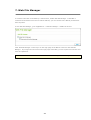
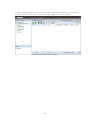
7. Web
File Manager
.............................................................................................................222
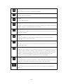
8. Multimedia
Station
....................................................................................................... 255
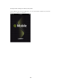
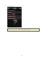
8.1 QMobile
.............................................................................................................282
9. Download
Station
.............................................................................................................294
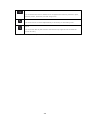
10. Surveillance
Station
.............................................................................................................302
11. iTunes
Service
.............................................................................................................305
12. UPnP
Media Server
.............................................................................................................307
13. MySQL
Server
.............................................................................................................309
14. QPKG
Plugins
3
.............................................................................................................311
15. Backup
.......................................................................................................
311
15.1 External
Drive
313
15.2 USB.......................................................................................................
One Touch Copy
.......................................................................................................
316
15.3 Remote
Replication
.......................................................................................................
327
15.4 Time
Machine
.............................................................................................................332
16. External
Device
.......................................................................................................
332
16.1 External
Storage Device
333
16.2 USB.......................................................................................................
Printer
16.2.1.....................................................................................................
Windows XP Users
334
16.2.2.....................................................................................................
Windows Vista/ Windows 7 Users
336
16.2.3.....................................................................................................
Mac OS X 10.4
338
16.2.4.....................................................................................................
Mac OS X 10.5
343
349
16.3 UPS.......................................................................................................
Settings
.............................................................................................................354
17. System
Status
.......................................................................................................
354
17.1 System
Information
.......................................................................................................
355
17.2 System
Service
.......................................................................................................
356
17.3 Resource
Monitor
.............................................................................................................359
18. Use
the LCD Panel
.............................................................................................................366
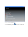
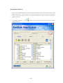
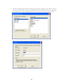
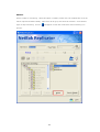
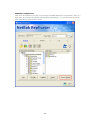
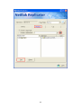
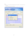
19. NetBak
Replicator
.............................................................................................................383
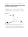
20. Connect
to QNAP NAS from the Internet (DDNS Service)
.............................................................................................................391
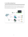
21. Set
SMS and Email Alert
.............................................................................................................400
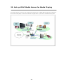
22. Set
up UPnP Media Server for Media Playing
.............................................................................................................409
23. Host
a Forum with phpBB on QNAP NAS
.............................................................................................................421
24. NAS
Maintenance Settings
.......................................................................................................
422
24.1 Restart/
Shut down Server
.......................................................................................................
424
24.2 Reset
Administrator Password and Network Settings
.......................................................................................................
426
24.3 System
Temperature Protection
.......................................................................................................
427
24.4 Troubleshooting-Abnormal
RAID Operation
4
.............................................................................................................429
25. GNU
GENERAL PUBLIC LICENSE
5
1. Notice
Thank you for choosing QNAP products! This user manual provides detailed instructions of using the
Turbo NAS (network-attached storage). Please read carefully and start to enjoy the powerful
functions of the Turbo NAS!
The Turbo NAS is hereafter referred to as the NAS.
This manual provides the description of all the functions of the Turbo NAS. The product you
purchased may not support certain functions dedicated to specific models.
Le g a l No tic e s
©C opyright 2009–2010. QNAP Systems, Inc. All Rights Reserved.
All the features, functionality, and other product specifications are subject to change without prior
notice or obligation. Information contained herein is subject to change without notice.
QNAP and the QNAP logo are trademarks of QNAP Systems, Inc. All other brands and product
names referred to are trademarks of their respective holders.
Further, the ® or ™ symbols are not used in the text.
DIS CLA IME R
In no event shall the liability of QNAP Systems, Inc. (QNAP) exceed the price paid for the product
from direct, indirect, special, incidental, or consequential software, or its documentation. QNAP
makes no warranty or representation, expressed, implied, or statutory, with respect to its products
or the contents or use of this documentation and all accompanying software, and specifically
disclaims its quality, performance, merchantability, or fitness for any particular purpose. QNAP
reserves the right to revise or update its products, software, or documentation without obligation to
notify any individual or entity.
Back up your system periodically to avoid any potential data loss. QNAP disclaims any responsibility
of all sorts of data loss or recovery.
Should you return any components of the NAS package for refund or maintenance, make sure they
are carefully packed for shipping. Any form of damages due to improper packaging will not be
compensated.
6
1.1 Regulatory Notice
F CC S T A T E ME NT
This equipment has been tested and found to comply with the limits for a C lass B digital device,
pursuant to Part 15 of FC C Rules. These limits are designed to provide reasonable protection
against harmful interference in a residential installation. This equipment generates, uses, and can
radiate radio frequency energy and, if not installed and used in accordance with the instructions,
may cause harmful interference to radio communications. However, there is no guarantee that
interference will not occur in particular installation. If this equipment does cause harmful
interference to radio or television reception, which can be determined by turning the equipment off
and on, the user is encouraged to try to correct the interference by one or more of the following
measures:
Reorient or relocate the receiving antenna.
Increase the separation between the equipment and receiver.
C onnect the equipment into an outlet on a circuit different from that to which the receiver is
connected.
C onsult the dealer or an experienced radio/television technician for help.
The changes or modifications not expressly approved by the party responsible for compliance could
void the user’s authority to operate the equipment.
Shielded interface cables, if any, must be used in order to comply with the emission limits.
CE NOT ICE
C lass B only.
7
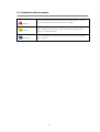
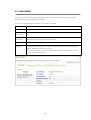
1.2 Symbols in this document
This icon indicates the instructions must be strictly followed. Failure to
Warning
do so could result in injury to human body or death.
This icon indicates the action may lead to disk clearance or loss OR
C aution
failure to follow the instructions could result in data damage, disk
damage, or product damage.
This icon indicates the information provided is important or related to
Important
legal regulations.
8
1.3 Safety Information and Precautions
1.
The NAS can operate normally in the temperature of 0ºC –40ºC and relative humidity of 0%–
95%. Please make sure the environment is well-ventilated.
2.
The power cord and devices connected to the NAS must provide correct supply voltage
(100W, 90–264V).
3.
Do not place the NAS in direct sunlight or near chemicals. Make sure the temperature and
humidity of the environment are in optimized level.
4.
Unplug the power cord and all the connected cables before cleaning. Wipe the NAS with a dry
towel. Do not use chemical or aerosol to clean the NAS.
5.
Do not place any objects on the NAS for the server’s normal operation and to avoid overheat.
6.
Use the flat head screws in the product package to lock the hard disk drives (HDD) in the NAS
when installing the HDD for proper operation.
7.
Do not place the NAS near any liquid.
8.
Do not place the NAS on any uneven surface to avoid falling off and damage.
9.
Make sure the voltage is correct in your location when using the NAS. If you are not sure,
please contact the distributor or the local power supply company.
10. Do not place any object on the power cord.
11. Do not attempt to repair your NAS in any occasions. Improper disassembly of the product
may expose you to electric shock or other risks. For any enquiries, please contact the
distributor.
12. The chassis (also known as rack mount) NAS models should only be installed in the server
room and maintained by the authorized server manager or IT administrator. The server
room is locked by key or keycard access and only certified staff is allowed to enter the server
room.
W a r n in g :
Danger of explosion if battery is incorrectly replaced. Replace only with the same or
equivalent type recommended by the manufacturer. Dispose of used batteries according to
the manufacturer’s instructions.
Do NOT touch the fan inside the system to avoid serious injuries.
9
2. Getting Started
Hardware Installation
For the information of hardware installation, see the ‘Quick Installation Guide’ (QIG) in the product
package. You can also find the QIG in the product C D-ROM or QNAP website (http://www.qnap.com/
).
Software Installation
After you have installed the NAS hardware, you can proceed to the software installation. The
following demonstration is based on Windows OS.
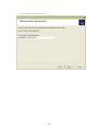
1. Install QNAP Finder from the product C D-ROM.
10
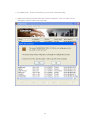
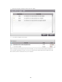
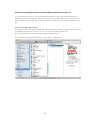
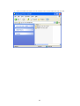
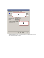
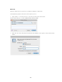
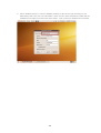
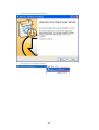
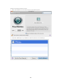
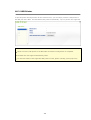
2. Run QNAP Finder. If Finder is blocked by your firewall, unblock the utility.
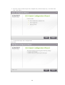
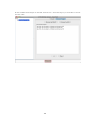
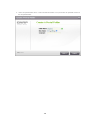
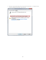
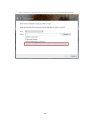
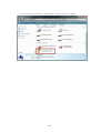
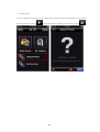
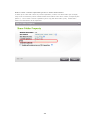
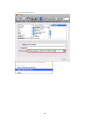
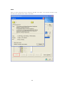
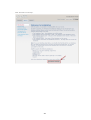
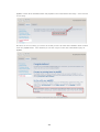
3. QNAP Finder detects your NAS which has not been configured. C lick 'Yes' which you are
prompted to perform quick setup of the NAS.
11
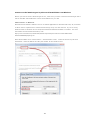
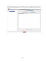
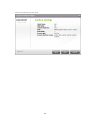
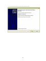
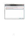
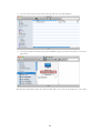
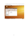
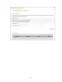
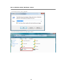
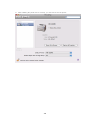
4. C lick 'OK' to proceed.
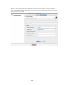
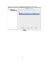
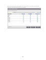
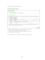
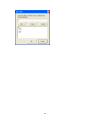
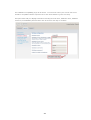
5. Your default web browser will be opened. Follow the instructions to configure the NAS.
12
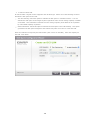
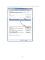
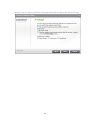
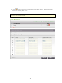
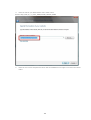
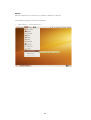
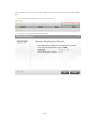
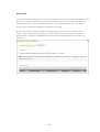
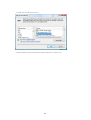
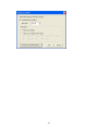
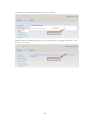
6. C lick 'START INSTALLATION' in the last step.
7. All the installed hard disk drives will be formatted and all the data will be cleared. C lick 'OK' to
proceed.
13
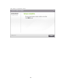
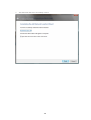
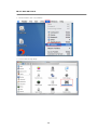
8. When finished, click 'Return to system administration page' or enter the NAS IP in the web
browser to connect to the web administration page of the NAS.
14
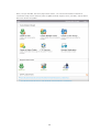
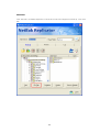
2.1 Browse the CD-ROM
The NAS C D-ROM contains documentation including Quick Installation Guide (QIG), user manual,
application notes, and software utilities QNAP Finder, NetBak Replicator, and QGet.
15
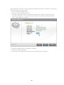
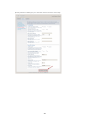
You can browse the C D-ROM and access the following contents:
Finder: The setup program of QNAP Finder (for Windows OS).
Firmware: The firmware IMG file for the NAS model you purchased.
Mac: The setup program of QNAP Finder (for Mac OS).
Manual: The Quick Installation Guide, software user manuals, and hardware manual of Turbo
NAS.
QGet: The setup program of QGet download utility (for Windows OS).
QSG: View the hardware installation instructions of the NAS.
Replicator: The setup program of NetBak Replicator (Windows utility for data backup from
Windows OS to QNAP NAS).
The above contents are also available on QNAP website (http://www.qnap.com/).
16
2.2 Hard Disk Drive Compatibility List
This product works with 2.5-inch/ 3.5-inch SATA hard disk drives (HDD) from major HDD brands.
For the HDD compatibility list, please visit http://www.qnap.com/.
Im p o r ta n t: QNAP disclaims any responsibility for product damage/ malfunction or data
loss/ recovery due to misuse or improper installation of hard disks in any occasions for any
reasons.
Ca u tio n : Note that if you install a HDD (new or used) which has never been installed on
the NAS before, the HDD will be formatted and partitioned automatically and all the disk
data will be cleared.
17
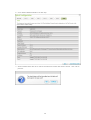
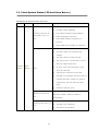
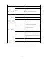
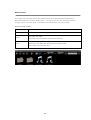
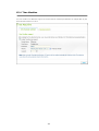
2.3 Check System Status (LED and Alarm Buzzer)
LE D Dis p la y & S y s te m S ta tu s Ov e r v ie w
LE D
Co lo u r
LE D S ta tu s
De s c r ip tio n
1)
The HDD on the NAS is being formatted
2)
The NAS is being initialised
Flashes green and red
3)
The system firmware is being updated
alternately every 0.5
4)
RAID rebuilding is in process
sec
5)
Online RAID capacity expansion is in
process
6)
Online RAID level migration is in process
1)
The HDD is invalid
2)
The disk volume has reached its full
capacity
3)
The disk volume is going to be full
4)
The system fan is out of function (TS-119
does not support smart fan.)
System
Re d /
Status
Gre e n
5)
An error occurs when accessing (read/
Red
write) the disk data
6)
A bad sector is detected on the HDD
7)
The NAS is in degraded read-only mode (2
member HDD fail in a RAID 5 or RAID 6
configuration, the disk data can still be
read)
8)
(Hardware self-test error)
The NAS is in degraded mode (one member
Flashes red every 0.5
HDD fails in RAID 1, RAID 5 or RAID 6
sec
configuration)
1)
The NAS is starting up
2)
The NAS is not configured
3)
The HDD is not formatted
Flashes green every 0.5
sec
18
LE D
Co lo u r
LE D S ta tu s
De s c r ip tio n
Green
The NAS is ready
Off
All the HDD on the NAS are in standby mode
The disk data is being accessed and a read/
Orange
LAN
write error occurs during the process
Or a n g e
Flashes orange
The NAS is connected to the network
Flashes red
The NAS is being accessed from the network
Re d /
Red
A HDD read/ write error occurs
Gre e n
Flashes green
The disk data is being accessed
Green
The HDD can be accessed
HDD
1)
A USB device (connected to front USB port)
is being detected
2)
is being removed from the NAS
Flashes blue every 0.5
3)
sec
A USB device (connected to front USB port)
The USB device (connected to the front USB
port) is being accessed
4)
USB
Blu e
The data is being copied to or from the
external USB or eSATA device
1)
A front USB device is detected (after the
device is mounted)
2)
Blue
The NAS has finished copying the data to or
from the USB device connected to the front
USB port
eSATA*
Off
No USB device can be detected
Flashes
The eSATA device is being accessed
Off
No eSATA device can be detected
Or a n g e
* TS-210, TS-219, TS-439U-SP/RP, TS-809 Pro, TS-809U-RP do not support eSATA port.
19
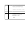
A la r m Bu z z e r (th e a la r m b u z z e r c a n b e d is a b le d in ‘S y s te m T o o ls ’ > ‘Ha r d wa r e S e ttin g s ’)
Be e p s o u n d
No . o f T im e s
Short beep (0.5
1
sec)
Short beep (0.5
3
sec)
Short beep (0.5
De s c r ip tio n
1)
The NAS is starting up
2)
The NAS is being shut down (software shutdown)
3)
The user presses the reset button to reset the NAS
4)
The system firmware has been updated
The NAS data cannot be copied to the external storage device
from the front USB port
3, every 5 min
sec), long beep
The system fan is out of function (TS-119 does not support
smart fan.)
(1.5 sec)
Long beep (1.5
2
sec)
1
1)
The disk volume is going to be full
2)
The disk volume has reached its full capacity
3)
The HDD on the NAS are in degraded mode
4)
The user starts HDD rebuilding
1)
The NAS is turned off by force shutdown (hardware
shutdown)
2)
The NAS has been turned on and is ready
20
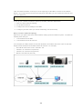
2.4 Connect to the NAS Network Shares
Windows Users
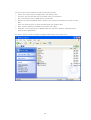
1. You can connect to the network shares of the NAS by the following means:
a.
Open My Network Places and find the workgroup of the NAS. If you cannot find the server,
browse the whole network to search for the NAS. Double click the name of the NAS for
connection.
b.
Use the Run function in Windows. Enter \\NAS name or \\NAS IP
21
2.
Enter the default administrator name and password.
Default user name: admin
Default password: admin
3.
You can upload files to the network shares.
Mac Users
1. C hoose 'Go' > 'C onnect to Server'.
2. There are two ways to mount a disk:
AFP: type NAS IP or afp://NAS_IP
SMB: type smb://NAS_IP or NAS_name
For example, 169.254.100.100 or smb://169.254.100.100
3. C lick 'C onnect'.
Linux Users
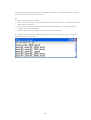
On Linux, run the following command:
m o u n t - t n fs <NA S IP>:/ <Ne two r k S h a r e Na m e > <Dir e c to r y to Mo u n t>
For example, if the IP address of your NAS is 192.168.0.1 and you want to link the network share
folder ‘public’ under the /mnt/pub directory, use the following command:
m o u n t - t n fs 1 9 2 .1 6 8 .0 .1 :/ p u b lic / m n t/ p u b
No te : You must login as the ‘root’ user to initiate the above command.
Login as the user ID you define, you can use the mounted directory to connect to your shared files.
22
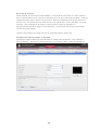
2.5 Connect to the NAS by Web Browser
Co n n e c t to th e NA S b y we b b r o ws e r o n W in d o ws o r Ma c OS
1. You can connect to the web administration page of the NAS by the following methods:
a. Use Finder to find the NAS.
b. Open a web browser and enter http://NAS IP:8080
No te : The default NAS IP is 169.254.100.100:8080. If you have configured the NAS to use
DHC P, you can use Finder to check the IP address of the NAS. Make sure the NAS and the
computer that runs Finder are connected to the same subnet. If you cannot search for the
NAS IP, connect the NAS to your computer directly and run Finder again.
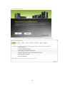
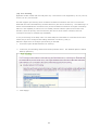
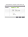
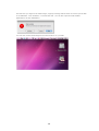
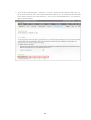
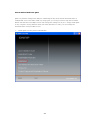
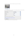
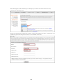
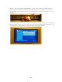
2. C hoose the display language from the drop-down menu on the login page of the NAS or after
you login the NAS.
23
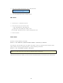
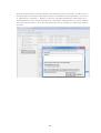
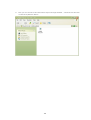
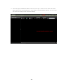
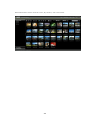
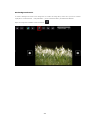
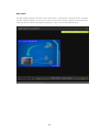
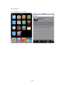
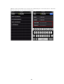
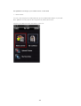
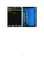
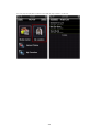
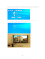
3. You can select to browse the NAS UI with Standard view or Flow view.
S ta n d a r d v ie w
F lo w v ie w
24
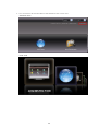
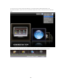
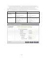
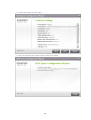
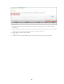
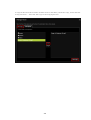
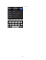
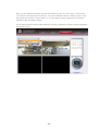
4. To configure the NAS, click ‘ADMINISTRATION’. Enter the administrator name and password.
Default user name: admin
Default password: admin
Note that if you login the administration interface with a user account without the administration
right, you can only change your login password.
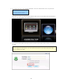
5. You can turn on the option ‘SSL login’ (Secure Sockets Layer login) to allow secure connection to
the NAS.
No te : If your NAS is placed behind an NAT gateway and you want to access the NAS by
secure login from the Internet, you must open the port 443 on your NAT and forward this
port to LAN IP of the NAS.
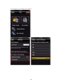
25
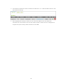
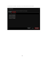
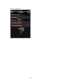
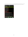
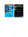
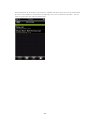
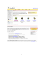
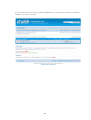
After you login the NAS, the home page will be shown. You can find the software wizards for
convenient setup of some features, links to QNAP technical support, forum, and Wiki, and the latest
RSS news feeds from QNAP*.
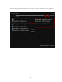
26
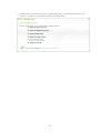
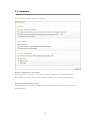
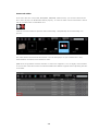
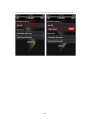
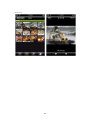
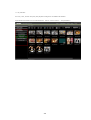
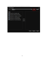
There are 8 main sections in the server administration.
C lick the triangle icon next to the section name to expand the tree and view the items listed under
each section.
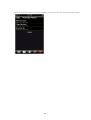
27
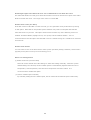
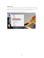
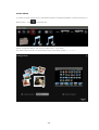
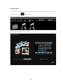
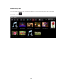
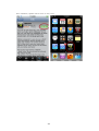
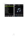
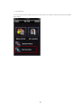
To use the services such as Web File Manager, Download Station, Multimedia Station, and
Surveillance Station, choose the services from the drop-down menu or click the icons on the login
page.
After you login the NAS, you can click the icons on top of the page to access the services.
28
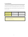
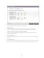
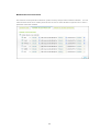
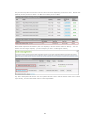
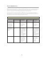
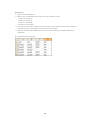
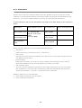
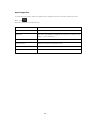
2.6 System Migration
System migration allows existing QNAP NAS users to upgrade your NAS to another new QNAP NAS
model without the need to transfer the data or reconfigure the system. You only need to install the
original hard disk drives (HDD) on the new NAS following its original HDD order and restart the NAS.
Due to different hardware design, the NAS will automatically check if a firmware update is required
before system migration. After the migration has finished, all the settings and data will be kept and
applied to the new NAS.
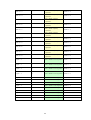
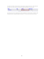
The following table shows the NAS models which support system migration.
S o u r c e NA S
De s tin a tio n NA S
Re m a r k s
TS-x10/ TS-x19/ TS-x39/ 509/
TS-x10/ TS-x19/ TS-x39/ 509/
Firmware update required.
809/ SS-x39/ TS-x59
809/ SS-x39
TS-x10/ TS-x19/ TS-x39/ 509/
TS-x59
Firmware update not required.
809/ SS-x39/ TS-x59
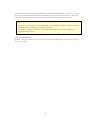
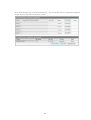
No te :
The destination should contain enough drive bays to house the number of hard disk drives in
the disk volume of the source NAS.
SS-x39 series supports only 2.5-inch HDD.
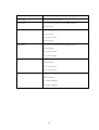
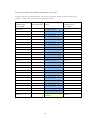
29
De s tin a tio n NA S
Dis k v o lu m e s u p p o r te d fo r s y s te m m ig r a tio n
1-bay NAS
1-drive single disk volume
2-bay NAS
1 to 2-drive single disk volume/ JBOD/ RAID 0,
2-drive RAID 1.
4-bay NAS
1 to 4-drive single disk volume/ JBOD/ RAID 0,
2-drive RAID 1,
3 to 4-drive RAID 5,
4-drive RAID 6.
5-bay NAS
1 to 5-drive single disk volume/ JBOD/ RAID 0,
2-drive RAID 1,
3 to 5-drive RAID 5,
4 to 5-drive RAID 6.
6-bay NAS
1 to 6-drive single disk volume/ JBOD/ RAID 0,
2-drive RAID 1,
3 to 6-drive RAID 5,
4 to 6-drive RAID 6.
8-bay NAS
1 to 8-drive single disk volume/ JBOD/ RAID 0,
2-drive RAID 1,
3 to 8-drive RAID 5,
4 to 8-drive RAID 6.
30
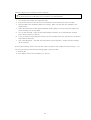
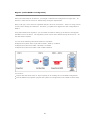
Follow the steps below to perform system migration.
Ca u tio n : To avoid server damage or serious injuries, the system migration procedure should
be performed by an authorized server manager or IT administrator.
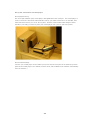
1.
Turn off the source NAS and unplug the HDD.
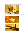
2.
Remove the HDD from the old trays and install them to the HDD trays of the new NAS.
3.
Plug the HDD to the destination NAS (new model). Make sure the HDD are installed in the
original order.
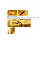
4.
Follow the instructions of the Quick Installation Guide (QIG) to connect the power supply and
network cable(s) of the new NAS.
5.
Turn on the new NAS. Login the web administration interface as an administrator (default
login: admin; password: admin).
6.
If you are informed to update the firmware of the new NAS, follow the instructions to download
and install the firmware.
7.
C lick 'Start Migrating'. The NAS will restart after system migration. All the data and settings
will be retained.
Some system settings will be removed after system migration due to different system design. You
may need to configure the following settings again on the new NAS.
Windows AD
Some QPKGs need to be resintalled (e.g. XDove)
31
3. System Administration
You can configure general system settings, network settings, and hardware settings, update the
firmware, and more in this section.
General Settings 33
Network 37
Hardware 48
Security 51
Notification 54
Power Management 57
Network Recycle Bin 59
Backup/ Restore Settings 60
System Logs 61
Firmware Update 64
Restore to Factory Default 69
32
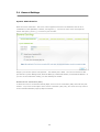
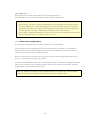
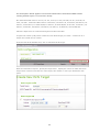
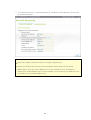
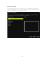
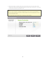
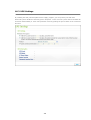
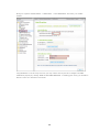
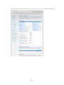
3.1 General Settings
Sy ste m Adm inistra tion
Enter the name of the NAS. The server name supports maximum 14 characters and can be a
combination of the alphabets, numbers, and hyphen (-). The server name does not accept the
names with space, period (.), or names in pure number.
Assign a port for the system management. The default port is 8080. The services which use this
port include: System Management, Web File Manager, Multimedia Station, and Download Station. If
you are not sure about this setting, use the default port number.
E n a b le S e c u r e Co n n e c tio n (S S L)
To allow the users to connect the NAS by https, turn on secure connection (SSL) and enter the port
number. If you turn on the option ‘Force secure connection (SSL) only’, the users can only connect
to the web administration page by https connection.
33
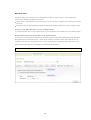
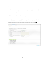
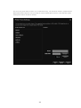
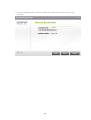
Da te a nd Tim e
Adjust the date, time, and time zone of the NAS according to your location. If the settings are
incorrect, the following problems may occur:
When using a web browser to access the server or save a file, the display time of the action will be
incorrect.
The time of the event log displayed will be inconsistent with the actual time when an action occurs.
S e t th e s e r v e r tim e th e s a m e a s y o u r c o m p u te r tim e
To synchronize the server time with the time of your computer, click 'Update now' next to this option.
S y n c h r o n iz e with a n In te r n e t tim e s e r v e r a u to m a tic a lly
You can turn on this option to synchronize the date and time of the NAS automatically with specified
NTP (Network Time Protocol) server. Enter the IP address or domain name of the NTP server, for
example, time.nist.gov, time.windows.com. Then enter the time interval for synchronization. This
option can be used only when the NAS is connected to the Internet.
No te : The first time synchronization may take several minutes to complete.
34
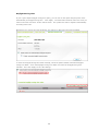
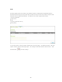
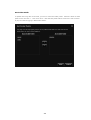
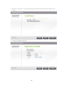
Da y light Sa v ing Tim e
If your region adopts daylight saving time (DST), you can turn on the option ‘Adjust system clock
automatically for daylight saving time’. C lick ‘Apply’. The latest DST schedule of the time zone you
select in the ‘Date and Time’ section will be shown. The system time will be adjusted automatically
according to the DST.
Note that if your region does not adopt DST, the options on this page will not be available.
To enter the daylight saving time table manually, select the option ‘Enable customized daylight
saving time table’. C lick ‘Add Daylight Saving Time Data’ and enter the daylight saving time
schedule. Then click ‘Apply’ to save the settings.
35
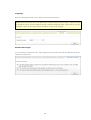
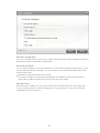
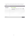
La ngua ge
Select the language the NAS uses to display the files and directories.
No te : All files and directories on the NAS will be created using Unicode encoding. If the FTP clients
or the OS of your PC does not support Unicode, select the language which is the same as your OS
language in order to view the files and directories on the server properly.
Pa ssword Stre ngth
You can specify the password rules. After applying the setting, the NAS will automatically check the
validity of the password.
36
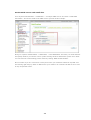
3.2 Network
TC P/IP
(i)
IP A d d r e s s
You can configure the TC P/IP settings of the NAS on this page. C lick the Edit button (
) to edit the
network settings. For the NAS which supports two LAN ports, you can connect both network
interfaces to two different switches and configure the TC P/IP settings. The NAS will acquire two IP
addresses which allow the access from two different subnets. This is known as multi-IP setting*.
When using Finder to detect the NAS IP, the IP of Ethernet 1 will be shown in LAN 1 only and the IP
of Ethernet 2 will be shown in LAN 2 only. To use port trunking mode for dual LAN connection, see
section (iii).
* TS-110, TS-119, TS-210, TS-219, and TS-219P provide one Giga LAN port only therefore do not
support dual LAN configuration or port trunking.
37
On the TC P/IP Property page, configure the following settings:
Ne two r k S p e e d
Select the network transfer rate according to the network environment to which the NAS is
connected. Select auto negotiation and the NAS will adjust the transfer rate automatically.
Ob ta in th e IP a d d r e s s s e ttin g s a u to m a tic a lly v ia DHCP
If your network supports DHC P, select this option and the NAS will obtain the IP address and
network settings automatically.
U s e s ta tic IP a d d r e s s
To use a static IP address for network connection, enter the IP address, subnet mask, and default
gateway.
E n a b le DHCP S e r v e r
If no DHC P is available on the LAN where the NAS locates, you can turn on this function to make the
NAS a DHC P server. The NAS will allocate dynamic IP address to the DHC P clients on the LAN.
38
You can set the range of IP addresses allocated by the DHC P server and the lease time. The lease
time refers to the time that an IP address is leased to the clients by the DHC P server. When the
lease time expires, the client has to acquire an IP address from the DHC P server again.
No te :
If there is an existing DHC P server on the LAN, do not enable this function. Otherwise, there
will be IP address conflicts and network access errors.
This option is available to Ethernet 1 only when both LAN ports of the dual LAN NAS are
connected to the network.
(ii)
De fa u lt G a te wa y
Select the gateway settings to use if you have connected both LAN ports to the network (dual LAN
NAS models only).
39
(iii) Po r t T r u n k in g
Applicable to NAS models with two LAN ports only. This feature is not supported by TS-110, TS-119,
TS-210, TS-219, and TS-219P.
The NAS supports port trunking which combines two Ethernet interfaces into one to increase the
bandwidth and offers load balancing and fault tolerance (also known as failover). Load balancing is a
feature which distributes the workload evenly across two Ethernet interfaces for higher redundancy.
Failover is the capability to switch over to a standby network interface (also known as the slave
interface) when the primary network interface (also known as the master interface) does not
correspond correctly to maintain high availability.
To use port trunking on the NAS, make sure both LAN ports of the NAS are connected to the same
switch and you have configured the settings described in sections (i) and (ii).
Follow the steps below to configure port trunking on the NAS:
1.
Select the option ‘Enable Network Port Trunking’.
2.
Choose a port trunking mode from the drop-down menu. The default option is Active
Backup (Failover).
3.
Click ‘Apply’.
40
4.
The Ethernet interfaces will be combined as Ethernet 1+2. Click the Edit button to edit
the network settings.
5.
After applying the settings, make sure the network cables of the two Ethernet
interfaces are connected to the correct switch and the switch has been configured to
support the port trunking mode selected on the NAS.
41
Refer to the table below about the port trunking options available on the NAS.
F ie ld
De s c r ip tio n
S witc h Re q u ir e d
Balance-rr
Round-Robin mode is good for general purpose load
Supports static
(Round-Robin)
balancing between two Ethernet interfaces. This mode
trunking. Make sure
transmits packets in sequential order from the first
static trunking is
available slave through the last. Balance-rr provides
enabled on the switch.
load balancing and fault tolerance.
Active Backup
Active Backup uses only one Ethernet interface. It
General switches
switches to the second Ethernet interface if the first
Ethernet interface does not work properly. Only one
interface in the bond is active. The bond’s MAC
address is only visible externally on one port (network
adapter) to avoid confusing the switch. Active Backup
mode provides fault tolerance.
Balance XOR
Balance XOR balances traffic by splitting up outgoing
Supports static
packets between the Ethernet interfaces, using the
trunking. Make sure
same one for each specific destination when possible.
static trunking is
It transmits based on the selected transmit hash policy. enabled on the switch.
The default policy is a simple slave count operating on
Layer 2 where the source MAC address is coupled with
destination MAC address. Alternate transmit policies
maybe selected via the xmit_hash_policy option.
Balance XOR mode provides load balancing and fault
tolerance.
Broadcast
Broadcast sends traffic on both network interfaces.
Supports static
This mode provides fault tolerance.
trunking. Make sure
static trunking is
enabled on the switch.
IEEE 802.3ad
Dynamic Link Aggregation uses a complex algorithm to
Supports 802.3ad
(Dynamic Link
aggregate adapters by speed and duplex settings. It
LAC P
Aggregation)
utilizes all slaves in the active aggregator according to
the 802.3ad specification. Dynamic Link Aggregation
mode provides load balancing and fault tolerance but
requires a switch that supports IEEE 802.3ad with LAC P
mode properly configured.
Balance-tlb
Balance-tlb uses channel bonding that does not require
(Adaptive
any special switch. The outgoing traffic is distributed
Transmit Load
according to the current load on each Ethernet interface
Balancing)
(computed relative to the speed). Incoming traffic is
received by the current Ethernet interface. If the
42
General switches
receiving Ethernet interface fails, the other slave takes
over the MAC address of the failed receiving slave.
Balance-tlb mode provides load balancing and fault
tolerance.
Balance-alb
Balance-alb is similar to balance-tlb but also attempts
(Adaptive Load
to redistribute incoming (receive load balancing) for
Balancing)
IPV4 traffic. This setup does not require any special
switch support or configuration. The receive load
balancing is achieved by ARP negotiation sent by the
local system on their way out and overwrites the
source hardware address with the unique hardware
address of one of the Ethernet interfaces in the bond
such that different peers use different hardware
address for the server. This mode provides load
balancing and fault tolerance.
43
General switches
(iv) DNS S e r v e r
Primary DNS Server: Enter the IP address of the primary DNS server.
Secondary DNS Server: Enter the IP address of the secondary DNS server.
No te :
Please contact your ISP or network administrator for the IP address of the primary and the
secondary DNS servers. When the NAS plays the role as a terminal and needs to perform
independent connection, for example, BT download, you must enter at least one DNS server
IP for proper URL connection. Otherwise, the function may not work properly.
If you select to obtain the IP address by DHC P, there is no need to configure the primary and
the secondary DNS servers. In this case, enter ‘0.0.0.0’.
(v)
Jumbo Frame Settings (MTU)
This feature is not supported by TS-509 Pro, TS-809 Pro, and TS-809U-RP.
‘Jumbo Frames’ refer to the Ethernet frames that are larger than 1500 bytes. It is designed to
enhance Ethernet networking throughput and reduce the C PU utilization of large file transfers by
enabling more efficient larger payloads per packet.
Maximum Transmission Unit (MTU) refers to the size (in bytes) of the largest packet that a given
layer of a communications protocol can transmit.
The NAS uses standard Ethernet frames: 1500 bytes by default. If your network appliances support
Jumbo Frame setting, select the appropriate MTU value for your network environment. The NAS
supports 4074, 7418, and 9000 bytes for MTU.
No te : The Jumbo Frame setting is valid in Gigabit network environment only. All the network
appliances connected must enable Jumbo Frame and use the same MTU value.
44
DDNS
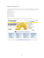
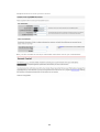
To set up a server on the Internet and enable the users to connect to it easily, a fixed and easy-toremember host name is often required. However, if the ISP provides only dynamic IP address, the
IP address of the server will change from time to time and is difficult to recall. You can enable the
DDNS service to solve the problem.
After enabling the DDNS service of the NAS, whenever the NAS restarts or the IP address is
changed, the NAS will notify the DDNS provider immediately to record the new IP address. When
the user tries to connect to the NAS by the host name, the DDNS will transfer the recorded IP
address to the user.
The NAS supports the DDNS providers: http://www.dyndns.com/, http://update.ods.org/, http://
www.dhs.org/, http://www.dyns.cx/, http://www.3322.org/, http://www.no-ip.com/.
For the information of setting up the DDNS and port forwarding on the NAS, see here 383 .
45
IPv 6
The NAS supports IPv6 connectivity with ‘stateless’ address configurations and RADVD (Router
Advertisement Daemon) for IPv6, RFC 2461 to allow the hosts on the same subnet to acquire IPv6
addresses from the NAS automatically. The NAS services which support IPv6 include:
Remote replication
Web Server
FTP
iSC SI (Virtual disk drives)
SSH (putty)
To use this function, select the option ‘Enable IPv6’ and click ‘Apply’. The NAS will restart. After the
system restarts, login the IPv6 page again. The settings of the IPv6 interface will be shown. C lick
the Edit button
to edit the settings.
46
IPv 6 A u to Co n fig u r a tio n
If you have an IPv6 enabled router on the network, select this option to allow the NAS to acquire the
IPv6 address and the configurations automatically.
U s e s ta tic IP a d d r e s s
To use a static IP address, enter the IP address (e.g. 2001:bc95:1234:5678), prefix length (e.g. 64),
and the gateway address for the NAS. You may contact your ISP for the information of the prefix
and the prefix length.
Enable Router Advertisement Daemon (radvd)
To configure the NAS as an IPv6 host and distribute IPv6 addresses to the local clients which
support IPv6, enable this option and enter the prefix and prefix length.
IPv 6 DNS s e r v e r
Enter the preferred DNS server in the upper field and the alternate DNS server in the lower field.
You may contact your ISP or network administrator for the information. If you select IPv6 auto
configuration, leave the fields as '::'.
47
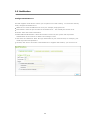
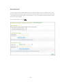
3.3 Hardware
You can set the hardware functions of the NAS.
E n a b le c o n fig u r a tio n r e s e t s witc h
When this function is turned on, you can press the reset button for 3 seconds to reset the
administrator password and the system settings to default. The disk data will be retained.
E n a b le h a r d d is k s ta n d b y m o d e
When this function is turned on, the HDD enters standby mode if there is no access within the
specified period.
48
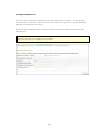
E n a b le lig h t s ig n a l a le r t wh e n th e fr e e s iz e o f S A T A d is k is le s s th a n th e v a lu e :
The status LED flashes red and green when this function is turned on and the free space of the SATA
HDD is less than the value. The range of the value is 1-51200 MB.
E n a b le wr ite c a c h e (fo r E XT 4 )
If the disk volume of the NAS is in EXT 4 format, you can gain better write performance by turning
on this option. Note that an unexpected system shutdown may lead to incomplete data transfer
when data write is in process. This option will be turned off when any of the following services is
enabled: Download Station, MySQL service, user quota, and Surveillance Station. You are
recommended to turn this option off if the NAS is set as a shared storage in a virtualized or clustered
environment.
E n a b le a la r m b u z z e r
You can select to turn on the alarm buzzer when system operation (startup, shutdown, and firmware
upgrade) and system events (error and warning) occur.
S m a r t F a n Co n fig u r a tio n
(i) Enable smart fan (recommended)
Select to use the default smart fan settings or define the settings manually. When the system
default settings are selected, the fan rotation speed is automatically adjusted when the server
temperature, C PU temperature, and hard drive temperature meet the criteria. It is
recommended to enable this option.
(ii) Set fan rotation speed manually
By manually setting the fan rotation speed, the fan rotates at the defined speed continuously.
49
E n a b le wa r n in g a le r t fo r r e d u n d a n t p o we r s u p p ly o n th e we b - b a s e d in te r fa c e :
If you have installed two power supply units (PSU) on the NAS and connected them to the power
sockets, both PSU will supply the power to the NAS (applied to 1U and 2U models). You can turn on
redundant power supply mode in ‘System Administration’ > ‘Hardware’ to receive warning alert for
the redundant power supply. The NAS will sound and record the error messages in ‘System Logs’
when the PSU is plugged out or does not correspond correctly.
If you have installed only one PSU on the NAS, you are suggested NOT to enable this option.
* This function is disabled by default.
50
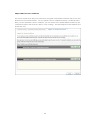
3.4 Security
Se c urity Le v e l
Enter the IP address or network domain from which the connections to this server are allowed or
denied. When the connection of a host server is denied, all the protocols of that server are not
allowed to connect to the local server.
After changing the settings, click ‘Apply’ to save the changes. The network services will be restarted
and current connections to the server will be terminated.
51
Ne twork Ac c e ss Prote c tion
The network access protection enhances system security and prevents unwanted intrusion. You can
select to block the IP for a certain period of time or forever if the IP fails to login the server from a
particular connection method.
52
Im port SSL Se c ure C e rtific a te
The Secure Socket Layer (SSL) is a protocol for encrypted communication between web servers and
browsers for secure data transfer. You can upload a secure certificate issued by a trusted provider.
After you have uploaded a secure certificate, you can connect to the administration interface by SSL
connection and there will not be any alert or error message. The NAS supports X.509 certificate and
private key only.
53
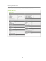
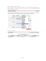
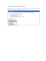
3.5 Notification
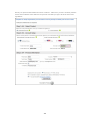
C onfigure SMTP Se rv e r
The NAS supports email alert to inform you of system errors and warning. To receive the alert by
email, configure the SMTP server.
SMTP Server: Enter the SMTP server name, for example, smtp.gmail.com.
Port Number: Enter the port number for the SMTP server. The default port number is 25.
Sender: Enter the sender information.
Enable SMTP Authentication: When this function is turned on, the system will request the
authentication of the mail server before the message is sent.
User Name and Password: Enter the login information of your email account, for example, your
Gmail login name and password.
Use SSL/ TLS secure connection: If the SMTP server supports this function, you can turn it on.
54
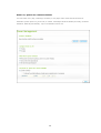
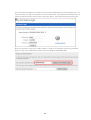
C onfigure SMS Se rv e r
You can configure SMS server settings to send SMS messages from the NAS. The default SMS
service provider is C lickatell. You can add your own SMS service provider by selecting ‘Add SMS
Provider’ from the drop-down menu.
When you select ‘Add SMS service provider’, enter the name of the SMS provider and the URL
template text.
No te : You will not be able to receive the SMS properly if the URL template text entered does not
follow the standard of your SMS service provider.
55
Ale rt Notific a tion
You can select to receive instant SMS or email alert when a system error or warning occurs. Enter
the email address and mobile phone number to receive the alerts. Make sure you have entered the
correct SMTP server and the SMSC server settings. If you do not want to receive any alerts, select
‘No alert’ for both settings.
For more information, see here 391 .
56
3.6 Power Management
You can restart or shut down the NAS, specify the behaviour of the NAS after a power recovery, and
set the schedule for automatic system power on/ off/ restart on this page.
Restart/ Shutdown
Restart or shut down the NAS immediately.
If you try to restart or turn off the NAS from the web-based interface or the LC D panel when a
remote replication job is in process, the NAS will prompt you to ignore the running replication job or
not.
Turn on the option ‘Postpone the restart/shutdown schedule when replication job is in process’ to
allow the scheduled system restart or shutdown to be carried out after a running replication job
completes. Otherwise, the NAS will ignore the running replication job and execute scheduled system
restart or shutdown.
Wake on LAN
Turn on this option to allow the users to power on the NAS remotely by Wake on LAN. Note that if
the power connection is physically removed (in other words, the power cable is unplugged) when the
NAS is turned off, Wake on LAN will not function whether or not the power supply is reconnected
afterwards.
This feature is not supported by TS-110, TS-119, TS-210, TS-219, TS-219P, TS-410, TS-419P, TS410U, and TS-419U.
Power resumption settings
C onfigure the NAS to resume to the previous power-on or power-off status, turn on or remain off
when the AC power resumes after a power outage.
57
Power on/ power off/ restart schedule
You can select every day, weekdays, weekend, or any days of the week and set the time for
automatic system power on, power off, or restart. Weekdays stand for Monday to Friday; weekend
stands for Saturday and Sunday. Up to 15 schedules can be set.
58
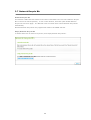
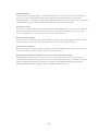
3.7 Network Recycle Bin
Ne two r k Re c y c le Bin
This function enables the files deleted on the shares of the NAS to be removed to Network Recycle
Bin to reserve the files temporarily. To turn on this function, select the option ‘Enable Network
Recycle Bin’ and click ‘Apply’. The NAS will create a network share named ‘Network Recycle Bin’
automatically.
Note that Network Recycle Bin only supports file deletion via SAMBA and AFP.
E m p ty Ne two r k Re c y c le Bin
To delete all the files in network recycle bin, click 'Empty Network Recycle Bin'.
59
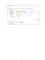
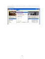
3.8 Backup/ Restore Settings
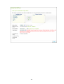
Ba c k u p S y s te m S e ttin g s
To back up all the settings, including the user accounts, server name, network configuration and so
on, click ‘Backup’ and select to open or save the setting file.
Re s to r e S y s te m S e ttin g s
To restore all the settings, click ‘Browse’ to select a previously saved setting file and click ‘Restore’.
60
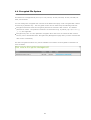
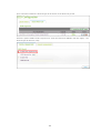
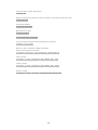
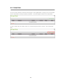
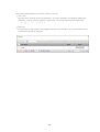
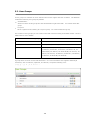
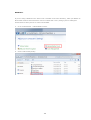
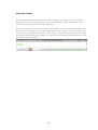
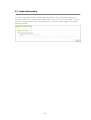
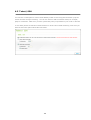
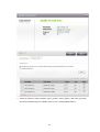
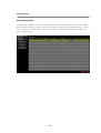
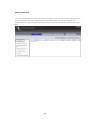
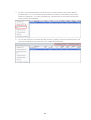
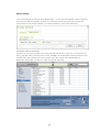
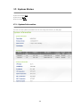
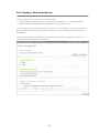
3.9 System Logs
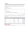
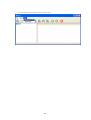
Sy ste m Ev e nt Logs
The NAS can store 10,000 recent event logs, including warning, error, and information messages. If
the NAS does not correspond correctly, you can refer to the event logs for troubleshooting.
T ip : You can right click a log and delete the record.
61
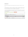
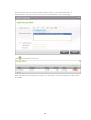
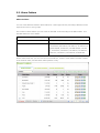
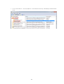
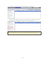
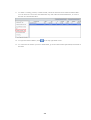
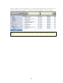
Sy ste m C onne c tion Logs
The NAS supports recording HTTP, FTP, Telnet, SSH, AFP, NFS, SAMBA, and iSC SI connections.
C lick ‘Options’ to select the connection type to be logged.
The file transfer performance can be slightly affected when this feature is turned on.
T ip : You can right click a log and select to delete the record or block the IP and select how long the
IP should be blocked.
Archive logs: Turn on this option to archive the connection logs. The NAS generates a C SV file
automatically and saves it to a specified folder when the number of logs reaches the upper limit.
62
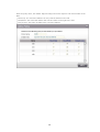
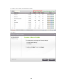
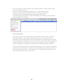
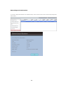
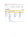
O n- line Use rs
The information of the on-line users connecting to the NAS by networking services is shown on this
page.
Tip: You can right click a log and select to disconnect the IP connection and block the IP.
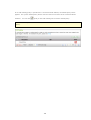
Sy slog
Syslog is a standard for forwarding the log messages on an IP network. You can turn on this option
to save the event logs and connection logs to a remote syslog server.
63
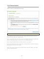
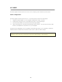
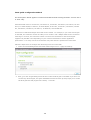
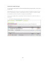
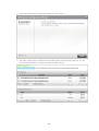
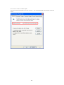
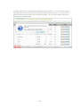
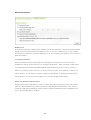
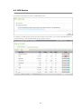
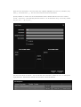
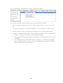
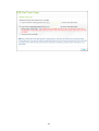
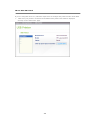
3.10 Firmware Update
U p d a te F ir m wa r e b y W e b A d m in is tr a tio n Pa g e
No te : If the system is running properly, you do not need to update the firmware.
Before updating the system firmware, make sure the product model and firmware version are
correct. Follow the steps below to update firmware:
Step 1: Download the release notes of the firmware from the QNAP website http://www.qnap.com/.
Read the release notes carefully to make sure you need to update the firmware.
Step 2: Download the NAS firmware and unzip the IMG file to your computer.
Step 3: Before updating the system firmware, back up all the disk data on the server to avoid any
potential data loss during the system update.
Step 4: C lick ‘Browse’ to select the correct firmware image for the system update. C lick ‘Update
System’ to update the firmware.
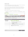
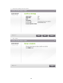
64
The system update may take tens of seconds to several minutes to complete depending on the
network connection status. Please wait patiently. The NAS will inform you when the system update
has completed.
65
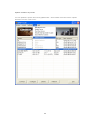
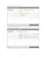
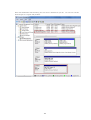
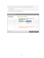
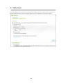
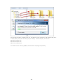
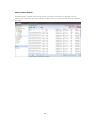
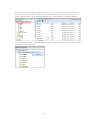
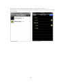
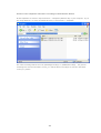
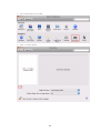
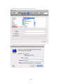
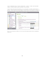
U p d a te F ir m wa r e b y F in d e r
You can update the system firmware by QNAP Finder. Select a NAS model and choose ‘Update
Firmware’ from the ‘Tools’ menu.
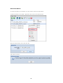
66
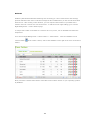
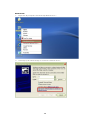
Login the NAS as a user with administrator access right.
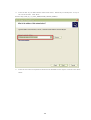
Browse and select the firmware for the NAS. C lick ‘Start’ to update the system.
No te : You can use Finder to update all the servers of the same model on the same local
network at the same time. Make sure you have administrator access to all the servers you want
to update.
67
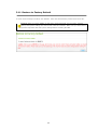
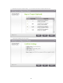
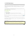
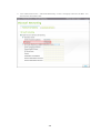
Liv e Upda te
Select 'Enable QNAP live update' to allow the NAS to automatically check if a new firmware version is
available for download from the Internet. If a new firmware is found, you will be notified after
logging in the NAS as an administrator.
You can click 'C HEC K FOR UPDATE' to check if any firmware update is available.
Note that the NAS must be connected to the Internet for these features to work.
68
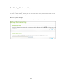
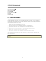
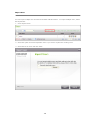
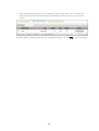
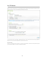
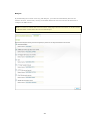
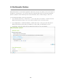
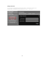
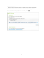
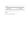
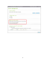
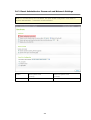
3.11 Restore to Factory Default
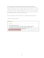
To reset all the settings to default, click ‘RESET’. Enter the administrator password and click 'OK'.
Ca u tio n : When you press ‘RESET’ on this page, all the disk data, user accounts, network
shares, and system settings are cleared and restored to default. Make sure you have backed
up all the important data and system settings before resetting the NAS.
69
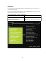
4. Disk Management
Volume Management 70
RAID Management 74
HDD SMART 96
Encrypted File System 97
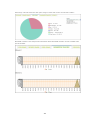
iSC SI 98
Virtual Disk 135
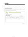
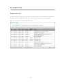
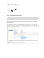
4.1 Volume Management
This page shows the model, size, and current status of the HDD on the NAS. You can format and
check the HDD, and scan bad blocks on the HDD. When the HDD has been formatted, the NAS will
create the following default share folders:
Public: Share folder for file sharing by everyone.
Qdownload/ Download*: The default share folder for Download Station.
Qmultimedia/ Multimedia*: The default share folder for Multimedia Station.
Qusb/ Usb*: The default share folder for data copy function via the USB ports.
Qweb/ Web*: The default share folder for Web Server.
Qrecordings/ Recordings*: The default share folder for Surveillance Station.
*The default network shares of TS-x59 Turbo NAS series are Public, Download, Multimedia, Usb,
Web, and Recordings.
No te : The default share folders are created on the first disk volume and the directory cannot be
changed.
70
Dis k Co n fig u r a tio n
A p p lie d NA S Mo d e ls
Single disk volume
All models
RAID 1, JBOD (just a bunch of disks)
2-bay models or above
RAID 5, RAID 6, RAID 5+hot spare
4-bay models or above
RAID 6+hot spare
5-bay models or above
71
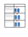
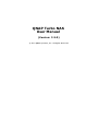
S ingle D isk Volume
Each HDD is used as a standalone disk. If a
HDD is damaged, all the data will be lost.
J BO D ( J ust a bunch of disks)
JBOD is a collection of HDD that does not
offer any RAID protection. The data are
written to the physical disks sequentially.
The total storage capacity equals to the sum
of the capacity of all member HDD.
RAID 0 S triping D isk Volume
RAID 0 (striping disk) combines 2 or more
HDD into one larger volume. The data is
written to the HDD without any parity
information and no redundancy is offered.
The disk capacity equals the number of HDD
in the array times the size of the smallest
HDD.
RAID 1 Mirroring D isk Volume
RAID 1 duplicates the data between two HDD
to provide disk mirroring. To create a RAID
1 array, a minimum of 2 HDD are required.
72
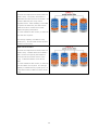
RAID 5 D isk Volume
The data are striped across all the HDD in a
RAID 5 array. The parity information is
distributed and stored across each HDD. If a
member HDD fails, the array enters
degraded mode. After installing a new HDD
to replace the failed one, the data can be
rebuilt from other member drives that
contain the parity information.
To create a RAID 5 disk volume, a minimum
of 3 HDD are required.
The storage capacity of a RAID 5 array
equals (N-1). N is the total number of HDD
members in the array.
RAID 6 D isk Volume
The data are striped across all the HDD in a
RAID 6 array. RAID 6 differs from RAID 5
that a second set of parity information is
stored across the member drives in the
array. It tolerates failure of two drives
HDD.
To create a RAID 6 disk volume, a minimum
of 4 hard disks are required. The storage
capacity of a RAID 6 array equals (N-2). N
is the total number of HDD members in the
array.
73
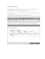
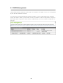
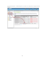
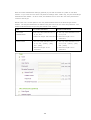
4.2 RAID Management
*Online RAID capacity expansion, online RAID level migration, and RAID recovery are not supported
by one-bay NAS models and TS-210.
You can perform online RAID capacity expansion (RAID 1/ 5/ 6) and online RAID level migration
(single disk/ RAID 1/ RAID 5), add a HDD member to a RAID 5 or RAID 6 configuration, configure a
spare HDD (RAID 5/ 6) with the data retained, enable Bitmap, and recover a RAID configuration on
this page.
74
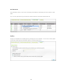
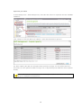
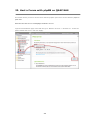
Ex pa nd C a pa c ity (O nline RAID C a pa c ity Ex pa nsion)
S c e n a r io
You bought four 250GB HDD for initial setup of TS-509 Pro and configured RAID 5 disk configuration
with the four HDD.
A half year later, the data size of the department has largely increased to 1.5TB. In other words,
the storage capacity of the NAS is running out of use. At the same time, the price of 1TB hard drives
has dropped to a large extent.
75
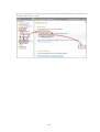
Op e r a tio n p r o c e d u r e
In ‘Disk Management’ > ‘RAID Management’, select the disk volume for expansion and click ‘EXPAND
C APAC ITY’.
C lick ‘C hange’ for the first HDD to be replaced. Follow the instructions to proceed.
Tip: After replacing the HDD, the description field shows the message ‘You can replace this drive’.
This means you can replace the HDD to a larger one or skip this step if the HDD have been replaced
already.
Ca u tio n : When the hard drive synchronization is in process, do NOT turn off the NAS or
plug in or unplug the hard disk drives.
76
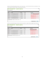
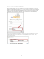
When the description displays ‘Please remove this drive’, remove the hard drive from the NAS. Wait
for the NAS to beep twice after removing the hard drive.
When the description displays ‘Please insert the new drive’, plug in the new HDD to the drive slot.
77
After plugging in the HDD, wait for the NAS to beep. The system starts rebuilding.
After rebuilding finishes, repeat the steps above to replace other HDD.
78
After changing the HDD and rebuilding completes, you can click ‘EXPAND C APAC ITY’ to execute
RAID expansion.
C lick ‘OK’ to proceed.
The NAS beeps and starts to expand the capacity.
79
The process may take from hours to tens of hours to finish depending on the drive size. Please wait
patiently for the process to finish. Do NOT turn off the power of NAS.
After RAID expansion has finished, the new capacity is shown and the status is ‘Ready’. You can
start to use the larger capacity. (In the example you have 3.7TB logical volume)
Tip: If the description still shows ‘You can replace this hard drive’ and the status of the drive volume
says ‘Ready’, it means the RAID volume is still expandable.
80
Migra te (O nline RAID Le v e l Migra tion)
During the initial setup of TS-509 Pro, you bought a 1TB HDD and configured it as single disk. TS509 Pro is used as a file server for data sharing among the departments.
After a half year, more and more important data are saved on TS-509 Pro. There is a rising concern
for hard drive damage and data loss. Therefore, you planned to upgrade the disk configuration to
RAID 5.
Using online RAID level migration, you can install one HDD for setting up TS-509 Pro and upgrade
the RAID level in the future. The migration process can be done without turning off the server. All
the data will be retained.
You can do the following with online RAID level migration:
Migrate the systeom from single disk to RAID 1, RAID 5, or RAID 6
Migrate the system from RAID 1 to RAID 5 or RAID 6
Migrate the system from RAID 5 with 3 HDD to RAID 6
You need to:
Prepare the HDD of the same or larger capacity as an existing drive in the RAID configuration.
Execute RAID level migration (migrate the system from single disk mode to RAID 5 with 4 HDD).
81
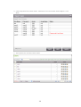
Go to ‘Disk Management’ > ‘Volume Management’. The current disk volume configuration displayed
on the page is single disk (the capacity is 1TB).
82
Plug in the new 1TB HDDs to drive slots 2, 3, 4 and 5 of NAS. The NAS will detect the new HDDs.
The status of the new HDDs is ‘Unmounted’.
83
Go to ‘Disk Management’ > ‘RAID Management’, select the drive configuration for migration and click
‘Migrate’.
84
Select one or more available drives and the migration method. The drive capacity after migration is
shown. C lick ‘Migrate’.
Note that all the data on the selected HDD will be cleared. C lick ‘OK’ to confirm.
85
When migration is in process, the required time and total drive capacity after migration are shown in
the description field.
86
The NAS will enter ‘Read only’ mode when migration is in process during 11%–49% to assure the
data of the RAID configuration will be consistent after RAID migration completes.
After migration completes, the new drive configuration is shown (RAID 5 now) and the status is
Ready. You can start to use the new drive configuration.
The process may take from hours to tens of hours to finish depending on the HDD size. You can
connect to the web page of the NAS to check the status later.
87
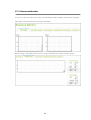
Use O nline RAID C a pa c ity Ex pa nsion a nd O nline RAID Le v e l Migra tion
S c e n a r io
You had a tight schedule to set up the file server and FTP server. However, you had only one 250GB
HDD. Therefore, you set up the TS-509 Pro with the single disk configuration.
The original plan was to set up a 3TB RAID 5 network data centre with TS-509 Pro.
You now planned to upgrade the disk configuration of TS-509 Pro to RAID 5 and expand the total
storage capacity to 3TB with all the original data retained after the HDD are purchased.
Execute online RAID level migration to migrate the system from single disk to RAID 5. The total
storage capacity will be 750GB, RAID 5 (with one 250GB HDD and three 1TB HDD, the disk usage
will be 250GB*4 for RAID 5.). You can refer to the previous step for the operation procedure.
Execute online RAID capacity expansion to replace the 250GB HDD with a new 1TB HDD, and then
expand the logical volume from 750GB to 3TB of RAID 5. You can refer to the previous step for the
operation procedure.
88
Add ha rd driv e
Follow the steps below to add a HDD member to a RAID 5 or RAID 6 disk configuration.
1.
Make sure the status of the RAID 5 or RAID 6 configuration is 'Ready'.
2.
Install a HDD on the NAS. If you have a HDD which has already been formatted as single disk
volume on the NAS, you can add this HDD to the RAID 5 or RAID 6 configuration. You are
recommended to use hard disk drives of the same storage capacity for the RAID
configuration.
3.
Select the RAID 5 or RAID 6 configuration on the 'RAID Management' page and click 'ADD
HARD DRIVE'.
4.
Select the new HDD member. The total drive capacity after adding the drive will be shown.
C lick 'ADD HARD DRIVE'.
5.
All the data on the new HDD member will be deleted during this process. The data on the
original RAID 5 or RAID 6 configuration will be retained. C lick 'OK'. The NAS will beep twice.
This process may take a few hours to tens of hours to complete depending on the number and the
size of the HDD. Please wait patiently for the process to finish. Do NOT turn off the NAS during this
process. You can use a RAID configuration of larger capacity after the process.
89
C onfigure Spa re Driv e
You can add a spare drive to or remove a spare drive from a RAID 5 configuration.
Follow the steps below to use this feature.
1.
Make sure the status of the RAID 5 or RAID 6 configuration is 'Ready'.
2.
To add a spare drive, install a HDD on the NAS. If you have a HDD which has already been
formatted as single disk volume on the NAS, you can configure this HDD as the spare drive.
You are recommended to use hard disk drives of the same storage capacity for the RAID
configuration.
3.
Select the HDD and click 'C ONFIGURE SPARE DRIVE'.
4.
To add a spare drive to the selected configuration, select the HDD and click 'C ONFIGURE
SPARE DRIVE'. All the data on the selected HDD will be deleted. C lick 'OK' to proceed.
5.
To remove a spare drive, unselect the spare drive and click 'C ONFIGURE SPARE DRIVE'.
The original data on the RAID 5 or RAID 6 disk volume will be retained. After the configuration
completes, the status of the disk volume will become 'Ready'.
90
B itm a p
Bitmap improves the time for RAID rebuilding after an unexpected error, or removing or re-adding a
member HDD of the RAID configuration. If an array has a bitmap, the member HDD can be
removed and re-added and only blocks changes since the removal (as recorded in the bitmap) will
be re-synchronized. To use this feature, select a RAID 1, 5, or 6 disk volume and click 'ENABLE
BITMAP'.
No te : Bitmap support is only available for RAID 1, 5, and 6.
91
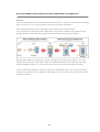
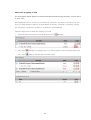
Re c ov e r (RAID Re c ov e ry )
RAID Recovery: When the NAS is configured as RAID 5 (or RAID 6) and 2 (or 3) HDD are uplugged
from the server accidentally, you can plug in the same HDD into the same drive slots and click
‘Recover’ to recover the volume status from ‘Not active’ to ‘Degraded mode’.
If the disk volume is configured as RAID 0 or JBOD and one or more of the HDD members are
disconnected, you can use this function to recover the volume status from ‘Not active’ to ‘Normal’.
The disk volume can be used normally after successful recovery.
No te : If the disconnected drive member is damaged, the RAID recovery function will not work.
S ta n d a r d RA ID 5 QNA P RA ID 5
S ta n d a r d RA ID 6 QNA P RA ID 6
Degraded mode
N-1
N-1
N-1 & N-2
N-1 & N-2
Read Only
N/A
N-1, bad blocks
N/A
N-2, bad blocks
Protection (for
found in the
found in the
immediate data
surviving HDD of
surviving HDD of
backup & HDD
the array.
the array.
replacement)
RAID Recovery
N/A
If re-plugging in
N/A
If re- plugging in
(RAID Status: Not
all original HDD to
all original HDD to
Active)
the NAS and they
the NAS and they
can be spun up,
can be spun up,
identified,
identified,
accessed, and the
accessed, and the
HDD superblock is
HDD superblock is
not damaged.
not damaged).
RAID C rash
N-2
N-2 failed HDD
N-3
N-3 and any of
and any of the
the remaining
remaining HDD
HDD cannot be
cannot be spun
spun up/
up/ identified/
identified/
accessed.
accessed.
N = Number of hard disk drives (HDD) in the array
92
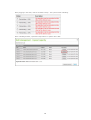
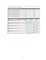
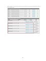
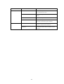
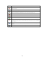
F u r th e r in fo r m a tio n a b o u t RA ID m a n a g e m e n t o f th e NA S :
The NAS supports the following actions according to the number of HDD and disk configurations
supported. Please refer to the following table for the details.
Or ig in a l Dis k
Co n fig u r a tio n
Ne w Dis k
No . o f Ne w HDD
A c tio n
* No . o f HDD
Co n fig u r a tio n *
No . o f HDD
RAID 5 * 3
1
Add HDD member
RAID 5 * 4
RAID 5 * 3
2
Add HDD member
RAID 5 * 5
RAID 5 * 3
3
Add HDD member
RAID 5 * 6
RAID 5 * 3
4
Add HDD member
RAID 5 * 7
RAID 5 * 3
5
Add HDD member
RAID 5 * 8
RAID 5 * 4
1
Add HDD member
RAID 5 * 5
RAID 5 * 4
2
Add HDD member
RAID 5 * 6
RAID 5 * 4
3
Add HDD member
RAID 5 * 7
RAID 5 * 4
4
Add HDD member
RAID 5 * 8
RAID 5 * 5
1
Add HDD member
RAID 5 * 6
RAID 5 * 5
2
Add HDD member
RAID 5 * 7
RAID 5 * 5
3
Add HDD member
RAID 5 * 8
RAID 5 * 6
1
Add HDD member
RAID 5 * 7
RAID 5 * 6
2
Add HDD member
RAID 5 * 8
RAID 5 * 7
1
Add HDD member
RAID 5 * 8
RAID 6 * 4
1
Add HDD member
RAID 6 * 5
RAID 6 * 4
2
Add HDD member
RAID 6 * 6
RAID 6 * 4
3
Add HDD member
RAID 6 * 7
RAID 6 * 4
4
Add HDD member
RAID 6 * 8
RAID 6 * 5
1
Add HDD member
RAID 6 * 6
RAID 6 * 5
2
Add HDD member
RAID 6 * 7
RAID 6 * 5
3
Add HDD member
RAID 6 * 8
RAID 6 * 6
1
Add HDD member
RAID 6 * 7
RAID 6 * 6
2
Add HDD member
RAID 6 * 8
RAID 6 * 7
1
Add HDD member
RAID 6 * 8
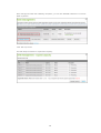
RAID 1 * 2
1
Online RAID capacity
expansion
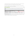
93
RAID 1 * 2
Online RAID capacity
RAID 5 * 3
1
RAID 5 * 4
1
RAID 5 * 5
1
RAID 5 * 6
1
RAID 5 * 7
1
RAID 5 * 8
1
RAID 6 * 4
1
RAID 6 * 5
1
RAID 6 * 6
1
RAID 6 * 7
1
RAID 6 * 8
1
Single * 1
1
Online RAID level migration RAID 1 * 2
Single * 1
2
Online RAID level migration RAID 5 * 3
Single * 1
3
Online RAID level migration RAID 5 * 4
Single * 1
4
Online RAID level migration RAID 5 * 5
Single * 1
5
Online RAID level migration RAID 5 * 6
Single * 1
6
Online RAID level migration RAID 5 * 7
Single * 1
7
Online RAID level migration RAID 5 * 8
Single * 1
3
Online RAID Level Migration RAID 6 * 4
Single * 1
4
Online RAID level migration RAID 6 * 5
Single * 1
5
Online RAID level migration RAID 6 * 6
Single * 1
6
Online RAID level migration RAID 6 * 7
Single * 1
7
Online RAID level migration RAID 6 * 8
RAID 1 * 2
1
Online RAID level migration RAID 5 * 3
expansion
Online RAID capacity
expansion
Online RAID capacity
expansion
Online RAID capacity
expansion
Online RAID capacity
expansion
Online RAID capacity
expansion
Online RAID capacity
expansion
Online RAID capacity
expansion
Online RAID capacity
expansion
Online RAID capacity
expansion
Online RAID capacity
expansion
94
RAID 5 * 3
RAID 5 * 4
RAID 5 * 5
RAID 5 * 6
RAID 5 * 7
RAID 5 * 8
RAID 6 * 4
RAID 6 * 5
RAID 6 * 6
RAID 6 * 7
RAID 6 * 8
RAID 1 * 2
2
Online RAID level migration RAID 5 * 4
RAID 1 * 2
3
Online RAID level migration RAID 5 * 5
RAID 1 * 2
4
Online RAID level migration RAID 5 * 6
RAID 1 * 2
5
Online RAID level migration RAID 5 * 7
RAID 1 * 2
6
Online RAID level migration RAID 5 * 8
RAID 1 * 2
2
Online RAID level migration RAID 6 * 4
RAID 1 * 2
3
Online RAID level migration RAID 6 * 5
RAID 1 * 2
4
Online RAID level migration RAID 6 * 6
RAID 1 * 2
5
Online RAID level migration RAID 6 * 7
RAID 1 * 2
6
Online RAID level migration RAID 6 * 8
RAID 5 * 3
1
Online RAID level migration RAID 6 * 4
RAID 5 * 3
2
Online RAID level migration RAID 6 * 5
RAID 5 * 3
3
Online RAID level migration RAID 6 * 6
RAID 5 * 3
4
Online RAID level migration RAID 6 * 7
RAID 5 * 3
5
Online RAID level migration RAID 6 * 8
95
4.3 HDD SMART
You can monitor the HDD health, temperature, and the usage status by HDD S.M.A.R.T. (SelfMonitoring Analysis and Reporting Technology).
You can view the following information of each HDD on the NAS.
F ie ld
De s c r ip tio n
Summary
Display the HDD S.M.A.R.T. summary and the latest test result.
Hard disk
Display the HDD details, for example, model, serial number, HDD capacity.
information
SMART
Display the HDD S.M.A.R.T. information. Any items that the values are lower
information
than the threshold are regarded as abnormal.
Test
Perform quick or complete HDD S.M.A.R.T. test.
Settings
C onfigure temperature alarm. When the HDD temperature is over the preset
values, the NAS records the error logs.
You can also set the quick and complete test schedule. The latest test result is
shown on the Summary page.
96
4.4 Encrypted File System
This feature is not supported by TS-110, TS-119, TS-210, TS-219, TS-219P, TS-410, TS-419P, TS410U, and TS-419U.
You can manage the encrypted disk volumes on the NAS on this page. Each encrypted disk volume
is locked by a particular key. The encrypted volume can be unlocked by the following methods:
Encryption Password: Enter the encryption password to unlock the disk volume. The default
password is ‘admin’. The password must be 8-16 characters long. Symbols (! @ # $ % ^ & * ( )
_+ = ?) are supported.
Encryption Key File: You can upload the encryption file to the server to unlock the disk volume.
The key can be downloaded from ‘Encryption Key Management’ page after you have unlocked the
disk volume successfully.
The data encryption functions may not be available in accordance to the legislative restrictions of
some countries.
97
4.5 iSCSI
The NAS supports built-in iSC SI service for server clustering and virtualized environments.
iSC SI C onfigura tion
The NAS supports built-in iSC SI service. To use this function, follow the steps below:
1.
Install an iSC SI initiator on your computer (Windows PC , Mac, or Linux).
2.
Enable iSC SI Target Service on the NAS and create a new iSC SI target.
3.
Run the iSC SI initiator and connect to the iSC SI target (NAS).
4.
After successful logon, format the iSC SI target (disk volume). You can start to use the disk
volume on the NAS as a virtual drive on your computer.
In between the relationship of your computer and the storage device, your computer is called an
initiator because it initiates the connection to the device, which is called a target.
No te : It is suggested NOT to connect to the same iSC SI target with two different clients (iSC SI
initiators) at the same time, because this may lead to data damage or disk damage.
98
T h e d e s c r ip tio n b e lo w a p p lie s to n o n In te l- b a s e d NA S o r In te l- b a s e d NA S m o d e ls
r u n n in g fir m wa r e p r io r to v e r s io n 3 .2 .0 o n ly .
Non Intel-based NAS refers to TS-110, TS-119, TS-210, TS-219, TS-219P, TS-410, TS-419P, TS410U, TS-419U. Intel-based NAS refers to TS-239 Pro, TS-239 Pro II, TS-259 Pro, SS-439 Pro, TS439 Pro, TS-439 Pro II, TS-439U-SP/RP, TS-459 Pro, TS-459U-SP/RP, TS-509 Pro, TS-559 Pro, TS639 Pro, TS-659 Pro, SS-839 Pro, TS-859 Pro, TS-809 Pro, TS-809U-RP, and TS-859U-RP.
Follow the steps below to create iSC SI targets and LUN on the NAS.
A logical unit number (LUN) will be created for each iSC SI target you create. A maximum of 4
targets and 4 LUNs can be created.
Under the tab ‘iSC SI TARGET LIST’, click ‘C reate New iSC SI Target’.
Enter the information required. Specify the target name. Specify the volume on which the iSC SI
target will be created on and the size of the target, also whether or not to pre-allocate the disk
space.
99
Enter the C HAP authentication settings (optional) if your NAS is located on a public or untrusted
network. If you enter the user name and password settings under ‘C HAP’ only, only the iSC SI target
authenticates the initiator. In other words, the initiators have to enter the user name password to
connect to the target.
Mutual C HAP: Turn on this option for two-way authentication between the iSC SI target and the
initiator. The target authenticates the initiator using the first set of user name and password. The
initiator authenticates the target using the ‘Mutual C HAP’ settings.
F ie ld
U s e r n a m e lim ita tio n
Pa s s wo r d lim ita tio n
Use C HAP
The only valid characters are 0-
The only valid characters are 0-
authentication
9, a-z, A-Z
9, a-z, A-Z
Maximum length: 256 characters
Maximum length: 12-16
characters
Mutual C HAP
The only valid characters are 0-
The only valid characters are 0-
9, a-z, A-Z, : (colon), . (dot),
9, a-z, A-Z, : (colon), . (dot),
and - (dash)
and - (dash)
Maximum length: 12-16
Maximum length: 12-16
characters
characters
100
Upon successful creation the iSC SI target will be shown on the iSC SI Target List.
Select the option ‘Enable iSC SI Target Service’ under the tab ‘iSC SI TARGET’ and click ‘Apply’. The
iSC SI target will become ready.
101
iSC SI Q uic k C onfigura tion Wiza rd
T h e d e s c r ip tio n b e lo w a p p lie s to In te l- b a s e d NA S m o d e ls r u n n in g fir m wa r e v e r s io n 3 .2 .0
o r la te r o n ly .
Intel-based NAS refers to TS-239 Pro, TS-239 Pro II, TS-259 Pro, SS-439 Pro, TS-439 Pro, TS-439
Pro II, TS-439U-SP/RP, TS-459 Pro, TS-459U-SP/RP, TS-509 Pro, TS-559 Pro, TS-639 Pro, TS-659
Pro, SS-839 Pro, TS-859 Pro, TS-809 Pro, TS-809U-RP, and TS-859U-RP.
A maximum of 256 iSC SI targets and LUNs can be created. For example, if you create 100 targets
on the NAS, the maximum number of LUNs you can create is 156. Multiple LUNs can be created for
each target. However, the maximum number of concurrent connections to the iSC SI targets
supported by the NAS varies depending on your network infrastructure and the application
performance. Too many concurrent connections may slow down the performance of the NAS.
Follow the steps below to configure the iSC SI target service on the NAS.
1.
Under the ‘Portal Management’ tab enable iSC SI target service. Apply the settings.
2.
Next, go to the ‘Target Management’ tab and create iSC SI targets on the NAS. If you have not
created any iSC SI targets, the Quick Installation Wizard will show up and prompt you to create
iSC SI targets and LUN (Logical unit number). C lick ‘OK’.
102
3.
Select to create an iSC SI target with a mapped LUN, an iSC SI target only, or an iSC SI LUN
only. C lick ‘Next’.
4.
C reate iSC SI target with a mapped LUN:
C lick 'Next'.
103
5.
Enter the target name and target alias. You may check the options 'Data Digest' and/or
'Header Digest' (optional). These are the parameters that the iSC SI initiator will be verified
when it attempts to connect to the iSC SI target.
104
6.
Enter the C HAP authentication settings. If you enter the user name and password settings
under 'Use C HAP authentication' only, only the iSC SI target authenticates the initiator, i.e. the
initiators have to enter the user name password settings here to access the target.
Mutual C HAP: Enable this option for two-way authentication between the iSC SI target and the
initiator. The target authenticates the initiator using the first set of user name and password. The
initiator authenticates the target using the 'Mutual C HAP' settings.
F ie ld
U s e r n a m e lim ita tio n
Pa s s wo r d lim ita tio n
Use C HAP
The only valid characters are 0-
The only valid characters are 0-
authentication
9, a-z, A-Z
9, a-z, A-Z
Maximum length: 256
Maximum length: 12-16
characters
characters
The only valid characters are 0-
The only valid characters are 0-
9, a-z, A-Z, : (colon), . (dot),
9, a-z, A-Z, : (colon), . (dot),
and - (dash)
and - (dash)
Maximum length: 12-16
Maximum length: 12-16
characters
characters
Mutual C HAP
105
7.
C reate an iSC SI LUN.
An iSC SI LUN is a logical volume mapped to the iSC SI target. Select one of the following modes to
allocate the disk space to the LUN:
Thin Provisioning: Select this option to allocate the disk space in a flexible manner. You can
allocate the disk space to the target anytime regardless of the current storage capacity available
on the NAS. Over-allocation is allowed since the storage capacity of the NAS can be expanded
by online RAID capacity expansion.
Instant Allocation: Select this option to allocate the disk space to the LUN instantly. This option
guarantees the disk space assigned to the LUN but may take more time to create the LUN.
Enter the LUN name and specify the LUN location (disk volume on the NAS). Enter the capacity for
the LUN. C lick ‘Next’.
106
8.
C onfirm the settings and click 'Next'.
9.
When the target and the LUN have been created, click ‘Finish’.
107
10. The target and LUN are shown on the list under the ‘Target Management’ tab.
108
C re a te m ore LUN for a ta rge t
T h e d e s c r ip tio n b e lo w a p p lie s to In te l- b a s e d NA S m o d e ls r u n n in g fir m wa r e v e r s io n 3 .2 .0
o r la te r o n ly .
Intel-based NAS refers to TS-239 Pro, TS-239 Pro II, TS-259 Pro, SS-439 Pro, TS-439 Pro, TS-439
Pro II, TS-439U-SP/RP, TS-459 Pro, TS-459U-SP/RP, TS-509 Pro, TS-559 Pro, TS-639 Pro, TS-659
Pro, SS-839 Pro, TS-859 Pro, TS-809 Pro, TS-809U-RP, and TS-859U-RP.
You can create multiple LUN for an iSC SI target. Follow the steps below to create more LUN for an
iSC SI target.
1. C lick ‘Quick C onfiguration Wizard’ under ‘Target Management’.
109
2. Select ‘iSC SI LUN only’ and click ‘Next’.
3. Select the LUN allocation method. Enter the LUN name, select the LUN directory, and specify the
capacity for the LUN. C lick ‘Next’.
110
4. Select the target to map the LUN to. You can also select not to map the LUN for now.
5. C onfirm the settings and click ‘Next’.
111
6. When the LUN has been created, click ‘Finish’ to exit the wizard.
7. The LUNs created can be mapped to and unmapped from the iSC SI target anytime. You can
also unmap the LUN from a target and map it to another target.
112
Ite m
S ta tu s
De s c r ip tio n
iSC SI target
Ready
The iSC SI target is ready but no initiator
has connected to it yet.
C onnected
The iSC SI target has been connected by an
initiator.
Disconnected
The iSC SI target has been disconnected
Offline
The iSC SI target has been deactivated and
cannot be connected by the initiator.
LUN
Enabled
The LUN is active for connection and is
visible to authenticated initiators.
Disabled
The LUN is inactive and is invisible to the
initiators.
113
Bu tto n
De s c r ip tio n
Deactivate a ready or connected target. Note that the connection from the initiators
will be removed.
Activate an offline target.
Modify the target settings: target alias, C HAP information, and checksum settings.
Modify the LUN settings: LUN allocation, name, disk volume directory, etc.
Delete an iSC SI target. All the connections will be removed.
Disable an LUN. All the connections will be removed.
Enable an LUN.
Unmap the LUN from the target. Note that you must disable the LUN first before
unmapping the LUN. When you click this button, the LUN will be moved to ‘Un-Mapped
iSC SI LUN List’.
Map the LUN to an iSC SI target. This option is only available on the ‘Un-Mapped iSC SI
LUN List’.
View the connection status of an iSC SI target.
114
Switc h the m a pping of LUN
T h e d e s c r ip tio n b e lo w a p p lie s to In te l- b a s e d NA S m o d e ls r u n n in g fir m wa r e v e r s io n 3 .2 .0
o r la te r o n ly .
Intel-based NAS refers to TS-239 Pro, TS-239 Pro II, TS-259 Pro, SS-439 Pro, TS-439 Pro, TS-439
Pro II, TS-439U-SP/RP, TS-459 Pro, TS-459U-SP/RP, TS-509 Pro, TS-559 Pro, TS-639 Pro, TS-659
Pro, SS-839 Pro, TS-859 Pro, TS-809 Pro, TS-809U-RP, and TS-859U-RP.
Follow the steps below to switch the mapping of an LUN.
1.
Select an LUN to unmap from an iSC SI target and click
2.
Next, click
List. C lick
(Disable).
(Unmap) to unmap the LUN. The LUN will appear on the Un-Mapped iSC SI LUN
(Map) to map the LUN to another target.
115
3.
4.
Select the target to map the LUN to and click ‘Apply’.
The LUN is mapped to the target.
After creating the iSC SI targets and LUN on the NAS, you can use the iSC SI initiator installed on
your computer (Windows PC , Mac, or Linux) to connect to the iSC SI targets and LUN and use the
disk volumes as the virtual drives on your computer.
116
C onne c t to the iSC SI ta rge ts by Mic rosoft iSC SI initia tor on Windows
Before you start to use the iSC SI target service, make sure you have created an iSC SI target with a
LUN on the NAS and installed the correct iSC SI initiator for your OS.
iS CS I in itia to r o n W in d o ws
Microsoft iSC SI Software Initiator v2.07 is an official application for Windows OS 2003, XP, and 2000
to allow users to implement an external iSC SI storage array over the network. If you are using
Windows Vista or Windows Server 2008, Microsoft iSC SI Software Initiator is included. For more
information and the download location, visit:
http://www.microsoft.com/downloads/details.aspx?familyid=12cb3c1a-15d6-4585-b385befd1319f825&displaylang=en
Start iSC SI initiator from ‘C ontrol Panel’ > ‘Administrative Tools’. Under the ‘Discovery’ tab click
‘Add Portal’. Enter the NAS IP and the port number for the iSC SI service.
117
The available iSC SI targets and their status will then be shown under the ‘Targets’ tab. Select the
target you wish to connect then click ‘C onnect’.
118
You may click ‘Advanced’ to specify the logon information if you have configured the authentication
otherwise simply click ‘OK’ to continue.
Upon successful logon, the status of the target now shows ‘C onnected’.
119
After the target has been connected Windows will detect its presence and treat it as if there was a
new hard disk drive has been added which needs to be initialized and formatted before we can use
it. Right-click ‘My C omputer’ > ‘Manage’ to open the ‘C omputer Management’ window then go to
‘Disk Management’ and a window should pop-up automatically asking whether you want to initialize
the newly found hard drive. C lick ‘OK’ then format this drive as normally you would when adding a
new disk.
120
After disk initialization and formatting, the new drive is attached to your PC . You can now use this
iSC SI target as a regular disk partition.
121
C onne c t to the iSC SI ta rge ts by X te nd SAN iSC SI Initia tor on Ma c O S
This section shows you how to use Xtend SAN iSC SI Initiator on Mac OS to add the iSC SI target
(QNAP NAS) as an extra partition. Before you start to use the iSC SI target service, make sure you
have created an iSC SI target with a LUN on the NAS and installed the correct iSC SI initiator for your
OS.
A b o u t Xte n d S A N iS CS I in itia to r
ATTO's Xtend SAN iSC SI Initiator for Mac OS X allows Mac users to utilize and benefit from iSC SI. It
is compatible with Mac OS X 10.4.x to 10.6.x. For more information, please visit:
http://www.attotech.com/products/product.php?sku=INIT-MAC 0-001
After installing Xtend SAN iSC SI initiator, you can find it in 'Applications'.
122
C lick the 'Discover Targets' tab, you can either choose 'Discover by DNS/IP' or 'Discover by iSNS'
according to the network topology. In this example, we will use the IP address to discover the iSC SI
targets.
123
Follow the screen instructions and enter the server address, iSC SI target port number (default:
3260), and C HAP information (if applicable). C lick 'Finish' to retrieve the target list after all the data
have been entered correctly.
124
All the available iSC SI targets on the NAS will be shown. Select the target you would like to connect
and click 'Add'.
125
You can configure the connection properties of the selected iSC SI target in the 'Setup' tab.
126
C lick the 'Status' tab, select the target to connect. Then click 'Login' to proceed.
127
The first time you logon to the iSC SI target, a popup message will be shown to remind you the disk
is not initialized. C lick 'Initialize…' to format the disk. You can also open the 'Disk Utilities'
application to do the initialization.
You can now use the iSC SI target as an external drive on your Mac.
128
C onne c t to the iSC SI ta rge ts by O pe n- iSC SI Initia tor on Ubuntu Linux
This section shows you how to use Linux Open-iSC SI Initiator on Ubuntu to add the iSC SI target
(QNAP NAS) as an extra partition. Before you start to use the iSC SI target service, make sure you
have created an iSC SI target with a LUN on the NAS and installed the correct iSC SI initiator for your
OS.
A b o u t Lin u x Op e n - iS CS I In itia to r
The Linux Open-iSC SI Initiator is a built-in package in Ubuntu 8.04 LTS (or later). You can connect
to an iSC SI volume at a shell prompt with just a few commands. More information about Ubuntu is
available at http://www.ubuntu.com/ and for information and download location of Open-iSC SI,
please visit: http://www.open-iscsi.org/
Be fo r e y o u s ta r t
Install the open-iscsi package. The package is also known as the Linux Open-iSC SI Initiator.
# sudo apt-get install open-iscsi
Now follow the steps below to connect to an iSC SI target (QNAP NAS) with Linux Open-iSC SI
Initiator.
You may need to modify the iscsid.conf for C HAP logon information, such as node.session.auth.
username & node.session.auth.password.
# vi /etc/iscsi/iscsid.conf
Save and close the file, then restart the open-iscsi service.
# /etc/init.d/open-iscsi restart
Discover the iSC SI targets on a specific host (the QNAP NAS in this example), for example,
10.8.12.31 with default port 3260.
# iscsiadm -m discovery -t sendtargets -p 10.8.12.31:3260
C heck the available iSC SI node(s) to connect.
# iscsiadm -m node
** You can delete the node(s) you don’t want to connect to when the service is on with the following
command:
# iscsiadm -m node --op delete --targetname THE_TARGET_IQN
Restart open-iscsi to login all the available nodes.
# /etc/init.d/open-iscsi restart
You should be able to see the login message as below: Login session [iface: default, target:
iqn.2004-04.com:NAS:iSC SI.ForUbuntu.B9281B, portal: 10.8.12.31,3260] [ OK ]
129
C heck the device status with dmesg.
# dmesg | tail
Enter the following command to create a partition, /dev/sdb is the device name.
# fdisk /dev/sdb
Format the partition.
# mkfs.ext3 /dev/sdb1
Mount the file system.
# mkdir /mnt/iscsi
# mount /dev/sdb1 /mnt/iscsi/
You can test the I/O speed using the following command.
# hdparm -tT /dev/sdb1
Below are some ‘iscsiadm’ related commands.
Discover the targets on the host:
# iscsiadm -m discovery --type sendtargets --portal HOST_IP
Login a target:
# iscsiadm –m node --targetname THE_TARGET_IQN --login
Logout a target:
# iscsiadm –m node --targetname THE_TARGET_IQN --logout
Delete a Target:
# iscsiadm –m node --op delete --targetname THE_TARGET_IQN
130
ADV ANC ED AC L
The description below applies to Intel-based NAS models running firmware version 3.2.0 or later
only.
Intel-based NAS refers to TS-239 Pro, TS-239 Pro II, TS-259 Pro, SS-439 Pro, TS-439 Pro, TS-439
Pro II, TS-439U-SP/RP, TS-459 Pro, TS-459U-SP/RP, TS-509 Pro, TS-559 Pro, TS-639 Pro, TS-659
Pro, SS-839 Pro, TS-859 Pro, TS-809 Pro, TS-809U-RP, and TS-859U-RP.
You can create LUN masking policy to configure the permission of the iSC SI initiators which attempt
to access the LUN mapped to the iSC SI targets on the NAS. To use this feature, click ‘Add a Policy’
under ‘ADVANC ED AC L’.
131
Enter the policy name, the initiator IQN, and assign the access right for each LUN created on the
NAS.
Read-only: The connected initiator can only read the data from the LUN.
Read/Write: The connected initiator has read and write access right to the LUN.
Deny Access: The LUN is invisible to the connected initiator.
132
If no LUN masking policy is specified for a connected iSC SI initiator, the default policy will be
applied. The system default policy allows read and write access from all the connected iSC SI
initiators. You can click
(Edit) on the LUN masking list to edit the default policy.
No te : Make sure you have created at least one LUN on the NAS before editing the default LUN
policy.
133
Hint: How do I find the initiator IQN?
Start Microsoft iSC SI initiator and click 'General'. You can find the IQN of the initiator as shown
below.
134
4.6 Virtual Disk
You can use this function to add the iSC SI targets of other QNAP NAS or storage servers to the NAS
as the virtual disks for storage capacity expansion. The NAS supports maximum 8 virtual disks.
To add a virtual disk to the NAS, make sure an iSC SI target has been created. C lick ‘Add Virtual
Disk’.
135
Enter the target server IP and port number (default: 3260). C lick ‘Get Remote Disk’. If
authentication is required, enter the user name and the password. Then, click ‘Apply’.
C lick
to format the virtual disk.
When the status of the virtual disk is ‘Ready’, you can start to use the virtual disk as a disk volume
of the NAS.
136
5. Access Right Management
The files on the NAS can be shared among multiple users. For easier management and better
control of users’ access right, you have to organize the users, user groups, and their access right
control.
Users 137
User Groups 143
Share Folders 144
Quota 161
5.1 Users
The NAS has created the following users by default:
admin
By default, the administrator ‘admin’ has access right to the system administration and cannot be
deleted.
guest
This is a built-in user and will not be displayed on the ‘User Management’ page. A guest does not
belong to any user group. The login password is ‘guest’.
anonymous
This is a built-in user and will not be shown on the ‘User Management’ page. When you connect to
the server by FTP, you can use this name to login.
The number of users you can create on the NAS varies according to the NAS models. See the table
below for more details:
Ma x im u m n u m b e r o f u s e r s
NA S m o d e ls
1,024
TS-110, TS-210
2,048
TS-119, TS-219, TS-219P, TS-410
4,096
TS-419P, TS-410U, TS-419U, TS-239 Pro, TS-239 Pro II, TS259 Pro, SS-439 Pro, TS-439 Pro, TS-439 Pro II, TS-439USP/RP, TS-459 Pro, TS-459U-SP/RP, TS-509 Pro, TS-559 Pro,
TS-639 Pro, TS-659 Pro, SS-839 Pro, TS-859 Pro, TS-809
Pro, TS-809U-RP, TS-859U-RP
137
The following information is required to create a new user:
User name
The user name must not exceed 32 characters. It is case-insensitive and supports double-byte
characters, such as C hinese, Japanese, and Korean. The invalid characters are listed below:
'/ \ [ ] : ; | = , + * ? < >` '
Password
The password is case-sensitive and supports maximum 16 characters. It is recommended to use
a password of at least 6 characters.
138
Im port Use r
You can import multiple user accounts to the NAS with this feature. To import multiple users, follow
the steps below:
1. C lick ‘Import Users’.
2. Select the option ‘Overwrite duplicate users’ if you want to replace the existing users.
3. Select the file of users and click ‘Next’.
139
4. A list of imported users will be shown. Abnormal or incorrect entries will be skipped. C lick
‘Next’.
5. The imported user accounts will be shown.
140
The NAS supports importing user accounts from txt or C SV files. To create a list of user accounts
with these file types, follow the steps below.
tx t
1. Open a new file with a text editor.
2. Enter a user’s information in the following order and separate them by ‘,’: Username, Password,
Quota (MB), Group Name
3. Go to the next line and repeat the previous step to create another user account. Each line
indicates one user's information.
4. Save the file in UTF-8 encoding if it contains double-byte characters.
An example is shown as below. Note that if the quota is left empty, the user will have no limit in
using the disk space of the NAS.
141
CS V (E x c e l)
1. Open a new file with Excel.
2. Enter a user's information in the same row in the following order:
C olumn A: Username
C olumn B: Password
C olumn C : Quota(MB)
C olumn D: Group name
3. Go to the next row and repeat the previous step to create another user account. Each row
indicates one user's information. Save the file in C SV format.
4. Open the C SV file with Notepad and save it in UTF-8 encoding if it contains double-byte
characters.
An example is shown as below:
142
5.2 User Groups
A user group is a collection of users with the same access right to the files or folders. The NAS has
created the following user groups by default:
administrators
All the members in this group have the administration right of the NAS. You cannot delete this
group.
everyone
All the registered users belong to everyone group. You cannot delete this group.
The number of user groups you can create on the NAS varies according to the NAS models. See the
table below for more details:
Ma x im u m n u m b e r o f u s e r g r o u p s
NA S m o d e ls
128
TS-110, TS-210
256
TS-119, TS-219, TS-219P, TS-410
512
TS-419P, TS-410U, TS-419U, TS-239 Pro, TS-239 Pro II,
TS-259 Pro, SS-439 Pro, TS-439 Pro, TS-439 Pro II, TS439U-SP/RP, TS-459 Pro, TS-459U-SP/RP, TS-509 Pro, TS559 Pro, TS-639 Pro, TS-659 Pro, SS-839 Pro, TS-859 Pro,
TS-809 Pro, TS-809U-RP, TS-859U-RP
A group name must not exceed 256 characters. It is case-insensitive and supports double-byte
characters, such as C hinese, Japanese, and Korean, except the following ones:
'/ \ [ ] : ; | = , + * ? < >` ‘
143
5.3 Share Folders
Sha re F olde rs
You can create different network share folders for various types of files, and assign different access
rights to the users or user groups.
The number of share folders you can create on the NAS varies according to the NAS models. See
the table below for more details:
Ma x im u m n u m b e r o f s h a r e fo ld e r s
NA S m o d e ls
256
TS-110, TS-119, TS-210, TS-219, TS-219P, TS-410
512
TS-419P, TS-410U, TS-419U, TS-239 Pro, TS-239 Pro
II, TS-259 Pro, SS-439 Pro, TS-439 Pro, TS-439 Pro II,
TS-439U-SP/RP, TS-459 Pro, TS-459U-SP/RP, TS-509
Pro, TS-559 Pro, TS-639 Pro, TS-659 Pro, SS-839 Pro,
TS-859 Pro, TS-809 Pro, TS-809U-RP, TS-859U-RP
On the share folder list, you can view the current data size, number of sub-folders and files created
in the network share, and the folder status (hidden or not).
144
To create a share folder, click 'New Share Folder'.
C lick 'Next'.
145
Enter the share folder settings.
Folder name: Enter the share folder name. The share folder name does not support ' / \ [ ] : ;
| = , + * ? < >` ‘
Hide Folder: Select to hide the folder or not in Microsoft Networking. When a folder is hidden, you
have to enter the complete directory \\NAS_IP\folder_name to access the folder.
Lock file (oplocks): Opportunistic locking is a Windows mechanism for the client to place an
opportunistic lock (oplock) on a file residing on a server in order to cache the data locally for
improved performance. Oplocks is enabled by default for everyday usage. For networks that
require multiple users concurrently accessing the same file such as a database, oplocks should be
disabled.
Path: Specify the path of the folder or select to let the NAS specify the path automatically.
Description: Enter an optional description of the folder.
146
Select the way you want to specify the access right to the folder and specify the guest access right.
147
If you select to specify the access right by user or user group, you can select to grant read only,
read/write, or deny access to the users or user groups.
148
C onfirm the settings and click 'Next'.
149
C lick 'Finish' to complete the setup.
150
To delete a share folder, select the folder checkbox and click 'Delete'. You can select the option
'Also delete the data in these folder(s)' to delete the folder and the files in it. If you select not to
delete the folder data, the data will be retained in the NAS. You can create a folder of the same
name again to access the data.
151
ISO Sha re F olde rs
You can mount the ISO image files on the NAS as ISO share folders and access the contents without
disc burning. The NAS supports mounting up to 256 ISO share folders.
*TS-110, TS-119, TS-210, TS-219, TS-219P, and TS-410 support maximum 256 network share
folders only (including 6 default network share folders). The maximum number of ISO image files
supported by these models is less than 256 (256 minus 6 default share folders minus number of
network recycle bin folders).
Follow the steps below to mount an ISO file on the NAS by the web interface.
1. Login the NAS as an administrator. Go to 'Share Folders' > 'ISO SHARE FOLDERS'. C lick 'Mount
An ISO File'.
2. Select an ISO image file on the NAS. Click 'Next'.
152
3. The image file will be mounted as a share folder of the NAS. Enter the folder name.
153
4. Specify the access rights of the NAS users or user groups to the share folder. You can also
select 'Deny Access' or 'Read only' for the guest access right. C lick 'Next'.
154
5. C onfirm the settings and click 'Next'.
6. C lick 'Finish'.
155
7. After mounting the image file, you can specify the access rights of the users over different
network protocols such as SMB, AFP, NFS, and WebDAV by clicking the icons in the 'Action'
column.
The NAS supports mounting ISO image files by Web File Manager, see here 214 for more information.
156
F olde r Aggre ga tion
You can aggregate the share folders on Microsoft network as a portal folder on the NAS and let the
NAS users access the share folders through your NAS. Up to 10 share folders can be linked to a
portal folder.
No te : This function is supported only in Microsoft networking service.
To use this function, follow the steps below.
1. Enable folder aggregation.
2.
C lick ‘C reate A Portal Folder’.
157
3.
Enter the portal folder name. Select to hide the folder or not, and enter an optional comment
for the portal folder.
158
4.
C lick
(Link C onfiguration) and enter the remote folder settings. Make sure the share
folders are open for public access.
No te : If there is permission control on the share folders, you need to join the NAS and the remote
servers to the same AD domain.
159
5.
Upon successful connection, you can connect to the remote folders through the NAS.
160
5.4 Quota
To allocate the disk volume efficiently, you can specify the quota that can be used by each user.
When this function is enabled and a user has reached the disk quota, the user cannot upload any
data to the server anymore. By default, no limitations are set for the users. You can modify the
following options:
Enable quota for all users
Quota size on each disk volume
After applying the changes, the quota settings will be shown. C lick 'GENERATE' to generate a quota
settings file in C SV format. After the file has been generated, click 'DOWNLOAD' to save it to your
specified location.
161
6. Network Services
Microsoft Networking 163
Apple Networking 176
NFS Service 177
FTP Service 180
Telnet/ SSH 182
SNMP Settings 183
Web Server 185
Network Service Discovery 212
162
6.1 Microsoft Networking
Enable file service for Microsoft networking: If you are using Microsoft Windows, turn on this option
so that you can access the files on the network share folders. Assign a workgroup name.
163
S ta n d a lo n e S e r v e r
Use local users for user authentication.
A D Do m a in Me m b e r
The NAS supports Windows AD (Active Directory) to provide quick and direct import of the user
accounts to the existing AD server available on your network. This function helps you save the time
and effort on creating the user accounts and passwords and lowers the IT maintenance cost by
automatic configuration procedure.
Server Description
Describe the NAS for the users to identify the server. To use the NAS on the Microsoft Windows
OS, you must enable Microsoft Network Services.
Workgroup
Specify the workgroup the NAS belongs to. The workgroup is a computer group unit on Microsoft
Windows network for network sharing.
AD Server Name
Enter the name of the AD server when the AD domain is selected for authentication.
Domain Name
The name of Microsoft domain. When you select AD domain, you must enter the domain name,
the login user name, and the password.
164
Join Q NAP NAS to Windows Se rv e r 2003/ 2008 Ac tiv e Dire c tory
Active Directory is a Microsoft directory used in Windows environments to centrally store, share, and
manage the information and resources on your network. It is a hierarchical data centre which
centrally holds the information of the users, user groups, and the computers for secure access
management.
The NAS supports Active Directory (AD). By joining the NAS to the Active Directory, all the user
accounts of the AD server will be imported to the NAS automatically. The AD users can use the
same set of user name and password to login the NAS
If you are using Active Directory with Windows Server 2008 R2, you must update the NAS firmware
to V3.2.0 or above to join the NAS to the AD.
Follow the steps below to join the QNAP NAS to the Windows Active Directory.
1. Login the NAS as an administrator. Go to ‘System Administration’ > ‘General Settings’ > ‘Date
and Time’. Set the date and time of the NAS, which must be consistent with the time of the AD
server. The maximum time difference allowed is 5 minutes.
165
2. Go to ‘System Administration’ > ‘Network’ > ‘TC P/IP’. Set the IP of the primary DNS server as
the IP of the Active Directory server that contains the DNS service. It must be the IP of the DNS
server that is used for your Active Directory. If you use an external DNS server, you will not be
able to join the domain.
166
3. Go to ‘Network Services’ > ‘Microsoft Networking’. Enable AD Domain Member, and enter the
AD domain information.
No te :
Enter a fully qualified AD domain name, for example, qnap-test.com
The AD user entered here must have the administrator access right to the AD domain.
WINS Support: If you are using a WINS server on your network and your workstation is
configured to use that WINS server for name resolution, you must set up your WINS server IP
on the NAS (use the specified WINS server).
167
Windows 2003
You may check the AD server name and AD domain name in ‘System Properties’.
a.
In Windows 2003 servers, the AD server name is ‘node1’ NOT ‘node1.qnap-test.com’.
b.
The domain name remains the same.
168
Windows Server 2008
You may check the AD server name and domain name in ‘C ontrol Panel’ > ‘System’.
a. This is your AD server name.
b. This is your domain name.
No te :
After joining the NAS to the Active Directory, the local NAS users who have access right to the
AD server should use ‘NASname\username’ to login; the AD users should use their own user
names to login the AD server.
The local NAS users and the AD users (with username as domain name + username) are
allowed to login the NAS (firmware version 3.2.0 or above) via AFP, FTP, Web File Manager, and
WebDAV. However, if the firmware version of the NAS is earlier than 3.2.0, only the local NAS
users are allowed to login the NAS by Web File Manager and WebDAV.
For TS-109/209/409/509 series NAS, if the AD domain is based on Windows 2008 Server, the
NAS firmware must be updated to version 2.1.2 or above.
169
Windows 7
If you are using a Windows 7 PC which is not a member of an Active Directory, while your NAS is an
AD domain member and its firmware version is earlier than v3.2.0, change your PC settings as
shown below to allow your PC to connect to the NAS.
a. Go to ‘C ontrol Panel’ > ‘Administrative Tools’.
b. C lick ‘Local Security Policy’.
170
c.
Go to ‘Local Policies’ > ‘Security Options’. Select ‘Network security: LAN Manager authentication
level’.
171
d. Select the ‘Local Security Setting’ tab, and select ‘Send LM & NTLMv2 – use NTLMv2 session
security if negotiated’ from the list. Then click ‘OK’.
172
Verify the settings
To verify that the NAS has been joined to the Active Directory successfully, go to 'Access Right
Management' > 'Users' and 'User Groups'. A list of users and user groups will be shown on the
'Domain Users' and 'Domain Groups' lists respectively.
If you have created new users or user groups in the domain, you can click the reload button next to
'Domain Users' drop-down menu in 'Access Right Management' > 'Users' or 'Domain Groups' dropdown menu in 'Access Right Management' > 'User Groups'. This will reload the user and user group
lists from the Active Directory to the NAS.
The user permission settings will be synchronized in real
time with the domain controller.
173
Adv a nc e d O ptions
W INS s e r v e r
If the local network has a WINS server installed, specify the IP address. The NAS will automatically
register its name and IP address with WINS service. If you have a WINS server on your network
and want to use this server, enter the WINS server IP. Do not turn on this option if you are not sure
about the settings.
Lo c a l Do m a in Ma s te r
A Domain Master Browser is responsible for collecting and recording resources and services
available for each PC on the network or a workgroup of Windows. When you find the waiting time
for connecting to the Network Neighborhood/ My Network Places too long, it may be caused by
failure of an existing master browser or a missing master browser on the network. If there is no
master browser on your network, select the option ‘Domain Master’ to configure the NAS as the
master browser. Do not turn on this option if you are not sure about the settings.
A llo w o n ly NT LMv 2 a u th e n tic a tio n
NTLMv2 stands for NT LAN Manager version 2. When this option is turned on, login to the shared
folders by Microsoft Networking will be allowed only with NTLMv2 authentication. If the option is
turned off, NTLM (NT LAN Manager) will be used by default and NTLMv2 can be negotiated by the
client. The default setting is disabled.
174
Na m e r e s o lu tio n p r io r ity
You can select to use DNS server or WINS server to resolve client host names from IP addresses.
When you set up your NAS to use a WINS server or to be a WINS server, you can choose to use
DNS or WINS first for name resolution. When WINS is enabled, the default setting is 'Try WINS then
DNS'. Otherwise, DNS will be used for name resolution by default.
Login style: DOMAIN\USERNAME instead of DOMAIN+USERNAME for FTP, AFP, and Web File Manager
In an Active Directory environment, the default login formats for the domain users are:
Windows shares: domain\username
FTP: domain+username
Web File Manager: domain+username
AFP: domain+username
When you turn on this option, the users can use the same login name format (domain\username) to
connect to the NAS via AFP, FTP, and Web File Manager.
A u to m a tic a lly r e g is te r in DNS : When this option is turned on and the NAS is joined to an Active
Directory, the NAS will register itself automatically in the domain DNS server. This will create a DNS
host entry for the NAS in the DNS server. If the NAS IP is changed, the NAS will automatically
update the new IP in the DNS server.
175
6.2 Apple Networking
To connect to the NAS from Mac, enable Apple Filing Protocol. If your AppleTalk network uses
extended networks and is assigned with multiple zones, assign a zone name to the NAS. If you do
not want to assign a network zone, enter an asterisk (*) to use the default setting. This setting is
disabled by default.
176
6.3 NFS Service
To connect to the NAS from Linux, enable NFS service.
To configure the NFS access right to the share folders on the NAS, go to 'Access Right Management'
> 'Share Folders'. C lick the NFS button on the 'Action' column.
177
Specify the access right to the network share. If you select 'No limit' or 'Read only', you can specify
the IP address or domains that are allowed to connect to the share folder by NFS.
No limit: Allow users to create, read, write, and delete files or folders in the network share and
any subdirectories.
Read only: Allow users to read files in the network share and any subdirectories but they are not
allowed to write, create, or delete any files.
Deny access: Deny all access to the network share.
178
Co n n e c t to th e NA S b y NF S
On Linux, run the following command:
m o u n t - t n fs <NA S IP>:/ <Ne two r k S h a r e Na m e > <Dir e c to r y to Mo u n t>
For example, if the IP address of your NAS is 192.168.0.1 and you want to link the network share
folder ‘public’ under the /mnt/pub directory, use the following command:
m o u n t - t n fs 1 9 2 .1 6 8 .0 .1 :/ p u b lic / m n t/ p u b
No te : You must login as the ‘root’ user to initiate the above command.
Login as the user ID you define, you can use the mounted directory to connect to your shared files.
179
6.4 FTP Service
When you turn on FTP service, you can specify the port number and the maximum number of users
that are allowed to connect to the NAS by FTP at the same time.
To use the FTP service of the NAS, enable this function. Open an IE browser and enter ftp://NAS IP.
Enter the user name and the password to login the FTP service.
Pr o to c o l T y p e
Select to use standard FTP connection or SSL/TLS encrypted FTP. Select the correct protocol type in
your client FTP software to ensure successful connection.
180
U n ic o d e S u p p o r t
Turn on or off the Unicode support. The default setting is No. If your FTP client does not support
Unicode, you are recommended to turn off this option and select the language you specify in
‘General Settings’ > ‘Language’ so that the file and folder names can be correctly shown. If your FTP
client supports Unicode, enable Unicode support for both your client and the NAS.
A n o n y m o u s Lo g in
You can turn on this option to allow anonymous access to the NAS by FTP. The users can connect to
the files and folders which are open for public access. If this option is turned off, the users must
enter an authorized user name and password to connect to the server.
Pa s s iv e F T P Po r t Ra n g e
You can use the default port range (55536-56559) or specify a port range larger than 1023. When
using this function, make sure you have opened the ports on your router or firewall.
F T P T r a n s fe r Lim ita tio n
Specify the maximum number of FTP connections, maximum connections of a single user account
and the maximum upload/ download rates of a single connection.
Re s p o n d with e x te r n a l IP a d d r e s s fo r p a s s iv e F T P c o n n e c tio n r e q u e s t
When passive FTP connection is in use, the FTP server (NAS) is behind a router, and a remote
computer cannot connect to the FTP server over the WAN, enable this function. When this option is
turned on, the NAS replies the IP address you specify or automatically detects the external IP
address so that the remote computer is able to connect to the FTP server.
181
6.5 Telnet/ SSH
You can turn on this option to connect to the NAS by Telnet or SSH encrypted connection (only the
‘admin’ account can login remotely). You can use Telnet or SSH connection clients, for example,
putty for connection. Make sure you have opened the ports you specified on your router or firewall.
To use SFTP (known as SSH File Transfer Protocol or Secure File Transfer Protocol), make sure you
have turned on the option 'Allow SSH connection'.
182
6.6 SNMP Settings
You can enable SNMP (Simple Network Management Protocol) service on the NAS and enter the trap
address of the SNMP management stations (SNMP manager), for example, PC with SNMP software
installed. When an event, warning, or error occurs on the NAS, the NAS (SNMP agent) reports the
real-time alert to the SNMP management stations.
The fields are described as below:
F ie ld
De s c r ip tio n
SNMP Trap Level
Select the information to be sent to the SNMP management
stations.
Trap Address
The IP address of the SNMP manager. You can specify maximum 3
trap addresses.
SNMP MIB (Management
The MIB is a type of database in ASC II text format used to manage
Information Base)
the NAS in the SNMP network. The SNMP manager uses the MIB to
determine the values or understand the messages sent from the
agent (NAS) within the network. You can download the MIB and
view it with any word processor or text editor.
C ommunity (SNMP V1/V2)
An SNMP community string is a text string that acts as a password.
It is used to authenticate messages that are sent between the
management station and the NAS. The community string is
included in every packet that is transmitted between the SNMP
manager and the SNMP agent.
SNMP V3
The NAS supports SNMP version 3. You can specify the
authentication and privacy settings if available.
183
184
6.7 Web Server
The NAS enables you to upload the web pages and manage your own website easily by Web Server.
It also supports Joomla!, PHP and MySQL/ SQLite for you to establish an interactive website.
185
To use Web Server, follow the steps below.
1. Enable the service and enter the port number. The default number is 80.
2. C onfigure other settings:
C onfigure register_globals
Select to enable or disable register_globals. The setting is disabled by default. When the
web program prompts you to enable php register_globals, enable this option. However, for
system security concern, it is recommended to turn this option off.
php.ini Maintenance
Select the option ‘php.ini Maintenance’ and choose to upload, edit or restore php.ini.
No te : To use PHP mail(), go to ‘System Administration’ > ‘Notification’ > ‘C onfigure SMTP
Server’ and configure the SMTP server settings.
Secure C onnection (SSL)
Enter the port number for SSL connection.
3. Upload the HTML files to the share folder (Qweb/ Web) on the NAS. The file index.html, index.
htm or index.php will be the home path of your web page.
4. You can access the web page you upload by entering http://NAS IP/ in the web browser. Note
that when Web Server is enabled, you have to enter http://NAS IP:8080 in your web browser to
access the login page of the NAS.
186
We bDAV
WebDAV (Web-based Distributed Authoring and Versioning) is a set of extensions to the HTTP(S)
protocol that allows the users to edit and manage the files collaboratively on the remote World Wide
Web servers. After turning on this function, you can map the share folders of your NAS as the
network drives of a remote PC over the Internet. To edit the access right settings, go to ‘Access
Right Management’ > ‘Share Folders’ page.
To map a share folder on the NAS as a network drive of your PC , turn on WebDAV and follow the
steps below.
Go to ‘Access Right Management’ > Share Folders’ > ‘Share Folder’. C lick the ‘WebDAV Access
C ontrol’ button
in the ‘Action’ column, and set the WebDAV access right of the users to the share
folders.
Next, mount the network share folders of the NAS as the network shares on your operating systems
by WebDAV.
187
Windows XP:
1.
Right click ‘My C omputer’ and select ‘Map Network Drive…’
2.
C lick ‘Sign up for online storage or connect to a network server’.
188
3.
Select ‘C hoose another network location’.
189
4.
Enter the URL of your NAS with the share folder name. Note that you should put a ‘#’ key at
the end of the URL. C lick ‘Next’.
Format: http://NAS_IP_or_HOST_NAME/SHARE_FOLDER_NAME/#
5.
Enter the user name and password which has the WebDAV access right to connect to the share
folder.
190
6.
Type a name for this network place.
191
7.
The network place has been created and is ready to be used.
192
8.
Now you can connect to this share folder anytime through WebDAV. A shortcut has also been
created in ‘My Network Places’.
193
Windows Vista
If you are using Windows Vista, you might need to install the ‘Software Update for Web Folders
(KB907306)’. This update is for 32-bit Windows OS only. http://www.microsoft.com/downloads/
details.aspx?FamilyId=17c36612-632e-4c04-9382-987622ed1d64&displaylang=en
1.
Right click ‘C omputer’ and select ‘Map Network Drive…’
194
2.
C lick ‘C onnect to a Web site that you can use to store your documents and pictures’.
195
3.
Select ‘C hoose a custom network location’.
196
4.
Enter the URL of your NAS with the share folder name.
Format: http://NAS_IP_or_HOST_NAME/SHARE_FOLDER_NAME
5.
Enter the user name and password which has the WebDAV access right to connect to this share
folder.
197
6.
Type a name for this network location.
198
7.
The Web folder has been successfully created.
199
8.
You can locate the web folder in the ‘Network Location’ section in ‘C omputer’.
200
9.
You can connect to the share folder though this link via HTTP/WebDAV.
201
Mac OS X
Follow the steps below to connect to your NAS via WebDAV on Mac OS X.
C lient Operating System: Mac OS X Snow Leopard (10.6.1)
1. Open ‘Finder’ > ‘C onnect to Server’, and enter the URL of the share folder.
Format: http://NAS_IP_or_HOST_NAME/SHARE_FOLDER_NAME
2. Enter the user name and password which has the WebDAV access right to connect to this share
folder.
202
3. You can connect to the share folder through this link via HTTP/WebDAV.
4. You can also find the mount point in the ‘SHARED’ category in Finder and make it one of the
login items.
Note that the instructions above are based on Mac OS X 10.6, and can be applied to 10.4 or later.
203
Ubuntu
Follow the steps below to connect to your NAS via WebDAV on Ubuntu.
C lient Operating System: Ubuntu 9.10 Desktop
1.
Open ‘Places’ > ‘C onnect to Server…’
204
2.
Select ‘WebDAV (HTTP)’ or ‘Secure WebDAV (HTTPS)’ for the Service type according to your
NAS settings and enter your host information. Enter the user name and password which has the
WebDAV access right to connect to this share folder. C lick ‘C onnect’ to initialize the connection.
205
3.
This WebDAV connection has been established successfully, a linked folder will be created on
the desktop automatically.
206
My S QL Ma n a g e m e n t
You may install phpMyAdmin software and save the program files in the ‘Web’ share folder of the
NAS. You can change the folder name and connect to the database by entering the URL in the
browser.
No te : The default user name of MySQL is ‘root’. The password is ‘admin’. Please change your
root password immediately after logging in to the phpMyAdmin management interface.
S QLite Ma n a g e m e n t
Follow the steps below or refer to the INSTALL file in the downloaded SQLiteManager-*.tar.gz? to
install SQLiteManager.
(1)
Unpack your downloaded file SQLiteManager-*.tar.gz.
(2)
Upload the unpacked folder SQLiteManager-* to \\NAS IP\Web\ or \\NASIP\Qweb.
(3)
Open your web browser and go to http://NAS IP/SQLiteManager-*/.
?: The symbol ‘*’ refers to the version number of SQLiteManager.
207
6.7.1 Virtual Host
Virtual host is a web server technique that provides the capability to host more than one domain
(website) on one physical host offers a cost-effective solution for personal and small business with
such need. You can host multiple websites (maximum 32) on the NAS with this feature.
In this tutorial we will use the information provided in the table below as the reference
guide.
Ho s t n a m e
site1.mysite.com
site2.mysite.com
W A N/ LA N IP a n d p o r t
Do c u m e n t r o o t
De m o we b a p p lic a tio n
WAN IP:
111.222.333.444
LAN IP: 10.8.12.45
(NAS)
Port: 80 (NAS)
/Qweb/
site1_mysite
Joomla!
/Qweb/
site2_mysite
WordPress
/Qweb/
www_mysite2
phpBB3
www.mysite2.
com
Before you start, make sure you have checked the following items:
Web Server
Enable Web Server in 'Network Services' > 'Web Server'.
DNS records
The host name must point to the WAN IP of your NAS and you can normally configure this from
your DNS service providers.
Port forwarding
If the web server listens on port 80 you need to configure port forwarding on your router to
allow inbound traffic from port 80 to the LAN IP (10.8.12.45) of your NAS.
SSL certificate import
If you are going to enable SSL connection for the website and intend to use your own trusted
SSL certificates you may import the certificate from within the administration backend under
‘System Administration’ > ‘Security’ > ‘Import SSL Secure C ertificate’.
Follow the steps below to use virtual host.
1. Select 'Enable Virtual Host' and click 'Apply'.
2. C lick 'C reate New Virtual Host'.
208
3. Enter the host name and specify the folder (under Web or Qweb) where the web files will be
uploaded to.
4. Specify the protocol (HTTP or HTTPS) for connection. If you select HTTPS, make sure the option
'Enable Secure C onnection (SSL)' in Web Server has been turned on.
5. Specify the port number for connection.
6. C lick 'Apply'.
7. C ontinue to enter the information for the rest of the sites you want to host on the NAS.
209
8. Create a folder for each website (site1_mysite, site2_mysite, and www_mysite2)
and start transferring the website files to the corresponding folders.
210
Once the files transfers complete point your web browser to the websites by http://NAS_host_name
or https://NAS_host_name according to your settings. In this example, the URLs are:
http://site1.mysite.com
http://site2.mysite.com
http://www.mysite2.com
You should see the Joomla!, phpBB3, and WordPress web pages respectively.
211
6.8 Network Service Discovery
UPnP Disc ov e ry Se rv ic e
When a UPnP device is added to the network, the UPnP discovery protocol allows the device to
advertise its services to the control points on the network.
By enabling UPnP Discovery Service, the NAS can be discovered by any operating systems that
support UPnP.
212
B onjour
By broadcasting the network service(s) with Bonjour, your Mac will automatically discover the
network services, such as FTP, running on the NAS without the need to enter the IP addresses or
configure the DNS servers.
No te : You have to activate the services on their setup pages and then turn them on in this section
so that the NAS will advertise this service with Bonjour.
213
7. Web File Manager
To connect to the files on the NAS by a web browser, enable Web File Manager. If the NAS is
connected to the Internet and uses a valid IP address, you can connect to the NAS by web browser
from anywhere.
To use Web File Manager, go to ‘Applications’ > ‘Web File Manager’. Enable the service.
C lick ‘Web File Manager’ on the top or on the login page of the NAS to connect to the Web File
Manager. If you login the service from the login page of the NAS, you are required to enter the user
name and password.
No te : Make sure a network share has been created before using Web File Manager.
214
You can organize the network share folders of the NAS. With Web File Manager, you can upload,
download, rename, move, copy, or delete the files and folders in the network shares.
215
Upload file
To use this feature, install Adobe Flash plugin for your web browser.
i.
Open the folder to upload file to. C lick
ii.
C lick ‘Browse’ to select the file(s).
.
iii.
Select to skip or overwrite existing file in the folder.
iv. C lick ‘Start’.
Download file
i.
Select a file or folder to download.
ii.
Right click the mouse and select ‘Download’ or click
to download the file.
Create folder
i.
Select a network share or folder in which you want to create a new folder.
ii.
C lick
(C reate Folder).
iii. Enter the name of the new folder and click ‘OK’.
216
Rename file or folder
i.
Select a file or folder to rename.
ii.
C lick
(Rename).
iii. Enter the new file or folder name and click ‘OK’.
C opy files or folders
i.
Select the files or folders to copy.
ii. C lick
(C opy).
iii. Select the destination folder.
iv. Select to skip or overwrite the existing file in the destination folder. C lick ‘OK’.
Move files or folders
i.
Select the files or folders to move.
ii. C lick
(Move).
iii. Select the destination folder.
iv. Select to skip or overwrite the existing file in the destination folder. C lick ‘OK’.
Delete file or folder
i.
Select a file or folder to delete.
ii. C lick
(Delete) on the toolbar.
iii. C onfirm to delete the file or folder.
217
Extract files
i. To extract a zipped file on the NAS, right click the zipped file and select ‘Extract’.
ii. Select the files to extract and configure the extraction settings.
218
Files/ Folders Search
Web File Manager supports smart search of files, sub-folders, and folders on the NAS. You can
search a file or folder by all or part of the file or folder name, or by the file extension, for example,
AVI, MP3.
219
Mount ISO Shares
To mount an ISO file on the NAS as a share folder, follow the steps below.
Locate the ISO file on the NAS. Right click the file and select 'Mount ISO'.
Enter the share folder name and click 'OK'.
C lick 'OK' to confirm.
220
The ISO share folder will appear on the share folder list. You can access the contents of the ISO
image file. You can login the NAS web interface with an administrator account and specify the
access rights of the users in 'Access Right Management' > 'Share Folders' > 'ISO Share Folders'.
To unmount the share folder, right click the folder name and select 'Unmount'. C lick 'Yes' to confirm
and then click 'OK' to unmount.
221
8. Multimedia Station
Multimedia Station is a web-based application which lets you play your photos, music, and videos on
the NAS by a web browser. You can also share the multimedia files with your friends and publish
photos to popular social networking sites such as Facebook, Plurk, Twitter, Blogger, and so on.
To use Multimedia Station, follow the steps below.
1. Go to 'Network Services' > 'Web Server'. Turn on the web server feature. To allow access to
Multimedia Station by HTTPS, turn on the option 'Enable Secure C onnection (SSL)'.
2. Go to ‘Applications’ > ‘Multimedia Station’. Enable the service. Next, go to the web page of
Multimedia Station by http://NAS_IP:80/MSV2/ or https://NAS_IP:8081/MSV2/ (secure
connection). The port number may be different according to your own settings.
222
3. The first time you connect to Multimedia Station, enter a new password for the 'admin' account.
Then click 'Submit'. If you have created user accounts for the previous version of Multimedia
Station, you may select 'Keep existing user accounts' to reserve the user accounts. Note that
the user accounts (including admin) of Multimedia Station are different from the system user
accounts on the NAS. For security concern, you are highly suggested to set a different
password for admin. The password must be 1 to 16 characters long. It can only contain A-Z, az, 0-9, -, !, @, #, $, %, _.
223
4.
When the page of Multimedia Station is shown, click 'Login'. Enter the user name with access
right to this service and the password. If you login as the administrator (admin), you can create
new users and configure other advanced settings.
224
Multimedia Station consists of Media C enter, My Jukebox, and C ontrol Panel.
225
Me dia C e nte r
The folders and multimedia files of the default network share (Qmultimedia/ Multimedia) of
Multimedia Station are shown in Media C enter. You can view or play the multimedia contents
(images, videos, and audio files) on the NAS on the web browser over LAN or WAN.
S u p p o r te d file fo r m a t
Ty pe
F ile fo r m a t
Audio
MP3
Image
JPG/JPEG, GIF, PNG
(Animation will not be shown for animated GIF files)
Playback: FLV, MPEG-4 Video (H.264 + AAC )
Video
Transcode: AVI, MP4, M4V, MPG, MPEG, RM, RMVB, WMV
(Files will be converted into FLV)
226
Home
Return to the home directory of Multimedia Station
Parent Directory
Return to the parent directory
Refresh
Refresh current directory
Manage Album*
You can: 1. C reate new album under the current directory and 2. Add new files to this
album by copying or uploading files to this directory.
Set Album C over*
You can set up the album cover for each album/ directory by specifying one photo in
this album/ directory.
C ooliris
Browse your photos in 3-dimensional way with C ooliris. You need to install the
C ooliris plug-in for your browser first.
Slide Show
Start slide show. You can set up the photo frame, background music, and animation in
the slide show mode.
Publish*
Publish the chosen photos (max. 5 photos) to popular social networking sites. It now
supports: Twitter, Facebook, MySpace, Plurk, Windows Live, and Blogger. Note that
the album must be set to public (C ontrol Panel > Set Folder Public) before it can be
published, and Multimedia Station must be accessible from the Internet. It is
suggested to set up the DDNS for the NAS before using this feature.
E-mail*
Send photos (max. 5 photos) to friends by e-mails. Note that you have to set up the
SMTP server in the NAS administration console before using this feature.
Thumbnails
You can browse the files in thumbnail view. This is the default view in Multimedia
Station.
227
Details
You can browse the files in detailed view. It supports the following functions: Open,
Rename, Delete, Download, and Full Image View.
Sort
You can choose to sort files alphabetically in ascending or descending order.
Search
You can search files by this function. Note that it only supports search within the
current directory.
*Options that can be operated by administrators only.
228
Play music
The NAS supports playing music files on the web browser. Simply click a file (MP3) on the web page,
the NAS will start playing it. If you click a music file in a folder, all other supported music files in the
folder will also be shown in the playlist and played. C lick 'X' to exit the playback page.
229
View image files
When viewing an image file, you can click 'EXIF' to view the detailed information such as file name,
size, date, and aperture. To add a caption for the file, click 'Edit caption' and enter the description.
The description must not exceed 512 characters.
You can also submit your comments on the image file and view the comments from other users on
'All comments'. Each comment cannot exceed 128 characters.
230
Set background music
To set the background music of an image file or a folder of image files, make sure you have created
a playlist in 'C ontrol Panel' > 'Playlist Editor' (to be introduced later) in Multimedia Station.
Open an image file in Media C enter and click
231
.
Select the playlist and click 'Save'. To remove the background music, you can select 'No music'.
232
Create album
To create an album (folder) by the web-based interface on Multimedia Station, locate the directory in
Media C enter. C lick
(C reate Album).
Select 'C reate New Album' and enter the album name. C lick 'Next'.
The album name must be 1 to 64 characters long, and cannot contain | \ : ? " < > *
233
To copy the files from other location in Media center to the album, select 'File C opy', choose the files
to copy and click >. Then click 'File C opy' to start copying the files.
234
To upload files to the album, click 'Browse' to select the files and click 'File Upload'.
235
Manage album
To manage an album (folder) by the web-based interface on Multimedia Station, locate the directory
in Media C enter. C lick
(C reate Album).
Select 'Upload & Organize' and click 'Next'.
236
To copy the files from other location in Media center to the album, select 'File C opy', choose the files
to copy and click >. Then click 'File C opy' to start copying the files. To upload files to the album,
click 'Browse' to select the files and click 'File Upload'.
You can click
to browse the multimedia contents in details and click the icons to open,
rename, delete, or download the files or folders.
237
Set album cover
To set an image file as the album cover, click
238
.
Select the image file and click 'Save'.
239
Slide Show
C lick
to view multiple image files in slide show. Select the playback speed (3s/ 6s/ 9s/ 15s)
and the slide show effect (for full screen display) from the drop-down menu. You can also select the
photo frame for displaying the image file. To view the image files in 3-dimensional (3D) display,
click
.
240
Publish image files
You can publish the image files on Multimedia Station to social networking sites such as Facebook
and Twitter. C lick
.
241
Select the image files to publish. You can publish maximum 5 photos at a time. Enter the title and
description. Then select the website to publish the files to and enter the login information of the
website. Note that the album must be set to public (C ontrol Panel > Set Folder Public) before it can
be published, and Multimedia Station must be accessible from the Internet. It is suggested to set up
the DDNS for the NAS before using this feature.
F ie ld
Lim ita tio n
Title
Maximum number of characters: 256
Link (the IP address or host
Support alphanumeric characters, dot (.), and slash (/) only
name of the NAS)
Maximum number of characters: 256
Description
Maximum number of characters: 1024
242
Email image files
To email the image files, make sure SMTP server settings have been correctly configured on the
NAS. C lick
.
Enter the information and click 'Send'.
F ie ld
Lim ita tio n
Subject
Maximum number of characters: 128
My Name
The name only supports alphabets (A-Z and a-z), numbers (0-9),
dash (-), and underscore (_)
My Email
Maximum number of characters: 128
Friend's Name
Maximum number of characters: 128
Friend's Email
Maximum number of characters: 128
Message
Maximum number of characters: 1024
243
244
Play video
The NAS supports playing video files on the web browser. Simply click a video file on the web page,
the NAS will start playing it. If you click a video file in a folder, all other supported video files in the
folder will also be shown in the playlist and played. C lick 'X' to exit the playback page.
245
Transcode video
If the video files are in AVI, M4V, MPG/MPEG, RM/RMVB, WMV formats, you need to transcode the
file in order to play it on Multimedia Station properly. A video file which can be transcoded is shown
with an icon like below in thumbnail view.
C lick the icon and confirm to perform video transcoding. Wait patiently when transcoding is in
process.
The video will be converted into FLV format. You can then play it on your web browser. Only
administrators are allowed to transcode a video.
QNAP does not guarantee all video formats or codecs are supported. You are highly recommended
to convert the video files into the formats that Multimedia Station supports before uploading the files
to the NAS.
246
My Ju k e b o x
You can create playlists of music files and play them in My Jukebox. The album art and its
information will be read from the ID3 tag automatically if applicable.
To create or edit your own playlist for My Jukebox, go to 'C ontrol Panel' > 'Playlist Editor'. Note that
only the administrators can edit the playlists. The playlists in My Jukebox will be shared with all the
users of Multimedia Station.
247
C ontrol Pa ne l
User Management
You can create multiple user accounts on Multimedia Station. Note that the user accounts created
here are different from the system accounts you create on NAS (Access Right Management > Users).
C lick 'Add User' to create a user. The maximum number of users Multimedia Station supports is
128, including 'admin'.
248
Enter the user information. The user name only supports alphabets (A-Z and a-z), numbers (0-9),
dash (-), and underscore (_). The user name cannot exceed 32 characters.
Specify whether or not the user is an administrator and the folders that the user can or cannot
access. C lick 'Save'. Note that the password must be 1 to 16 characters long. It can only contain
A-Z, a-z, 0-9, -, !, @, #, $, %, _.
The users are shown on the list. You can edit the user information, delete the user, or change the
login password. Note that the default account 'admin' cannot be deleted.
249
Change Password
You can change the administrator password in this section. The password must be 1 to 16
characters long. The password can only contain A-Z, a-z, 0-9, -, !, @, #, $, %, _.
250
Playlist Editor
To create a playlist, enter Playlist Editor. Select an existing playlist from the drop down menu or
click 'Add' to create a playlist.
Next, select the music files from the left column (folders on Multimedia Station) and click > to add
the files to the playlist. C lick 'Save' and then 'C lose'.
After creating the playlist, you can play it in My Jukebox.
Maximum number of characters in a playlist
24
Maximum number of songs in a playlist
512
Maximum number of playlists
128
251
Photo Frame Settings
You can upload your photo frames for viewing the image files. The suggested resolution is 400
(width) x 300 (height) pixels, or you can use an image with 4:3 aspect ratio. The supported format
is PNG. To add a photo frame, click 'Add' and upload the file.
252
The name of a photo frame must be 1 to 16 characters long. The maximum number of photo frames
Multimedia Station supports is 64 (including the system default photo frames). Note that the system
default photo frames cannot be deleted.
253
Set Folder Public
To publish the image files to the Web, you have to make the folder public. Select the folder to allow
public access and click >. Then click 'Save'. Note that the public folders will be seen and accessed
by anyone without logging in Multimedia Station.
254
8.1 QMobile
QMobile is an application dedicated to iPhone, iPod Touch, and iPad users. You can browse and play
the multimedia files stored on QNAP NAS, upload photos to the NAS or download your favorite
multimedia files to your iPhone/ iPod Touch/ iPad and play them offline. It also provides autosynchronization feature upon every connection.
No te : QMobile is applicable to QNAP Turbo NAS running firmware version 3.3.0 or later. Make
sure you have enabled Multimedia Station and Web Server, and configure the shared contents to
allow QMobile to access the multimedia files on the NAS. The user accounts created on the NAS
and the Multimedia Station are independent of one another. Please make sure you access
Multimedia Station using an authorized user account.
255
In s ta ll QMo b ile
Download QMobile from App Store.
256
After installation, QMobile will be shown on the screen.
257
Co n fig u r e NA S s e ttin g s o n iPh o n e / iPo d / iPa d
Launch QMobile App and add a QNAP NAS. You can add the NAS to QMobile by 'Automatic
Discovery' or 'Add Server Manually'.
258
A u to m a tic Dis c o v e r y
No te : This feature is only available after you have enabled 'QMobile for iPhone/iPod Touch' on the
NAS under 'Network Services' > 'Network Service Discovery' > 'Bonjour'.
259
260
QMobile will find all the NAS servers which have enabled Bonjour on the local network. Select the
NAS and login with your user name and password.
261
A d d S e r v e r Ma n u a lly
262
Enter the name, host/IP, user name and password of the NAS.
263
Touch the NAS you wish to connect. Or you may swipe the NAS which you want to delete.
264
U s e QMo b ile to m a n a g e y o u r m e d ia c e n te r o n th e NA S
1. Media C enter
You may view and play the multimedia files saved on Multimedia Station of your NAS.
Note: QMobile can only play the files supported by iPhone/iPod Touch.
C onnect to the NAS and touch the Media C enter icon.
265
You can browse the multimedia files under 'Qmultimedia/Multimedia' default share folder or you may
choose the specific photo, music or video files by clicking the corresponding icon at the bottom.
266
Photo view
267
Music view
268
Video view
269
2. Upload Photos
You may upload the photo files on your iPhone to the NAS directly through QMobile. Select the file
source of iPhone by clicking
and select the file destination of the NAS by clicking
270
.
Photo Source: C hoose the file from 'Saved Photos' or 'Photo Library' on iPhone.
Photo destination: C hoose the Root folder ('Qmultimedia/Multimedia' folder of NAS) or the sub-folder
to save the files.
(Photo destination)
(Photo source)
271
Select the photos and touch the 'Upload' icon to upload the photos.
272
3. My Favorites
You may download the multimedia files from the NAS to your iPhone under 'My Favorites' and play
them offline.
273
From Media C enter, swipe the file and touch the star sign to start to download it.
(Files that have never been downloaded will be shown as 'Not downloaded'.)
274
Downloaded files will be shown in 'My Favorites'. QMobile will check if the source of the downloaded
files have been updated or deleted from the NAS upon every new connection to the NAS. You can
select to synchronize the changes with the NAS.
275
4. My Jukebox
You may view, stream and play the playlists configured on Multimedia Station.
Login Multimedia Station as an administrator. Select 'C ontrol Panel' > 'Playlist Editor'.
276
C lick 'Add' to create a Playlist. Enter the playlist name and click 'Save'.
277
Select the playlist from the drop-down menu and then choose the music files to add to the playlist
and click '>'. C lick 'Save' to save the playlist.
278
You can play the playlists created on the NAS by 'My Jukebox' on iPhone.
279
Once the audio file has been streamed completely, it will be saved in the cache in 'Recently Played'.
280
You can edit the cache settings under 'Settings'.
281
9. Download Station
The NAS supports BT, HTTP, and FTP download. You can add download task to the NAS and let the
server finish downloading independent of PC .
Im p o r ta n t: Please be warned against illegal downloading of copyrighted materials. The
Download Station functionality is provided for downloading authorized files only.
Downloading or distribution of unauthorized materials may result in severe civil and
criminal penalty. Users are subject to the restrictions of the copyright laws and should
accept all the consequences.
1.
Go to ‘Applications’ > ‘Download Station’. Enable the service.
2.
C lick ‘Download Station’ on the top or on the login page of the NAS to connect to the Download
Station. If you login the service from the login page of the NAS, you are required to enter the
user name and password.
3.
Select ‘Add new BT task’ or ‘Add new FTP/HTTP task’.
282
Add a new BT task
C lick ‘Add new BT task’ on the left and upload a torrent file. You can download the legal torrent files
from the Internet. There are websites that provide legally shared torrents, for example www.
legaltorrents.com. Please download the torrent files to your local disk and then upload them to the
NAS.
283
Add a new FTP/HTTP task
To run an FTP download task, click ‘Add new FTP/HTTP task’. Enter the FTP URL of the download task
and select the share folder to save the files. Enter the user name and password to login the FTP
server (if necessary). Then click ‘OK’ to start downloading.
To run an HTTP download task, click ‘Add new FTP/HTTP task’. Enter the HTTP URL of the download
task and select the share folder to save the files. Then click ‘OK’ to start downloading.
284
4.
After uploading a download task, the task will appear on the ‘View Run List’.
5.
You can select a download task and click ‘BT download property’ to enable or disable the DHT
public network and configure the sharing time after the download completes.
No te : If the sharing time (larger than 0 hr) is set for a download task, the download task will be
moved to the ‘Finish List’ after the download completes and the sharing time ends.
285
6.
C lick ‘Set C onfig’ and enter the number of the maximum tasks you want to download at the
same time (Default number: 3).
Enter the maximum download rate (default value is 0, which means unlimited).
Enter the maximum upload rate (default value is 0, which means unlimited).
Enter the port range for Download Station (default range is 6881-6999).
C heck UPnP NAT port forwarding to enable automatically port forwarding on UPnP supported
gateway (default is not checked).
Pr o to c o l E n c r y p tio n
Some Internet Service Providers (ISP) block or throttle BitTorrent connections for the high
bandwidth it generates. By turning on ‘Protocol Encryption’ your connections will not be
distinguished by these ISPs as BitTorrent connections therefore are unable to block or throttle
them and causing slow connections or even no connections. However some ISPs are starting to
be able to identify these connections even if they were encrypted so users are suggested to
consider switching to an ISP that does not perform BitTorrent traffic throttling or blocking.
You can set the download schedule in ‘Download time settings’. Select ‘C ontinuous download’ to
download the files continuously. To specify the download schedule, select ‘Daily download time’
and enter the start and end time. If the end time value is smaller than the start time, the end
time will be treated as the time on the next day.
286
7.
To stop a running download task, select the task in View Run list and click ‘Pause/ Restart
download task’. You can view tasks that are paused or finished in View Pause List and View
Finish List respectively. To restart a paused task, select the task in View Pause List and click
‘Pause/ Restart download task’.
8.
You can also increase or decrease the task priority by clicking ‘Increase download priority’ and
‘Decrease download priority’ when there are multiple download tasks.
287
9.
To delete a running, paused, or finished task, select the task and click ‘Delete download task’.
You can select to remove the download task only and retain the downloaded files, or remove
the task and downloaded files.
10. To logout Download Station, click
on the top right hand corner.
11. To connect to the folders you have downloaded, go to the share folder Qdownload/ Download of
the NAS.
288
Dump Diagnostic Information
To view the diagnostic details of a download task, select a task on the list and click ‘Dump Diagnostic
Information’.
289
You can right click the download task to configure the download settings.
The common reasons for slow BT download rate or download error are as below:
1.
The torrent file has expired, the peers have stopped sharing this file, or there is error in the
file.
2.
The NAS has configured to use fixed IP but DNS server is not configured, or DNS server fails.
3.
Set the maximum number of simultaneous downloads as 3-5 for the best download rate.
4.
The NAS is located behind NAT router. The port settings have led to slow BT download rate or
no response. You may try the following means to solve the problem:
a. Open the BitTorrent port range on NAT router manually. Forward these ports to the LAN IP
of the NAS.
b. The new NAS firmware supports UPnP NAT port forwarding. If your NAT router supports
UPnP, enable this function on the NAT. Then enable UPnP NAT port forwarding of the NAS.
The BT download rate should be enhanced.
290
Use Download Software QGet
QGet is a powerful management utility for maintaining the BT, HTTP and FTP download tasks of
multiple NAS servers via LAN or WAN. By using QGet, you no longer need to login the Download
Station web interface of multiple servers and manage the settings one by one. Simply install QGet
on any computer running Windows 2000/ XP/ Vista/ Windows 7 or Mac, you can manage the
download tasks of all your NAS servers.
1.
Install QGet from the product C D-ROM disc.
291
2.
Follow the instructions to install QGet.
3.
Run QGet from the installed location.
292
4.
For the details of using QGet, see the online help.
293
10. Surveillance Station
You monitor and record the live video of maximum 2-4 IP cameras available on the network (LAN or
WAN) with Surveillance Station.
Ma x im u m n u m b e r o f IP
NA S m o d e ls
cam e ras
2
TS-110, TS-119, TS-210, TS-219, TS-219P, TS-239 Pro,
TS-239 Pro II, TS-259 Pro
4
TS-410, TS-419P, TS-410U, TS-419U, SS-439 Pro, TS439 Pro, TS-439 Pro II, TS-439U-SP/RP, TS-459 Pro, TS459U-SP/RP, TS-509 Pro, TS-559 Pro, TS-639 Pro, TS659 Pro, SS-839 Pro, TS-859 Pro, TS-809 Pro, TS-809URP, TS-859U-RP
No te : To use this feature on TS-x39/509/809 series, please update the system firmware with the
image file enclosed in the product C D or download the latest system firmware.
294
C lick ‘Surveillance Station’ on the top or on the login page of the NAS to connect to Surveillance
Station. If you login the service from the login page of the NAS, you are required to enter the user
name and password.
No te : The Surveillance Station is only supported on IE browser 6.0 or later.
To set up your network surveillance system by the NAS, follow the steps below:
1.
Plan your home network topology
2.
Set up the IP cameras
3.
C onfigure the camera settings on the NAS
4.
C onfigure your NAT router (for remote monitoring over the Internet)
Pla n y o u r h o m e n e two r k to p o lo g y
Write down your plan of the home network before setting up the surveillance system. C onsider the
following when doing so:
i.
The IP address of the NAS
ii.
The IP address of the IP cameras
Your computer, the NAS, and the IP cameras should be connected to the same router on the LAN.
Assign fixed IP addresses to the NAS and the IP cameras. For example,
The LAN IP of the home router: 192.168.1.100
C amera 1 IP: 192.168.1.10 (fixed IP)
C amera 2 IP: 192.168.1.20 (fixed IP)
NAS IP: 192.168.1.60 (fixed IP)
295
S e t u p th e IP c a m e r a s
In this example, two IP cameras will be installed. C onnect the IP cameras to your home network.
Then set the IP address of the cameras so that they are in the same LAN as the computer. Login the
configuration page of the C amera 1 by IE browser. Enter the IP address of the first IP camera as
192.168.1.10. The default gateway should be set as the LAN IP of the router (192.168.1.100 in this
example). Then configure the IP address of the second IP camera as 192.168.1.20.
Some IP cameras provide a utility for IP configuration. You may refer to the user manual of the
cameras for further details.
* Please refer to http://www.qnap.com/ for the supported network camera list.
Co n fig u r e th e c a m e r a s e ttin g s o n th e NA S
Login the Surveillance Station by the IE browser to configure the IP cameras. Go to ‘Settings’ >
‘C amera Settings’. Enter the IP camera information, for example, name, model, and IP address.
296
C lick ‘Test’ on the right to ensure the connection to the IP camera is successful.
If your IP camera supports audio recording, you may enable the option on the ‘Recording Settings’
page. C lick ‘Apply’ to save the changes.
C onfigure the settings of IP camera 2 following the above steps.
297
After you have added the network cameras to the NAS, go to the ‘Live View’ page. The first time
you connect to this page by the IE browser, you have to install the ActiveX control in order to view
the images of IP camera 1 and IP camera 2. You can start to use the monitoring and recording
functions of the Surveillance Station.
To use other functions such as motion detection recording, scheduled recording, and video playback,
see the online help.
298
Co n fig u r e y o u r NA T r o u te r (fo r r e m o te m o n ito r in g o v e r th e In te r n e t)
To view the monitoring video and connect to the NAS remotely, you need to change the network
settings by forwarding different ports to the corresponding LAN IP on your NAT router.
Ch a n g e th e p o r t s e ttin g s o f th e NA S a n d th e IP c a m e r a s
The default HTTP port of NAS is 8080. In this example, the port is changed to 8000. Therefore, you
have to connect to the NAS via http://NAS IP:8000 after applying the settings.
Then login the network settings page of the IP cameras. C hange the HTTP port of IP camera 1 from
80 to 81. Then change the port of IP camera 2 from 80 to 82.
Next, login the Surveillance Station. Go to ‘Settings’ > ‘C amera Settings’. Enter the port numbers of
IP camera 1 and IP camera 2 as 192.168.1.10 port 81 and 192.168.1.20 port 82 respectively. Enter
the login name and the password for both IP cameras.
Besides, enter the WAN IP address (or your domain address on the public network, for example,
MyNAS.dyndns.org) and the port on the WAN for the connection from the Internet. After finishing
the settings, click ‘Test’ to verify the connection.
299
Go to the configuration page of your router and configure the port forwarding as below:
Forward port 8000 to the LAN IP of the NAS: 192.168.1.60
Forward port 81 to the LAN IP of IP camera 1: 192.168.1.10
Forward port 82 to the LAN IP of IP camera 2: 192.168.1.20
No te : When you change the port settings, make sure remote access is allowed. For example, if
you office network blocks the port 8000, you will not be able to connect to your NAS from the
office.
After you have configured the port forwarding and the router settings, you can start to use the
Surveillance Station for remote monitoring over the Internet.
300
Co n n e c t to th e s n a p s h o ts a n d v id e o r e c o r d in g s o f S u r v e illa n c e S ta tio n
All the snapshots are saved in ‘My Documents’ > ‘Snapshot’ (Windows XP) in your computer. If you
are using Windows 7 or Vista, the default directory is ‘Documents’ > ‘Snapshot’.
The video recordings will be saved in \\NASIP\Qrecordings or \\NASIP\Recordings. The general
recordings are saved in the folder ‘record_nvr’ and the alarm recordings are saved in the folder
‘record_nvr_alarm’.
301
11. iTunes Service
Ge ne ra l
The MP3 files on the Qmultimedia/ Multimedia folder of the NAS can be shared to iTunes by this
service. All the computers with iTunes installed on LAN are able to find, browse, and play the shared
music files on the NAS.
To use the iTunes service, make sure you have installed the iTunes program on your computer.
Enable this service. Then upload the music files to the Qmultimedia/ Multimedia folder of the NAS.
Password required: To allow the users to connect to the data only by entering the correct password,
select this option and enter the password.
302
Sm a rt Pla y list
C lick ‘Smart Playlist’ to enter the smart playlist page. You can define the playlist rules to categorize
the songs into different playlists. If there is no song that matches the rules on the playlist, the
iTunes client will not show the playlist. For detailed operation, refer to the online help.
Lo c a te th e s e r v ic e in iT u n e s
C onnect your PC and Turbo NAS to the same LAN and start iTunes on your PC . You should see an
entry (your NAS name generally) shown under 'SHARED' on the left panel of iTunes interface. C lick
the NAS name and it will bring up a list of all the music files stored under Qmultimedia (or
Multimedia) share folder and they are ready for playing right away.
303
C lick the triangle icon next to the NAS name. The smart playlists defined earlier will be shown. The
songs are categorized accordingly. You can start to use iTunes to play the music on your NAS.
No te : You can download the latest iTunes software from official Apple website http://www.apple.
com/.
304
12. UPnP Media Server
The NAS is built-in with TwonkyMedia, DLNA compatible UPnP media server. Enable this function and
the NAS will share particular music, photos, or video files to the DLNA network. You can use DLNA
compatible digital media players to play the multimedia files on the NAS on your TV or acoustic
sound system.
To use UPnP Media Server, enable this function and click the following link (http://NAS IP:9000/) to
enter the configuration page of the UPnP Media Server.
C lick the link http://NAS IP:9000/. Go to ‘TwonkyMedia Settings’ > ‘Basic Setup’ to configure the
basic server settings.
The contents on the Qmultimedia or Multimedia folder of the NAS will be shared to the digital media
players by default. You can go to ‘Basic Setup’ > ‘Sharing’ > ‘C ontent Locations’ to change the share
folder or add more share folders.
After configuring the settings, you can upload MP3, photos, or video files to the specified share
folders on the NAS.
No te : If you upload multimedia files to the default share folder but the files are not shown on
Media Player, click ‘Rescan content directories’ or ‘Restart server’ on the Media Server
configuration page.
For the information of setting up the UPnP media server of the NAS for media playing, see here 400 .
305
A b o u t U Pn P a n d DLNA
Universal Plug and Play (UPnP) is a set of computer network protocols promulgated by the UPnP
Forum. The purpose of UPnP is to allow the devices to connect seamlessly and to simplify the
implementation of the networks at home and in the corporate environment. UPnP achieves this by
defining and publishing UPnP device control protocols built upon open, Internet-based communication
standards.
The term UPnP is gleaned from Plug-and-play, a technology for dynamically attaching devices to a
computer directly.
The Digital Living Network Alliance (DLNA) is an alliance of a number of consumer electronics, mobile
and personal computer manufacturers. Its aim is to establish a home network in which the
electronic devices from all companies are compatible with each other under an open standard. The
alliance also tries to promote the idea of digital home by establishing DLNA certification standard. All
DLNA certified products connected to the home network can be connected to seamlessly to enable
the consumers to enjoy the digital life conveniently.
306
13. MySQL Server
No te : To use this feature on the TS-x39/509/809 series, please update the system firmware with
the image file enclosed in the product C D or download the latest system firmware from http://
www.qnap.com/.
You can enable MySQL Server as the website database.
Enable TC P /IP Netw orking
You can enable this option to configure MySQL server of the NAS as a database server of another
web server in remote site through Internet connection. When you disable this option, your MySQL
server will only be configured as local database server for the web server of the NAS.
After enabling remote connection, assign a port for the remote connection service of MySQL server.
The default port is 3306.
After the first-time installation of the NAS, a folder phpMyAdmin is created in the Qweb/ Web
network folder. You can enter http://NAS IP/phpMyAdmin/ in the web browser to enter the
phpMyAdmin page and manage the MySQL database.
No te :
Do not delete the phpMyAdmin folder. You can rename this folder but the link on the MySQL
server page will not be updated. To connect to the renamed folder, you can enter the link
http://NAS IP/renamed folder in the web browser.
The phpMyAdmin folder is created after the first-time installation. When you update the
firmware, the folder remains unchanged.
307
Database Maintenance
Reset root password: Execute this function to reset the password of MySQL root as ‘admin’.
Re-initialize database: Execute this function to delete all the data on MySQL database.
For the information of hosting a phpBB forum on the NAS, see here 409 .
308
14. QPKG Plugins
You can install the QPKG packages to add more functions to the NAS. C lick ‘GET QPKG’.
Before you install the packages, make sure the files are correct, read the instructions carefully, and
back up all the important data on the NAS. Download the package you want to install on the NAS to
your computer.
309
Before installing the QPKG package, unzip the downloaded file. To install the QPKG, browse to select
the correct QPKG file and click ‘INSTALL’.
After uploading the QPKG packages, the details are shown. C lick the link to connect to the web page
of the installed package and start to configure the settings. To remove the package from the NAS,
click ‘REMOVE’.
310
15. Backup
External Drive 311
USB One Touch C opy 313
Remote Replication 316
Time Machine 327
15.1 External Drive
You can back up the local drive data to an external storage device. Select to execute instant,
automatic, or scheduled backup, and configure the settings.
Backup Now: To back up the data to the external storage device immediately.
Schedule Backup: To back up the data by schedule. You can select the weekday and time to
execute the backup.
Auto-backup: To execute the backup automatically once the storage device is connected to the
NAS.
C opy Options:
You can select ‘C opy’ to copy the files from the NAS to the external device. Select ‘Synchronize’ to
synchronize the data between the NAS and the external storage device. Any differentiated files on
the external device will be deleted.
No te : During data copy or synchronization, identical files on both sides will not be copied. If
there are files in the same name but different in size or modified dates on the NAS and the
external device, the files on the external device will be overwritten.
311
312
15.2 USB One Touch Copy
This feature is not supported by TS-809U-RP.
You can configure the bahaviour of the USB one touch copy button on this page. The following three
functions are available:
Op tio n s
De s c r ip tio n
C opy from the front USB storage to a
1. C reate directory: A new directory will be created on
directory of the internal HDD of the NAS
the destination and the source data will be copied to
this directory. The new directory will be named as
the backup date (YYYYMMDD). If there are two or
more backups on the same day, the directory will be
named with YYYYMMDD-1, YYYYMMDD-2... and so on.
2. C opy: Back up data to the destination share folder.
If the same file exists, the destination file will be
overwritten.
3. Synchronize: Back up data to the destination share
folder and clear the redundant files. If the same file
exists, the destination file will be overwritten.
C opy to the front USB storage from a
directory of the internal HDD of the NAS
1. C opy: Back up data to the destination share folder.
If the same file exists, the destination file will be
overwritten.
2. Synchronize: Back up data to the destination share
folder and clear the redundant files. If the same file
exists, the destination file will be overwritten.
Disable the one touch copy button
Select this option to disable the copy button.
No te : If there are multiple partitions on the source storage device, a new folder will be created for
each partition on the destination as the backup folder. The backup folder will be named with the
backup date and the partition number, YYYYMMDD-1 for partition 1, YYYYMMDD-2 for partition
2... and so on. If the source storage device contains only one partition, the backup folder will be
named as YYYYMMDD only.
313
314
Da ta c o p y b y fr o n t U S B p o r t
The NAS supports instant data copy backup from the external USB device to the NAS or the other
way round by the front one touch copy button. To use this function, follow the steps below:
1.
Make sure a HDD is installed and formatted on the NAS. The default network share Qusb/ Usb
has been created.
2.
Turn on the NAS.
3.
C onfigure the behaviour of the C opy button on ‘Backup’ > ‘USB one touch copy’ page.
4.
C onnect the USB device, for example, digital camera or flash, to the front USB port of the
NAS.
5.
Press the C opy button once. The data will be copied according to your settings on the NAS.
No te : Incremental backup is used for this feature. After the first time data backup, the NAS only
copies the changed files since the last backup.
Ca u tio n : Files are copied from the source to the destination. Extra files on the destination
will be deleted; files of the same names will be overwritten by the source. Source data will
remain unchanged.
315
15.3 Remote Replication
Re m ote Re plic a tion
You can use this option to back up the folders and sub-folders on the NAS to another QNAP NAS or
Rsync server over LAN or the Internet.
The maximum number of remote replication jobs supported is 64.
Port Number: Specify a port number for remote replication. The default port number is 873.
No te : If this server connects to the Internet through a router, make sure the specified port for
remote replication is opened on the router.
Enable backup from a remote server to the local host: Select this option to allow the remote
server to back up data to the local host via remote replication.
Allow remote Rsync server to back up data to NAS: Enable this option to allow a remote Rsync
server to back up the data to the NAS by remote replication.
316
317
Follow the steps below to create a remote replication job for backup from the NAS to another QNAP
NAS.
1. C lick ‘C reate New Replicating Job’ to create a new task.
2. Select the server type and enter the job name.
318
3. Enter the IP address or domain name (if any) of the remote server, the port number of the
remote server, the user name and password with write access to the remote server. C lick ‘Test’
to check if the connection is successful or not.
No te :
To use remote replication, enable Microsoft Networking service, make sure the destination
network share and directory have been created, and the user name and password are valid to
login the destination folder.
The share folder name (network share or directory) is case-sensitive.
319
4. Enter the destination path. The share folder name (network share or directory) is casesensitive.
320
5. Enter the source path. You can select to back up the whole network share and a folder in the
share.
6. Define the replication schedule.
321
7. Set other options for the remote replication job.
Enable encryption: Select this option to execute encrypted remote replication. Note that you
must turn on 'Allow SSH connection' in 'Network Services > 'Telnet/ SSH' and specify the
same port number for SSH and encrypted remote replication.
Activate file compression: Turn on this option to allow file compression during the data
transfer process. This option is recommended for low bandwidth environment or remote
replication over WAN.
Stop network file services while replicating: Stop all connections to the NAS via Samba
(SMB), AFP, and FTP when remote replication is in process.
Perform incremental replication: When this option is turned on, after the first-time
replication, the NAS will only back up the files that have been changed since the last backup.
The files of the same name, size, and modified time will not be copied again. You are
recommended to turn on this option for the replication job which will be executed for more
than once in order to shorten the backup time.
Delete extra files on remote destination: Select the option to synchronize the source data
with the destination data (one-way synchronization). Extra files on the destination will be
deleted. Source data will remain unchanged.
Handle sparse files efficiently: A sparse file is a type of computer file that contains large
blocks of zero-byte data. Turn on this option may reduce the time required for remote
replication.
322
8. Then click ‘Finish’. The job will be executed according to your schedule. Note that the job is
recursive. Do not turn off the local NAS and the remote server when remote replication is
running.
323
Ho w to c r e a te a r e m o te r e p lic a tio n j o b fo r a n e n tir e d is k v o lu m e ?
To back up an entire disk volume by remote replication, create a new share folder (for example,
root) as the root directory which contains all the share folders in the same volume, and specify the
path to ‘/’. Then create a remote replication job to copy this share folder (root). All the share
folders and sub-folders will be replicated.
324
Am a zon S3
Amazon S3 (Simple Storage Service) is an online storage web service offered by AWS (Amazon Web
Services). It provides a simple web services interface that can be used to store and retrieve the
data from anywhere on the web. With Amazon S3, you can upload the data from your NAS to
Amazon S3 or download the data from Amazon S3 to your NAS.
Note that you need to register an AWS account from http://aws.amazon.com/ and pay for the
service. After signing up for an account, you need to create at least one bucket (root folder) on
Amazon S3 by an Amazon S3 application. We recommend the Mozilla Firefox add-on ‘S3Fox’ for
beginners.
325
After setting up the Amazon S3 account, follow the steps below to back up the data to or retrieve the
data from Amazon S3 using the NAS.
1. C lick ‘C reate New Replicating Job’.
2. Enter the remote replication job name.
3. Select the usage type: ‘Upload’ or ‘Download’ and enter other settings. A bucket is the root
directory on Amazon S3. You can test the connection to the remote host testing by clicking
‘TEST’. Other settings are optional.
4. Specify the local directory on the NAS for replication.
5. Enter the replication schedule.
6. C lick ‘Finish’. The replication job will be executed according to your schedule.
326
15.4 Time Machine
You can enable Time Machine support to use the NAS as a backup destination of multiple Mac by the
Time Machine feature on OS X.
327
To use this function, follow the steps below.
C onfigure the settings on the NAS:
1. Enable Time Machine support.
2. Enter the Time Machine password. The password is empty by default.
3. Select a volume on the NAS as the backup destination.
4. Enter the storage capacity that Time Machine backup is allowed to use.
5. C lick ‘Apply’ to save the settings.
All the Time Machine users share the same network share for this function.
328
C onfigure the backup settings on Mac:
1. Open Time Machine on your Mac and click ‘Select Backup Disk’.
2. Select the TMBackup on your NAS from the list and click ‘Use for Backup’.
329
3. Enter the user name and password to login the QNAP NAS. Then click ‘C onnect’.
Registered user name: TimeMachine
Password: The password you have configured on the NAS. It is empty by default.
4. Upon successful connection, the Time Machine is switched ‘ON’. The available space for backup
is shown and the backup will start in 120 seconds.
The first time backup may take more time according to the data size on Mac. To recover the data to
the Mac OS, see the tutorial on http://www.apple.com/.
330
Ma na ge B a c kup
You can manage the existing backup on this page.
Volume: Display Time Machine backup tasks stored in the volume.
Name: The name of the Time Machine backup (the sparse bundle disk image which was created by
Time Machine).
Size: Size of this Time Machine backup.
Date Modified: Last modified date of this Time Machine backup.
Delete: Delete the selected Time Machine backup.
331
16. External Device
External Storage Device 332
USB Printer 333
UPS Settings 349
16.1 External Storage Device
The NAS supports USB disks and thumb drives for extended storage. C onnect the USB device to the
USB port of the NAS, when the device is successfully detected, the details are shown on this page.
It may take tens of seconds for the NAS server to detect the external USB device successfully.
Please wait patiently.
You can format the external drive as FAT32, NTFS, EXT3, or HFS+ (Mac only). Select the option
from the drop-down menu next to 'Format As' and click 'FORMAT NOW'. All the data will be cleared.
332
16.2 USB Printer
To provide printer sharing function for the network users, you can simply connect a USB printer to
the USB port of the NAS. The NAS detects the printer automatically. Up to 3 printers are supported.
No te :
Please connect a USB printer to the NAS after the software configuration is completed.
The NAS does not support multifunction printer.
For the information of the supported USB printer models, please visit http://www.qnap.com/
333
16.2.1 Windows XP Users
Me th o d 1
1.
Enter \\NAS IP in Windows Explorer.
2.
A printer icon is shown as a network share on the server. Double click the icon.
3.
Install the printer driver.
4.
When finished, you can start to use the network printer service of the NAS.
334
Me th o d 2
The following configuration method has been verified on Windows XP only:
1. Open ‘Printers and Faxes’.
2. Delete the existing network printer (if any).
3. Right click the blank area in the Printers and Faxes window. Select ‘Server Properties’.
4. C lick the ‘Ports’ tab and delete the ports configured for the previous network printer (if any).
5. Restart your PC .
6. Open Printers and Faxes.
7. C lick ‘Add a printer’ and click ‘Next’.
8. Select ‘Local printer attached to this computer’. C lick ‘Next’.
9. C lick ‘C reate a new port’ and select ‘Local Port’ from the drop-down menu. C lick ‘Next’.
10. Enter the port name. The format is \\NAS IP\NAS namepr, for example, NAS IP= 192.168.1.1,
NAS name= myNAS, the link is \\192.168.1.1\myNASpr.
11. Install the printer driver.
12. Print a test page.
335
16.2.2 Windows Vista/ Windows 7 Users
1. On the Run menu, enter \\NAS IP.
2. Find the network printer icon and double click it.
336
3. Install the correct printer driver.
4. When finished, print a test page to verify the printer is ready to use.
337
16.2.3 Mac OS X 10.4
1. On the toolbar, click ‘Go/ Utilities’.
2. C lick ‘Printer Setup Utility’.
338
3. C lick ‘Add’.
339
4. Press and hold the ‘alt’ key
on the keyboard and click ‘More Printers’ concurrently.
340
5. In the pop up window:
a.
Select ‘Advanced’*.
b.
Select ‘Windows Printer with SAMBA’.
c.
Enter the printer name.
d.
Enter the printer URI, the format is smb://NAS IP/printer name. The printer name is found
on the ‘Device C onfiguration’ > ‘USB Printer page’.
e.
Select ‘Generic’ for Printer Model.
f.
C lick ‘Add’.
*Note that you must hold and press the ‘alt’ key and click ‘More Printers’ at the same time to view
the Advanced printer settings. Otherwise, this option does not appear.
341
6. The printer appears on the printer list. It is ready to use.
No te : The network printer service of the NAS supports Postscript printer on Mac OS only.
342
16.2.4 Mac OS X 10.5
If you are using Mac OS X 10.5, follow the steps below to configure the printer function of the NAS.
1.
Make sure your printer is connected to the NAS and the printer information is displayed
correctly on the ‘USB Printer’ page.
343
2.
Go to ‘Network Services’ > ‘Microsoft Networking’. Enter a workgroup name for the NAS. You
will need this information later.
344
3.
Go to ‘Print & Fax’ on your Mac.
4.
C lick + to add a printer.
345
5.
Select the NAS workgroup and find the printer name.
6.
Enter the user name and password to login the printer server on the NAS.
346
7.
Select the printer driver.
347
8.
After installing the printer driver correctly, you can start to use the printer.
348
16.3 UPS Settings
By enabling the UPS (Uninterruptible Power Supply) support, you can protect your NAS from
abnormal system shutdown caused by power disruption. In the event of a power failure the NAS will
shut down automatically or enter auto-protection mode by probing the power status of the connected
UPS unit.
349
Standalone mode - USB
To operate under USB standalone mode, follow the steps below:
1.
Plug in the USB cable on the UPS to the NAS.
2.
Select the option ‘Enable UPS Support’.
3.
C hoose between whether the NAS will shut down or enter auto-protection mode after AC power
fails.
Specify the time in minutes that the NAS should wait before executing the option you
have selected.
After the NAS enters auto-protection mode, the NAS resumes the previous
operation status when the power restores.
4.
C lick ‘Apply’ to confirm.
Standalone mode - SNMP
To operate under SNMP standalone mode, follow the steps below:
1.
Make sure the NAS is connected to the same physical network as the SNMP-based UPS.
2.
Select the option ‘Enable UPS Support’.
3.
C hoose between whether the NAS will shut down or enter auto-protection mode after AC power
fails. Specify the time in minutes that the NAS should wait before executing the option you have
selected.
After the NAS enters auto-protection mode, the NAS resumes the previous operation
status when the power restores.
4.
Select ‘SNMP’ from the ‘Protocol’ drop down menu.
5.
Enter the IP address of the SNMP-based UPS.
6.
C lick ‘Apply’ to confirm.
350
Network master mode
A network UPS master is responsible for communicating with network UPS slaves on the same
physical network about critical power status. To set up your NAS with UPS as network master mode,
plug in the USB cable on the UPS to the NAS and follow the steps below:
1. Make sure the NAS is connected to the same physical network as the network UPS slaves.
2. Select the option ‘Enable UPS Support’.
3. C hoose between whether the NAS will shut down or enter auto-protection mode after AC power
fails. Specify the time in minutes that the NAS should wait before executing the option you have
selected. After the NAS enters auto-protection mode, the NAS resumes the previous operation
status when the power restores.
4. C lick ‘Enable network UPS master’. This option appears only when your NAS is connected to the
UPS by a USB cable.
5. Enter the ‘IP address’ of other network UPS slaves to be notified in the event of power failure.
6. C lick ‘Apply’ to confirm and continue the setup for the NAS systems which operate in network
slave mode below.
Network slave mode
A network UPS slave communicates with network UPS master to receive the UPS status. To set up
your NAS with UPS as network slave mode, follow the steps below:
1. Make sure the NAS is connected to the same physical network as the network UPS master.
2. Select the option ‘Enable UPS Support’.
3. C hoose between whether the NAS will shut down or enter auto-protection mode after AC power
fails. Specify the time in minutes that the NAS should wait before executing the option you have
selected. After the NAS enters auto-protection mode, the NAS resumes the previous operation
status when the power restores.
4. Select ‘USB slave mode’ from the ‘Protocol’ drop down menu.
5. Enter the IP address of the network UPS master.
6. C lick ‘Apply’ to confirm.
No te : To allow your UPS device to send SNMP alerts to the QNAP NAS in case of power loss, you
may have to enter the IP address of the NAS in the configuration page of the UPS device.
351
Behaviour of the UPS feature of the NAS:
In case of power loss and power recovery, the events will be logged in the ‘System Event Logs’.
During a power loss, the NAS will wait for the specified time you enter in the ‘UPS Settings’ before
powering off or entering auto-protection mode.
If the power restores before the end of the waiting time, the NAS will remain in operation and cancel
its power-off or auto-protection action.
Once the power restores:
If the NAS is in auto-protection mode, it will resume to normal operation.
If the NAS is powered off, it will remain off.
Diffe r e n c e b e twe e n a u to - p r o te c tio n m o d e a n d p o we r - o ff m o d e
Mo d e
A d v a n ta g e
Dis a d v a n ta g e
Auto-protection mode
The NAS resumes after power
If the power outage lasts until the
recovery.
UPS is turned off, the NAS may
suffer from abnormal shutdown.
Power-off mode
The NAS will be shut down
The NAS will remain off after the
properly.
power recovery. Manual power on
of the server is required.
If the power restores after the NAS has been shut down and before the UPS device is powered off,
you may power on the NAS by Wake on LAN* (if your NAS and UPS device both support Wake on
LAN and Wake on LAN is enabled on the NAS).
*Wake on LAN is not supported by TS-110, TS-119, TS-210, TS-219, TS-219P, TS-410, TS-419P, TS410U, and TS-419U.
If the power restores after both the NAS and the UPS have been shut down, the NAS will react
according to the settings in ‘System Administration’ > ‘Power Management’.
352
353
17. System Status
System Information 354
System Service 355
Resource Monitor 356
17.1 System Information
You can view the system information such as C PU usage and memory on this page.
354
17.2 System Service
You can view the current network settings and status of the NAS in this section.
355
17.3 Resource Monitor
You can view the C PU usage, disk usage, and bandwidth transfer statistics of the NAS on this page.
C PU Usage: This tab shows the C PU usage of the NAS.
Memory Usage: This tab shows the memory usage of the NAS by real-time dynamic graph.
356
Disk Usage: This tab shows the disk space usage of each disk volume and its share folders.
Bandwidth Transfer: This tab provides information about bandwidth transfer of each available LAN
port of the NAS.
357
Process: This tab shows information about the processes running on the NAS.
358
18. Use the LCD Panel
This feature is only provided by TS-439 Pro, TS-439 Pro II, TS-459 Pro, TS-509 Pro, TS-559 Pro, TS639 Pro, TS-659 Pro, SS-839 Pro, TS-859 Pro, TS-809 Pro, TS-809U-RP, and TS-859U-RP.
You can use the LC D panel to perform disk configuration and view the system information.
When the NAS has started up, you will be able to view the server name and IP address:
N A
S
5
F
4
D
E
3
1
9
.
2
5
4
.
1
6
0
0
.
1
0
0
For the first time installation, the LC D panel shows the number of HDD detected and the IP address.
You may select to configure the HDD.
Nu m b e r o f HDD
De fa u lt d is k
d e te c te d
c o n fig u r a tio n
1
Single
Single
2
RAID 1
Single -> JBOD ->RAID 0 -> RAID 1
3
RAID 5
Single -> JBOD -> RAID 0 -> RAID 5
4 or above
RAID 5
Single ->JBOD -> RAID 0 -> RAID 5 -> RAID 6
A v a ila b le d is k c o n fig u r a tio n o p tio n s *
*Press the ‘Select’ button to choose the option, and press the ‘Enter’ button to confirm.
359
For example, when you turn on the NAS with 5 HDD installed, the LC D panel shows:
C
o
n
f
i
g
R
A
I
D
5
.
D
i
s
k
s
?
You can press the ‘Select’ button to browse more options, for example, RAID 6.
Press the ‘Enter’ button and the following message shows. Press the ‘Select’ button to select ‘Yes’ to
confirm.
C
h
o
o
Y
e
s
s
e
R
A
I
D
5
?
N o
When you execute RAID 1, RAID 5, or RAID 6 configuration, the system will initialize the HDD,
create the RAID device, format the RAID device, and mount it as a volume on the NAS. The
progress will be shown on the LC D panel. When it reaches 100%, you can connect to the RAID
volume, for example, create share folders and upload files to the folders on the NAS. In the
meantime, to make sure the stripes and blocks in all the RAID component devices are ready, the
NAS will execute RAID synchronization and the progress will be shown on ‘Disk Management’ >
‘Volume Management’ page. The synchronization rate is around 30-60 MB/s (vary by HDD models,
system resource usage, etc.)
No te : If a member drive of the RAID configuration was lost during the synchronization, the RAID
device will enter degraded mode. The volume data is still accessible. If you add a new member
drive to the device, it will start to rebuild. You can check the status on the ‘Volume Management’
page.
360
To encrypt the disk volume*, select ‘Yes’ when the LC D panel shows <Encrypt Volume?>. The
default encryption password is ‘admin’. To change the password, login the web-based administration
interface of the NAS with an administrator account and change the settings in ‘Device C onfiguration’
> ‘Disk volume Encryption Management’.
E
n
c
r
Y
e
s
y
p
t
V
o
l
u
m e
?
N o
When the configuration is finished, the server name and IP address will be shown. If the NAS fails to
create the disk volume, the following message will be shown.
C
r
e
a
t
R
A
I
D
5
i
n
g
.
.
.
F
a
i
l
e
d
*This feature is not supported by TS-110, TS-119, TS-210, TS-219, TS-219P, TS-410, TS-419P, TS410U, and TS-419U.
The data encryption functions may not be available in accordance to the legislative restrictions of
some countries.
361
V ie w sy ste m inform a tion by the LC D pa ne l
When the LC D panel shows the server name and IP address, you may press the ‘Enter’ button to
enter the Main Menu. The Main Menu consists of the following items:
1. TC P/IP
2. Physical disk
3. Volume
4. System
5. Shut down
6. Reboot
7. Password
8. Back
TCP/ IP
In TC P/ IP, you can view the following options:
1.
LAN IP Address
2.
LAN Subnet Mask
3.
LAN Gateway
4.
LAN PRI. DNS
5.
LAN SEC . DNS
6.
Enter Network Settings
Network Settings – DHC P
Network Settings – Static IP*
Network Settings – BAC K
7.
Back to Main Menu
* In Ne two r k S e ttin g s – S ta tic IP, y o u c a n c o n fig u r e th e IP a d d r e s s , s u b n e t m a s k ,
g a te wa y , a n d DNS o f LA N 1 a n d LA N 2 .
362
Physical disk
In Physical disk, you can view the following options:
1. Disk Info
2. Back to Main Menu
The disk info shows the temperature and the capacity of the HDD.
D
i
s
k
:
S
i
z
e
:
1
T e m p
2 3 2
:
5 0
° C
G B
Volume
This section shows the HDD configuration of the NAS. The first line shows the RAID configuration
and storage capacity; the second line shows the member drive number of the configuration.
R A
I D 5
D
i
r
v
e
7 5 0 G B
1 2 3 4
If there is more than one volume, press the ‘Select’ button to view the information. The following
table shows the description of the LC D messages for RAID 5 configuration.
LCD Dis p la y
Dr iv e c o n fig u r a tio n
RAID5+S
RAID5+spare
RAID5 (D)
RAID 5 degraded mode
RAID 5 (B)
RAID 5 rebuilding
RAID 5 (S)
RAID 5 re-synchronizing
RAID 5 (U)
RAID 5 is unmounted
RAID 5 (X)
RAID 5 non-activated
363
System
This section shows the system temperature and the rotation speed of the system fan.
C P U
T e m p
:
5 0
° C
S
y
s
T e m p
:
5 5
° C
S
y
s
F
8 6 5 R P M
a
n
:
Shut down
Use this option to turn off the NAS. Press the ‘Select’ button to select ‘Yes’. Then press the ‘Enter’
button to confirm.
Reboot
Use this option to restart the NAS. Press the ‘Select’ button to select ‘Yes’. Then press the ‘Enter’
button to confirm.
Password
The default password of the LC D panel is blank. Enter this option to change the password of the LC D
panel. Select ‘Yes’ to continue.
C
h a
n g e
Y
P
e
s
a
s
s w o
r
d
N o
You may enter a password of maximum 8 numeric characters (0-9). When the cursor moves to
‘OK’, press the ‘Enter’ button. Verify the password to confirm the changes.
N e
w
P a
s
s
w o r
d :
O K
Back
Select this option to return to the main menu.
364
Sy ste m Me ssa ge s
When the NAS encounters system error, an error message will be shown on the LC D panel. Press
the ‘Enter’ button to view the message. Press the ‘Enter’ button again to view the next message.
S
y
s
t
e m
E
r
r
P
l
s
.
C
h e
c
k
o
r
!
L
o g s
S y s te m Me s s a g e
De s c r ip tio n
Sys. Fan Failed
The system fan failed
Sys. Overheat
The system overheat
HDD Overheat
The HDD overheat
C PU Overheat
The C PU overheat
Network Lost
Both LAN 1 and LAN 2 are disconnected in Failover or Load-balancing
mode
LAN1 Lost
LAN 1 is disconnected
LAN2 Lost
LAN 2 is disconnected
HDD Failure
The HDD fails
Vol1 Full
The volume is full
HDD Ejected
The HDD is ejected
Vol1 Degraded
The volume is in degraded mode
Vol1 Unmounted
The volume is unmounted
Vol1 Nonactivate
The volume is not activated
365
19. NetBak Replicator
NetBak Replicator is a powerful program installed in the user’s system (Windows OS only) for data
backup. You can back up any files or folders on the local PC to the share folders on the NAS over
LAN or WAN.
Main F unctions
1. Backup
Instant Backup
Select the files and folders on the local PC and back up the files to the network share folders
on the NAS immediately.
File Filter
Select particular file types to be excluded from backup. The NAS will filter all the specified
file types when backing up the data.
Schedule
Specify a schedule for backing up the data, for example, 12:00 every day or 05:00 every
Saturday.
Monitor
When this option is enabled, the system will upload all the files or folders to the server
instantly for backup when the files or folders are modified.
2. Restore
Select this option to restore the backup data to the original location of the file or to a new directory.
3. Log
Enable this option to record the events of NetBak Replicator, such as the time when NetBak
Replicator starts and terminates.
366
Install NetBak Replicator
1. Run the NAS C D-ROM disc. Select ‘Install NetBak Replicator’.
2. Follow the instructions to install NetBak Replicator.
3. Upon successful installation, a shortcut icon
click the icon to run NetBak Replicator.
367
will be shown on the Desktop. Double
Use Ne tB a k Re plic a tor
1.
Before using NetBak Replicator, login the web administration page of the NAS and go to ‘Access
Right Management’ > ‘Share Folders’ to create a share folder for backup. Make sure the share
folder is open for everyone access or you login the share folder with an authorized account by
NetBak Replicator.
2.
Run NetBak Replicator. C lick
. All the NAS on the local network and their share folders
will be displayed.
368
3.
When the following window appears, all the NAS on the LAN will appear on the left list. Select a
server and a share folder on the right. NetBak Replicator also supports backup over WAN, enter
the IP address of the NAS for data backup directly and select a share folder. Then click ‘OK’.
4.
Enter the user name and password to login the server.
369
5.
You can start the backup procedure upon successful connection to the NAS.
Description of the buttons on NetBak Replicator
Open C onfiguration: Open a previously saved configuration file of NetBak Replicator.
Save C onfiguration: Save the current settings on NetBak Replicator. The file will be
named as *.rpr
Select All: Select all the options.
C lear All: Unselect all the options.
Select My Document: Select all the folders in My Document.
Open NAS Backup Folder: This button allows the users to find out where the files were
backed up, and check or manage the archived files manually.
Advanced Backup: Advanced Backup allows the power users to back up a single folder
with more advanced options.
370
Backup
Select the files and folders for backup.
371
Start
When you have selected the files for backup to the NAS, click ‘Start’. The program will start to copy
the files to the specified share folder on the NAS.
372
File Filter
C lick ‘File Filter’ on NetBak Replicator to select file format to be skipped from backup. Then click
‘OK’.
373
374
Schedule
C lick ‘Schedule’ on the main page of NetBak Replicator. Then select the option ‘Enable Backup
Schedule’ and select the frequency and time for backup. C lick ‘OK’ to confirm.
375
376
Monitor
Select a folder for monitoring. When this option is enabled, all the new and modified files on the PC
will be copied to the NAS instantly. Other files will be gray and cannot be selected. C lick ‘Monitor’
again to stop monitoring. An icon
will appear on task bar of Windows when monitoring is in
process.
377
Initialize Configuration
C lick 'Save As Defaults' to save the current settings of NetBak Replicator as the defaults. When you
login again, the program will load the default settings automatically. You can also select to load the
utility automatically when Windows starts.
378
Restore
Follow the steps below to restore the files from the NAS to your PC .
a. C lick
to select the NAS and the share folder (the restore source).
b. C lick the ‘Restore’ tab on NetBak Replicator.
c. Select to restore the data to the original path or click
manually.
d. Select the files and folders to restore.
e. C lick ‘Start’.
379
to specify the restore location
380
Options: Select the behaviour of NetBak Replicator if the restored file exists on the destination and
when an error occurs during the process.
If the restoring file existed, NetBak Replicator will:
Overwrite all the files
Ask first
Skip this file
If an error happens in the process of file restoring, NetBak Replicator will:
Stop the restoring
Ask first
Ignore this error message
381
Log
a.
Save As…: To save all the logs on NetBak Replicator, click this button. All the logs will be saved
as a text file.
b.
C lear All: C lick this button to clear all the logs.
c.
Option: Select the type of logs to be recorded? ‘Record all logs’ or ‘Record error logs only’.
382
20. Connect to QNAP NAS from the Internet (DDNS
Service)
Re giste r DDNS a nd se t port forwa rding on the NAS
To connect to your NAS at home or office from the Internet, you can enter the IP address of the NAS
in a web browser providing that a fixed public IP is assigned to the NAS. However, most users may
have installed their NAS behind an NAT router and they are using a dynamic IP for Internet
connection. It is inconvenient to memorize an IP address such as 202.193.126.45 and to inform
every user of the IP address whenever a new one is assigned by the ISP. You can register a free
DDNS account and set up the information on your NAS so that the users can connect to the NAS with
an easy-to-remember host name that you specify.
DDNS u s a g e s c e n a r io
1.
The user connects to the NAS by the URL http://qnapqnap.dyndns.org.
2.
The NAS detects the WAN IP has changed and the DDNS client sends the WAN IP to the DDNS
service provider.
3.
The DDNS service provider receives the information and assigns the new IP to the DDNS host
name (qnapqnap.dyndns.org).
383
Re giste r a fre e DDNS a c c ount
To register a DDNS account, refer to the steps below. We will be using the DDNS service provided
by DynDNS (http://www.dyndns.com/) in this example. QNAP NAS currently supports the following
DDNS providers:
http://www.dyndns.com/
http://update.ods.org/
http://www.dhs.org/
http://www.dyns.cx/
http://www.3322.org/
http://www.no-ip.com/
Visit http://www.dyndns.com/ and click ‘C reate Account’ to register an account.
384
C omplete the form to create your free account.
After you have created an account, a confirmation mail will be sent to your email address.
385
After confirming the registration, login the DDNS service.
The account summary is shown.
386
Go to ‘Services’ > ‘Dynamic DNS’.
C lick ‘Get Started’ to create a host.
387
Enter the settings to create a new host.
Tip: The ‘IP Address’ refers to your current WAN IP. You may check the information from http://
www.ip-lookup.net/. In most of the cases, it is useful for you to know your public IP address when
you are behind an NAT router.
A new host is created.
388
Login your QNAP NAS and go to ‘System Administration’ > ‘Network’ > ‘DDNS’. Enter the DDNS
settings. Schedule the NAS to update the DDNS record periodically.
C heck the External IP Address Automatically: Turn on this option if your NAS is located behind a
gateway. The NAS checks the external (WAN) IP automatically and if the IP address is changed, the
NAS will inform the DDNS provider automatically to ensure it can be connected by the host name.
After you have finished the settings, you can connect to the NAS using the host name (qnapqnap.
dyndns.org).
389
Port F orwa rding
If your NAS is located behind an NAT router, you need to open the ports of some services on the
NAT router and forward these ports to the fixed LAN IP of the NAS so that you can connect to the
services correctly from the Internet. This function is available on most routers in the market and is
often known as ‘Port Forwarding’, ‘NAT Server’, or ‘Virtual Server’. For example, to connect to the
administration interface of NAS series, you need to open port 8080.
Cu r r e n t o p e n s e r v ic e p o r ts o n QNA P NA S
NA S S e r v ic e s
De fa u lt Po r t
8080 (All models, TS-101/201 with firmware
Web-based system management
v2.3.0 or later)
6000 (TS-100/101/201 firmware prior to
Web-based system management
v2.1.1)
FTP
21
Passive FTP
55536–56559
Web Server
80
Download Station (BitTorrent download)
6881–6999
Remote replication (Rsync)
873
Telnet
13131
SSH
22
SSL
443
SMTP
25
Samba
445
MySQL
3306
TwonkyMedia
9000
390
21. Set SMS and Email Alert
QNAP NAS supports SMS and email alert to inform the users of system error or warning. SMS is the
abbreviation of Short Message Service which is known for the mobile text message service. By
subscribing with the SMS service providers you are able to set up QNAP NAS to send SMS to the
designated mobile phones in the event of system warning or errors. This demonstration shows you
how to set up both the SMS and email alert on your NAS. See below for the usage diagram.
*TS-109/ 209/ 409/ 409U series only support email alert.
391
Sign up a nd se t up a n SMS se rv ic e a c c ount
C lickatell will be used in this example. Go to C lickatell website http://www.clickatell.com/login.php.
Under ‘New C ustomers’ select ‘C lickatell C entral (API)’.
392
Fill out your personal information then click ‘C ontinue’. Make sure you have carefully read the
Terms and C onditions of the SMS service provider and that you agree to all the terms and
regulations.
393
Upon successful registration you should receive an email containing the account activation link. You
may now check your inbox to complete your account activation. By following the activation link you
will be brought to the login screen as the image show below. Enter the password and click ‘Login’.
Next you will need to verify your mobile number by entering an activation code sent by C lickatell
after you enter your mobile phone number and click ‘SEND AC TIVATION C ODE’.
394
While still logged in with C lickatell, go to ‘Manage my Products’ and select ‘HTTP’ from ‘My
C onnections’ dropdown menu.
Set up the ‘HTTP API’ by entering the minimum required information, the ‘Name’, ‘Dial Prefix’, and
‘C allback Type’ as the image shown below. C lick ‘Submit’ once done.
395
You should now obtain an ‘API ID’ that is required before using the SMS service. Write this down
somewhere as we will need it for the setup in the NAS administration in the next step.
Up to this point you have completed the account registration and mobile number verifications with
C lickatell and have successfully obtained an ‘API ID’. You may now proceed to the next step.
396
Se t the SMSC se ttings a nd SMS a le rt on the NAS
Go to ‘System Administration’ > ‘Notification’ > ‘C onfigure SMSC server’ and enter the information
we got from the previous step to configure the SMSC server.
397
Next go to ‘System Administration’ > ‘Notification’ > ‘Alert Notification’ and enter your mobile
number.
C ongratulations! It is all set up and now you may want to test if your have configure the SMS
notification properly by clicking ‘SEND A TEST SMS MESSAGE’. If nothing goes wrong you should be
able to receive it in less than 10 seconds.
398
Se t the SMTP se rv e r a nd e m a il a le rt
Go to ‘System Administration’ > ‘Notification’ > ‘C onfigure SMTP server’ and enter a valid SMTP
information. We will use Gmail as the SMTP service provider in this example.
Next go to ‘System Administration’ > ‘Notification’ > ‘Alert Notification’ and enter your email address
and specify whether you want to receive system warning alerts too besides the system error alerts.
You can test if the email sending process works by clicking ‘SEND A TEST E-MAIL’.
Now no matter if you are out at work or away from home you will still be notified of any NAS error
and warning right away by either an SMS sent to your mobile or an email and be able to act in case
of any unexpected events.
399
22. Set up UPnP Media Server for Media Playing
This section shows you how to set up the UPnP media server on QNAP NAS to share the multimedia
files to the media player on the local network and play them in your home entertainment system.
400
E n a b le U Pn P Me d ia S e r v e r
Go to ‘Applications’ > ‘UPnP Media Server’ and select the option ‘Enabled UPnP Media Server’ and
click ‘Apply’. The UPnP Media Server function is now ready.
401
S e t u p T wo n k y Me d ia S e r v e r
The TwonkyMedia version shown in this example is 4.4.2. The actual version the NAS supports may
vary from time to time without notice.
Point your browser to ‘http://NAS IP:9000/’, you will enter TwonkyMedia configuration page. You
can specify the locations of the contents you would like to share in your home network under the
‘C ontent Locations’. Simply type in the path to the contents on your QNAP NAS (default folder is
Qmultimedia or Multimedia). In the example, we added an extra share /Qdownload.
402
For ease of browsing if you have a large amount of media contents, you can configure the navigation
tree for your photos, videos, and music. You can sort your media contents on the TV easily.
When you have completed the configuration, make sure you have clicked the button ‘Save C hanges’
to save the settings.
You can now move the MP3, images, and videos to the Qmultimedia or Multimedia folder or any
custom folders you added via Windows mapped drives or FTP to the NAS for your media player.
403
S e t u p th e c o n n e c tio n o f m e d ia p la y e r
About physical wiring
We use a high definition (HD) media player with QNAP NAS is this example. The media player is
used to receive the streamed multimedia file sent by your UPnP media server on the NAS, then
transcode these files to your TV or Hi-Fi system. Because of the limited cable length of these
interfaces, normally you have to place your media player near your TV and Hi-Fi system.
About TC P/IP settings
C onnect your media player to the LAN at your home and set to acquire the IP address by DHC P.
(Most of the media players are defined as DHC P client, which obtains an IP address automatically
from the network.)
404
Co n n e c t th e v id e o a n d a u d io o u tp u t o f th e m e d ia p la y e r to y o u r T V
The media player may provide different video and audio interfaces, such as C omposite video/audio
output, S-Video for video output, S/PDIF digital audio, or HDMI interface which can carry both video
and audio signals.
Example 1 (Buffalo LinkTheater)
In this example, the video out and audio out cables are connected to the TV. You can also connect
audio out to your stereo acoustic system.
405
Turn on the TV that is connected to the media player, you can select the options available by the
remote control of the media player. The media player will find the NAS on the network. The NAS
name will be displayed on the screen.
You will find the photos, video, and music shared by the specified folder on the NAS. You can use
the remote control of the media player to select and play the files.
406
Example 2 (ZyXEL’s DMA-1000W)
ZyXEL DMA-1000W is one of the models which are based on SigmaDesigns’ platform.
If your TV provides an HDMI interface, both audio and video signals can be carried by the single
cable. Simply connect your media player to your TV by an HDMI cable.
407
If your TV does not provide an HDMI interface, you can connect an S-Video cable to your TV for
video output, and connect C omposite left/right audio interface for audio output. If you look for
higher quality of music playing, you can use an S/PDIF cable to connect the media player to your HiFi system.
Turn on and switch your TV to the correct interface (HDMI or S-Video). Use the remote control of
the media player to enter the ‘Server’ page, the media player detects the NAS automatically. You
can now play the multimedia files or listen to the Internet radio from the NAS.
408
23. Host a Forum with phpBB on QNAP NAS
This section shows you how to host a forum with the popular open source forum software phpBB on
QNAP NAS.
A c tiv a te th e we b s e r v e r a n d My S QL d a ta b a s e s e r v e r
Login the administration page of the NAS and go to ‘Network Services’ > ‘Web Server’. Select the
option ‘Enable Web server’ and click ‘Apply’.
409
Next go to ‘Applications’ > ‘MySQL Server’ and select both ‘Enable MySQL Server’ and ‘Enable TC P/
IP Networking’ then click ‘Apply’.
410
Cr e a te a d a ta b a s e fo r p h p BB3 in p h p My A d m in
Prior to installing phpBB3, create a new database for it and we will use phpMyAdmin to create the
database so install phpMyAdmin QPKG if you do not have it running on your NAS yet. Once installed
point your browser to http://NAS-IP/phpMyAdmin/ and enter the user name and password to login
(default user name and password is root/admin). You can also select your preferred language.
Once in, enter the database name ‘phpbb3’ in the field says ‘C reate new database’ and choose a
default encoding language you prefer (UTF-8 for best compatibility) then click ‘C reate’. Then,
proceed to the next step.
411
S ta r t th e p h p BB3 we b - b a s e d in s ta lla tio n
Download the phpbb3 source archive from http://www.phpbb.com/downloads/olympus.php and
download the [Full Package] one and unzip it to your Qweb or Web share folder.
Point your browser to ‘http://NAS-IP/phpBB3’ and you should see the phpBB3 web-based installation
page like below. C lick ‘INSTALL’ tab to start.
412
C lick ‘Proceed to next step’.
413
The installation compatibility page will be shown. In most of the cases your current web server
should be compatible with the requirements so click ‘Start install’ to go the next step.
Fill up the fields with your MySQL information including the host name, database name, database
username, and database password then click ‘Proceed to next step’ to continue.
414
You should see ‘Successful connection’ if your MySQL server is running and the database ‘phpbb3’
we created earlier is present. C lick ‘Proceed to next step’.
Specify the phpBB3 administrator username and password as well as a valid email address. Once
done, click ‘Proceed to next step’.
415
You should see ‘Tests passed’ and click ‘Proceed to next step’.
phpBB3 writes all the settings information to a configuration file (config.php) at this stage. C lick
‘Proceed to next step’.
416
Specify advanced settings if you wish then click ‘Proceed to next step’.
417
phpBB3 creates all the database tables and populates some initial data at this stage. C lick ‘Proceed
to next step’.
Now there is one more thing you need to do is that you have to delete the installation folder located
under the phpBB3 folder. Once deleted you can click ‘Login’ to enter the administration page of
phpBB3.
418
This is the phpBB3 Administration C ontrol Panel where you can perform all administrative tasks.
419
This is the front page of your freshly installed phpBB3 forum. Start sending out forum invitations to
establish your online community.
420
24. NAS Maintenance Settings
Restart/ Shut down Server 422
Reset Administrator Password and Network Settings 424
System Temperature Protection 426
Troubleshooting-Abnormal RAID Operation 427
421
24.1 Restart/ Shut down Server
Follow the steps below to restart or shut down the NAS.
1. Login the NAS as an administrator. Go to ‘System Administration’ > ‘Power Management’.
2. C lick ‘Restart’ to reboot the server or ‘Shut Down’ to turn off the server.
You can also press the power button for 1.5 seconds* to turn off the NAS. To force shut down the
NAS, press the power button for more than 5 seconds. The server beeps once and shuts down
immediately.
*To turn off TS-109I/II, TS-109 Pro I/II, TS-209 I/II, TS-209 Pro I/II, TS-409/ TS-409 Pro/ TS409U, press the power button for 4 seconds.
422
You can use the Finder to restart or shut down the server. You must have an administrator account
to perform this action.
423
24.2 Reset Administrator Password and Network Settings
No te : To reset the NAS by the reset button, the option ‘Enable configuration reset switch’ in
‘System Administration’ > ‘Hardware’ must be activated.
System
All NAS models
Basic system reset
Advanced system reset
(1 beep)
(2 beeps)
Press the reset button for 3 sec
Press the reset button for 10 sec
424
Ba s ic s y s te m r e s e t (3 s e c )
When you press the reset button for 3 seconds, a beep sound will be heard. The following settings
will be reset to default:
System administration password: admin
TC P/ IP configuration: Obtain IP address settings automatically via DHC P
TC P/ IP configuration: Disable Jumbo Frame
TC P/ IP configuration: If Port trunking is enabled (dual LAN models only), the port trunking mode
will be reset to ‘Active Backup (Failover)’.
System port: 8080 (system service port)
Security level: Low (Allow all connections)
LC D panel password: (blank)*
*This feature is only provided by TS-439 Pro, TS-439 Pro II, TS-459 Pro, TS-509 Pro, TS-559 Pro,
TS-639 Pro, TS-659 Pro, SS-839 Pro, TS-859 Pro, TS-809 Pro, TS-809U-RP, and TS-859U-RP.
A d v a n c e d s y s te m r e s e t (1 0 s e c )
When you press the reset button for 10 seconds, you will hear two beeps at the third and the tenth
seconds. The NAS will reset all the system settings to default as it does by the web-based system
reset in ‘Administration’ > ‘Restore to Factory Default’ except all the data are reserved. The settings
such as the users, user groups, and the network share folders you previously created will be
cleared. To retrieve the old data after the advanced system reset, you may create the same
network share folders on the NAS and the data will be accessible again.
425
24.3 System Temperature Protection
The NAS shuts down automatically for hardware protection when any of the following criteria is met:
The system temperature exceeds 70°C (158°F)
The C PU temperature exceeds 85°C (185°F)
The HDD temperature exceeds 65°C (149°F)*
* Note that when the temperature of any HDD on the NAS exceeds 65°C (149°F), the NAS waits for
the standby time (configured in ‘System Administration’ > ‘Hardware’) and another 10 minutes and
will shut down automatically. For example, if you have configured the NAS to enter the standby
mode after idling for 5 minutes, the NAS shuts down automatically when the temperature of any HDD
exceeds 65°C (149°F) continuously after 15 (5+10) minutes.
426
24.4 Troubleshooting-Abnormal RAID Operation
If the RAID configuration of your NAS is found abnormal or there are error messages, please try the
following solutions:
No te : You must back up the important data on the NAS first to avoid any potential data loss.
1. C heck that the RAID rebuilding has failed:
a. LED: The Status LED of NAS flashes in red.
b. On the ‘Disk Management’ > ‘Volume Management’ page, the status of the disk volume
configuration is ‘In degraded mode’.
2. Find out the HDD that causes the RAID rebuilding failure.
You can go to ‘System Administration’ > ‘System Logs’ page to search for the following error
message and find out which HDD causes the error.
Error occurred while accessing Drive X.
Drive X has been removed.
X refers to the number of hard drive slot.
3. Troubleshooting
After plugging in the new HDD (for example, HDD 1), drive rebuilding will start. If the drive
configuration fails again due to read/write error of the HDD in the rebuilding process, identify which
HDD causes the error and follow the steps below to solve the problems.
Situation 1: The error is caused by the newly plugged in HDD.
If the newly plugged in HDD (for example, HDD 1) causes the rebuilding error, please unplug HDD 1
and plug in another new HDD to start RAID rebuilding.
Situation 2: The error is caused by an existing HDD (for example, HDD 2) in the RAID configuration.
If the RAID configuration is RAID 1, you can do either one of the following:
a.
Back up the HDD data to another storage device. Then reinstall and set up the NAS.
b.
Format the newly plugged in HDD (for example, HDD 1) as a single drive. Then back up the
data on the NAS to this drive (HDD 1) via Web File Manager. Unplug the HDD with errors (for
example, HDD 2). After that, insert a new HDD to NAS to replace the fault drive, and execute
RAID 1 migration.
427
When the RAID configuration is RAID 5 or 6: The RAID configuration is changed to degraded mode
(read-only). It is recommended that you back up the data and run system installation and
configuration again.
Ca u tio n : When plugging in or unplugging a HDD, please strictly adhere to the following rules
to avoid abnormal system operation or data damage.
Plug in only one HDD to NAS or unplug only one HDD from NAS at one time.
After plugging in or unplugging a HDD, wait for about ten seconds or longer until you
hear two beeps from the NAS. Then unplug or plug in the next HDD.
428
25. GNU GENERAL PUBLIC LICENSE
Version 3, 29 June 2007
C opyright © 2007 Free Software Foundation, Inc. <http://fsf.org/>
Everyone is permitted to copy and distribute verbatim copies of this license document, but changing
it is not allowed.
Preamble
The GNU General Public License is a free, copyleft license for software and other kinds of works.
The licenses for most software and other practical works are designed to take away your freedom to
share and change the works. By contrast, the GNU General Public License is intended to guarantee
your freedom to share and change all versions of a program--to make sure it remains free software
for all its users. We, the Free Software Foundation, use the GNU General Public License for most of
our software; it applies also to any other work released this way by its authors. You can apply it to
your programs, too.
When we speak of free software, we are referring to freedom, not price. Our General Public Licenses
are designed to make sure that you have the freedom to distribute copies of free software (and
charge for them if you wish), that you receive source code or can get it if you want it, that you can
change the software or use pieces of it in new free programs, and that you know you can do these
things.
To protect your rights, we need to prevent others from denying you these rights or asking you to
surrender the rights. Therefore, you have certain responsibilities if you distribute copies of the
software, or if you modify it: responsibilities to respect the freedom of others.
For example, if you distribute copies of such a program, whether gratis or for a fee, you must pass
on to the recipients the same freedoms that you received. You must make sure that they, too,
receive or can get the source code. And you must show them these terms so they know their rights.
Developers that use the GNU GPL protect your rights with two steps: (1) assert copyright on the
software, and (2) offer you this License giving you legal permission to copy, distribute and/or modify
it.
For the developers' and authors' protection, the GPL clearly explains that there is no warranty for
this free software. For both users' and authors' sake, the GPL requires that modified versions be
marked as changed, so that their problems will not be attributed erroneously to authors of previous
versions.
Some devices are designed to deny users access to install or run modified versions of the software
429
inside them, although the manufacturer can do so. This is fundamentally incompatible with the aim of
protecting users' freedom to change the software. The systematic pattern of such abuse occurs in
the area of products for individuals to use, which is precisely where it is most unacceptable.
Therefore, we have designed this version of the GPL to prohibit the practice for those products. If
such problems arise substantially in other domains, we stand ready to extend this provision to those
domains in future versions of the GPL, as needed to protect the freedom of users.
Finally, every program is threatened constantly by software patents. States should not allow patents
to restrict development and use of software on general-purpose computers, but in those that do, we
wish to avoid the special danger that patents applied to a free program could make it effectively
proprietary. To prevent this, the GPL assures that patents cannot be used to render the program
non-free.
The precise terms and conditions for copying, distribution and modification follow.
TERMS AND C ONDITIONS
0. Definitions.
'This License' refers to version 3 of the GNU General Public License.
'C opyright' also means copyright-like laws that apply to other kinds of works, such as semiconductor
masks.
'The Program' refers to any copyrightable work licensed under this License. Each licensee is
addressed as 'you'. 'Licensees' and 'recipients' may be individuals or organizations.
To 'modify' a work means to copy from or adapt all or part of the work in a fashion requiring
copyright permission, other than the making of an exact copy. The resulting work is called a
'modified version' of the earlier work or a work 'based on' the earlier work.
A 'covered work' means either the unmodified Program or a work based on the Program.
To 'propagate' a work means to do anything with it that, without permission, would make you directly
or secondarily liable for infringement under applicable copyright law, except executing it on a
computer or modifying a private copy. Propagation includes copying, distribution (with or without
modification), making available to the public, and in some countries other activities as well.
To 'convey' a work means any kind of propagation that enables other parties to make or receive
copies. Mere interaction with a user through a computer network, with no transfer of a copy, is not
conveying.
An interactive user interface displays 'Appropriate Legal Notices' to the extent that it includes a
convenient and prominently visible feature that (1) displays an appropriate copyright notice, and (2)
tells the user that there is no warranty for the work (except to the extent that warranties are
provided), that licensees may convey the work under this License, and how to view a copy of this
430
License. If the interface presents a list of user commands or options, such as a menu, a prominent
item in the list meets this criterion.
1. Source C ode.
The 'source code' for a work means the preferred form of the work for making modifications to it.
'Object code' means any non-source form of a work.
A 'Standard Interface' means an interface that either is an official standard defined by a recognized
standards body, or, in the case of interfaces specified for a particular programming language, one
that is widely used among developers working in that language.
The 'System Libraries' of an executable work include anything, other than the work as a whole, that
(a) is included in the normal form of packaging a Major C omponent, but which is not part of that
Major C omponent, and (b) serves only to enable use of the work with that Major C omponent, or to
implement a Standard Interface for which an implementation is available to the public in source code
form. A 'Major C omponent', in this context, means a major essential component (kernel, window
system, and so on) of the specific operating system (if any) on which the executable work runs, or a
compiler used to produce the work, or an object code interpreter used to run it.
The 'C orresponding Source' for a work in object code form means all the source code needed to
generate, install, and (for an executable work) run the object code and to modify the work, including
scripts to control those activities. However, it does not include the work's System Libraries, or
general-purpose tools or generally available free programs which are used unmodified in performing
those activities but which are not part of the work. For example, C orresponding Source includes
interface definition files associated with source files for the work, and the source code for shared
libraries and dynamically linked subprograms that the work is specifically designed to require, such
as by intimate data communication or control flow between those subprograms and other parts of
the work.
The C orresponding Source need not include anything that users can regenerate automatically from
other parts of the C orresponding Source.
The C orresponding Source for a work in source code form is that same work.
2. Basic Permissions.
All rights granted under this License are granted for the term of copyright on the Program, and are
irrevocable provided the stated conditions are met. This License explicitly affirms your unlimited
permission to run the unmodified Program. The output from running a covered work is covered by
this License only if the output, given its content, constitutes a covered work. This License
acknowledges your rights of fair use or other equivalent, as provided by copyright law.
You may make, run and propagate covered works that you do not convey, without conditions so long
as your license otherwise remains in force. You may convey covered works to others for the sole
purpose of having them make modifications exclusively for you, or provide you with facilities for
431
running those works, provided that you comply with the terms of this License in conveying all
material for which you do not control copyright. Those thus making or running the covered works for
you must do so exclusively on your behalf, under your direction and control, on terms that prohibit
them from making any copies of your copyrighted material outside their relationship with you.
C onveying under any other circumstances is permitted solely under the conditions stated below.
Sublicensing is not allowed; section 10 makes it unnecessary.
3. Protecting Users' Legal Rights From Anti-C ircumvention Law.
No covered work shall be deemed part of an effective technological measure under any applicable
law fulfilling obligations under article 11 of the WIPO copyright treaty adopted on 20 December 1996,
or similar laws prohibiting or restricting circumvention of such measures.
When you convey a covered work, you waive any legal power to forbid circumvention of
technological measures to the extent such circumvention is effected by exercising rights under this
License with respect to the covered work, and you disclaim any intention to limit operation or
modification of the work as a means of enforcing, against the work's users, your or third parties'
legal rights to forbid circumvention of technological measures.
4. C onveying Verbatim C opies.
You may convey verbatim copies of the Program's source code as you receive it, in any medium,
provided that you conspicuously and appropriately publish on each copy an appropriate copyright
notice; keep intact all notices stating that this License and any non-permissive terms added in accord
with section 7 apply to the code; keep intact all notices of the absence of any warranty; and give all
recipients a copy of this License along with the Program.
You may charge any price or no price for each copy that you convey, and you may offer support or
warranty protection for a fee.
5. C onveying Modified Source Versions.
You may convey a work based on the Program, or the modifications to produce it from the Program,
in the form of source code under the terms of section 4, provided that you also meet all of these
conditions:
a) The work must carry prominent notices stating that you modified it, and giving a relevant date.
b) The work must carry prominent notices stating that it is released under this License and any
conditions added under section 7. This requirement modifies the requirement in section 4 to 'keep
intact all notices'.
c) You must license the entire work, as a whole, under this License to anyone who comes into
possession of a copy. This License will therefore apply, along with any applicable section 7 additional
terms, to the whole of the work, and all its parts, regardless of how they are packaged. This License
gives no permission to license the work in any other way, but it does not invalidate such permission
if you have separately received it.
d) If the work has interactive user interfaces, each must display Appropriate Legal Notices; however,
432
if the Program has interactive interfaces that do not display Appropriate Legal Notices, your work
need not make them do so.
A compilation of a covered work with other separate and independent works, which are not by their
nature extensions of the covered work, and which are not combined with it such as to form a larger
program, in or on a volume of a storage or distribution medium, is called an 'aggregate' if the
compilation and its resulting copyright are not used to limit the access or legal rights of the
compilation's users beyond what the individual works permit. Inclusion of a covered work in an
aggregate does not cause this License to apply to the other parts of the aggregate.
6. C onveying Non-Source Forms.
You may convey a covered work in object code form under the terms of sections 4 and 5, provided
that you also convey the machine-readable C orresponding Source under the terms of this License, in
one of these ways:
a) C onvey the object code in, or embodied in, a physical product (including a physical distribution
medium), accompanied by the C orresponding Source fixed on a durable physical medium
customarily used for software interchange.
b) C onvey the object code in, or embodied in, a physical product (including a physical distribution
medium), accompanied by a written offer, valid for at least three years and valid for as long as you
offer spare parts or customer support for that product model, to give anyone who possesses the
object code either (1) a copy of the C orresponding Source for all the software in the product that is
covered by this License, on a durable physical medium customarily used for software interchange,
for a price no more than your reasonable cost of physically performing this conveying of source, or
(2) access to copy the C orresponding Source from a network server at no charge.
c) C onvey individual copies of the object code with a copy of the written offer to provide the
C orresponding Source. This alternative is allowed only occasionally and noncommercially, and only if
you received the object code with such an offer, in accord with subsection 6b.
d) C onvey the object code by offering access from a designated place (gratis or for a charge), and
offer equivalent access to the C orresponding Source in the same way through the same place at no
further charge. You need not require recipients to copy the C orresponding Source along with the
object code. If the place to copy the object code is a network server, the C orresponding Source may
be on a different server (operated by you or a third party) that supports equivalent copying facilities,
provided you maintain clear directions next to the object code saying where to find the
C orresponding Source. Regardless of what server hosts the C orresponding Source, you remain
obligated to ensure that it is available for as long as needed to satisfy these requirements.
e) C onvey the object code using peer-to-peer transmission, provided you inform other peers where
the object code and C orresponding Source of the work are being offered to the general public at no
charge under subsection 6d.
A separable portion of the object code, whose source code is excluded from the C orresponding
Source as a System Library, need not be included in conveying the object code work.
A 'User Product' is either (1) a 'consumer product', which means any tangible personal property
which is normally used for personal, family, or household purposes, or (2) anything designed or sold
for incorporation into a dwelling. In determining whether a product is a consumer product, doubtful
433
cases shall be resolved in favor of coverage. For a particular product received by a particular user,
'normally used' refers to a typical or common use of that class of product, regardless of the status of
the particular user or of the way in which the particular user actually uses, or expects or is expected
to use, the product. A product is a consumer product regardless of whether the product has
substantial commercial, industrial or non-consumer uses, unless such uses represent the only
significant mode of use of the product.
'Installation Information' for a User Product means any methods, procedures, authorization keys, or
other information required to install and execute modified versions of a covered work in that User
Product from a modified version of its C orresponding Source. The information must suffice to ensure
that the continued functioning of the modified object code is in no case prevented or interfered with
solely because modification has been made.
If you convey an object code work under this section in, or with, or specifically for use in, a User
Product, and the conveying occurs as part of a transaction in which the right of possession and use
of the User Product is transferred to the recipient in perpetuity or for a fixed term (regardless of how
the transaction is characterized), the C orresponding Source conveyed under this section must be
accompanied by the Installation Information. But this requirement does not apply if neither you nor
any third party retains the ability to install modified object code on the User Product (for example,
the work has been installed in ROM).
The requirement to provide Installation Information does not include a requirement to continue to
provide support service, warranty, or updates for a work that has been modified or installed by the
recipient, or for the User Product in which it has been modified or installed. Access to a network may
be denied when the modification itself materially and adversely affects the operation of the network
or violates the rules and protocols for communication across the network.
C orresponding Source conveyed, and Installation Information provided, in accord with this section
must be in a format that is publicly documented (and with an implementation available to the public
in source code form), and must require no special password or key for unpacking, reading or
copying.
7. Additional Terms.
'Additional permissions' are terms that supplement the terms of this License by making exceptions
from one or more of its conditions. Additional permissions that are applicable to the entire Program
shall be treated as though they were included in this License, to the extent that they are valid under
applicable law. If additional permissions apply only to part of the Program, that part may be used
separately under those permissions, but the entire Program remains governed by this License
without regard to the additional permissions.
When you convey a copy of a covered work, you may at your option remove any additional
permissions from that copy, or from any part of it. (Additional permissions may be written to require
their own removal in certain cases when you modify the work.) You may place additional
permissions on material, added by you to a covered work, for which you have or can give
434
appropriate copyright permission.
Notwithstanding any other provision of this License, for material you add to a covered work, you
may (if authorized by the copyright holders of that material) supplement the terms of this License
with terms:
a) Disclaiming warranty or limiting liability differently from the terms of sections 15 and 16 of this
License; or
b) Requiring preservation of specified reasonable legal notices or author attributions in that material
or in the Appropriate Legal Notices displayed by works containing it; or
c) Prohibiting misrepresentation of the origin of that material, or requiring that modified versions of
such material be marked in reasonable ways as different from the original version; or
d) Limiting the use for publicity purposes of names of licensors or authors of the material; or
e) Declining to grant rights under trademark law for use of some trade names, trademarks, or
service marks; or
f) Requiring indemnification of licensors and authors of that material by anyone who conveys the
material (or modified versions of it) with contractual assumptions of liability to the recipient, for any
liability that these contractual assumptions directly impose on those licensors and authors.
All other non-permissive additional terms are considered 'further restrictions' within the meaning of
section 10. If the Program as you received it, or any part of it, contains a notice stating that it is
governed by this License along with a term that is a further restriction, you may remove that term. If
a license document contains a further restriction but permits relicensing or conveying under this
License, you may add to a covered work material governed by the terms of that license document,
provided that the further restriction does not survive such relicensing or conveying.
If you add terms to a covered work in accord with this section, you must place, in the relevant
source files, a statement of the additional terms that apply to those files, or a notice indicating where
to find the applicable terms.
Additional terms, permissive or non-permissive, may be stated in the form of a separately written
license, or stated as exceptions; the above requirements apply either way.
8. Termination.
You may not propagate or modify a covered work except as expressly provided under this License.
Any attempt otherwise to propagate or modify it is void, and will automatically terminate your rights
under this License (including any patent licenses granted under the third paragraph of section 11).
However, if you cease all violation of this License, then your license from a particular copyright
holder is reinstated (a) provisionally, unless and until the copyright holder explicitly and finally
terminates your license, and (b) permanently, if the copyright holder fails to notify you of the
violation by some reasonable means prior to 60 days after the cessation.
Moreover, your license from a particular copyright holder is reinstated permanently if the copyright
holder notifies you of the violation by some reasonable means, this is the first time you have
435
received notice of violation of this License (for any work) from that copyright holder, and you cure
the violation prior to 30 days after your receipt of the notice.
Termination of your rights under this section does not terminate the licenses of parties who have
received copies or rights from you under this License. If your rights have been terminated and not
permanently reinstated, you do not qualify to receive new licenses for the same material under
section 10.
9. Acceptance Not Required for Having C opies.
You are not required to accept this License in order to receive or run a copy of the Program.
Ancillary propagation of a covered work occurring solely as a consequence of using peer-to-peer
transmission to receive a copy likewise does not require acceptance. However, nothing other than
this License grants you permission to propagate or modify any covered work. These actions infringe
copyright if you do not accept this License. Therefore, by modifying or propagating a covered work,
you indicate your acceptance of this License to do so.
10. Automatic Licensing of Downstream Recipients.
Each time you convey a covered work, the recipient automatically receives a license from the
original licensors, to run, modify and propagate that work, subject to this License. You are not
responsible for enforcing compliance by third parties with this License.
An 'entity transaction' is a transaction transferring control of an organization, or substantially all
assets of one, or subdividing an organization, or merging organizations. If propagation of a covered
work results from an entity transaction, each party to that transaction who receives a copy of the
work also receives whatever licenses to the work the party's predecessor in interest had or could
give under the previous paragraph, plus a right to possession of the C orresponding Source of the
work from the predecessor in interest, if the predecessor has it or can get it with reasonable efforts.
You may not impose any further restrictions on the exercise of the rights granted or affirmed under
this License. For example, you may not impose a license fee, royalty, or other charge for exercise of
rights granted under this License, and you may not initiate litigation (including a cross-claim or
counterclaim in a lawsuit) alleging that any patent claim is infringed by making, using, selling,
offering for sale, or importing the Program or any portion of it.
11. Patents.
A 'contributor' is a copyright holder who authorizes use under this License of the Program or a work
on which the Program is based. The work thus licensed is called the contributor's 'contributor
version'.
A contributor's 'essential patent claims' are all patent claims owned or controlled by the contributor,
whether already acquired or hereafter acquired, that would be infringed by some manner, permitted
by this License, of making, using, or selling its contributor version, but do not include claims that
would be infringed only as a consequence of further modification of the contributor version. For
purposes of this definition, 'control' includes the right to grant patent sublicenses in a manner
436
consistent with the requirements of this License.
Each contributor grants you a non-exclusive, worldwide, royalty-free patent license under the
contributor's essential patent claims, to make, use, sell, offer for sale, import and otherwise run,
modify and propagate the contents of its contributor version.
In the following three paragraphs, a 'patent license' is any express agreement or commitment,
however denominated, not to enforce a patent (such as an express permission to practice a patent
or covenant not to sue for patent infringement). To 'grant' such a patent license to a party means to
make such an agreement or commitment not to enforce a patent against the party.
If you convey a covered work, knowingly relying on a patent license, and the C orresponding Source
of the work is not available for anyone to copy, free of charge and under the terms of this License,
through a publicly available network server or other readily accessible means, then you must either
(1) cause the C orresponding Source to be so available, or (2) arrange to deprive yourself of the
benefit of the patent license for this particular work, or (3) arrange, in a manner consistent with the
requirements of this License, to extend the patent license to downstream recipients. 'Knowingly
relying' means you have actual knowledge that, but for the patent license, your conveying the
covered work in a country, or your recipient's use of the covered work in a country, would infringe
one or more identifiable patents in that country that you have reason to believe are valid.
If, pursuant to or in connection with a single transaction or arrangement, you convey, or propagate
by procuring conveyance of, a covered work, and grant a patent license to some of the parties
receiving the covered work authorizing them to use, propagate, modify or convey a specific copy of
the covered work, then the patent license you grant is automatically extended to all recipients of the
covered work and works based on it.
A patent license is 'discriminatory' if it does not include within the scope of its coverage, prohibits the
exercise of, or is conditioned on the non-exercise of one or more of the rights that are specifically
granted under this License. You may not convey a covered work if you are a party to an
arrangement with a third party that is in the business of distributing software, under which you make
payment to the third party based on the extent of your activity of conveying the work, and under
which the third party grants, to any of the parties who would receive the covered work from you, a
discriminatory patent license (a) in connection with copies of the covered work conveyed by you (or
copies made from those copies), or (b) primarily for and in connection with specific products or
compilations that contain the covered work, unless you entered into that arrangement, or that patent
license was granted, prior to 28 March 2007.
Nothing in this License shall be construed as excluding or limiting any implied license or other
defenses to infringement that may otherwise be available to you under applicable patent law.
12. No Surrender of Others' Freedom.
If conditions are imposed on you (whether by court order, agreement or otherwise) that contradict
the conditions of this License, they do not excuse you from the conditions of this License. If you
437
cannot convey a covered work so as to satisfy simultaneously your obligations under this License
and any other pertinent obligations, then as a consequence you may not convey it at all. For
example, if you agree to terms that obligate you to collect a royalty for further conveying from those
to whom you convey the Program, the only way you could satisfy both those terms and this License
would be to refrain entirely from conveying the Program.
13. Use with the GNU Affero General Public License.
Notwithstanding any other provision of this License, you have permission to link or combine any
covered work with a work licensed under version 3 of the GNU Affero General Public License into a
single combined work, and to convey the resulting work. The terms of this License will continue to
apply to the part which is the covered work, but the special requirements of the GNU Affero General
Public License, section 13, concerning interaction through a network will apply to the combination as
such.
14. Revised Versions of this License.
The Free Software Foundation may publish revised and/or new versions of the GNU General Public
License from time to time. Such new versions will be similar in spirit to the present version, but may
differ in detail to address new problems or concerns.
Each version is given a distinguishing version number. If the Program specifies that a certain
numbered version of the GNU General Public License 'or any later version' applies to it, you have the
option of following the terms and conditions either of that numbered version or of any later version
published by the Free Software Foundation. If the Program does not specify a version number of the
GNU General Public License, you may choose any version ever published by the Free Software
Foundation.
If the Program specifies that a proxy can decide which future versions of the GNU General Public
License can be used, that proxy's public statement of acceptance of a version permanently
authorizes you to choose that version for the Program.
Later license versions may give you additional or different permissions. However, no additional
obligations are imposed on any author or copyright holder as a result of your choosing to follow a
later version.
15. Disclaimer of Warranty.
THERE IS NO WARRANTY FOR THE PROGRAM, TO THE EXTENT PERMITTED BY APPLIC ABLE LAW.
EXC EPT WHEN OTHERWISE STATED IN WRITING THE C OPYRIGHT HOLDERS AND/OR OTHER
PARTIES PROVIDE THE PROGRAM 'AS IS' WITHOUT WARRANTY OF ANY KIND, EITHER EXPRESSED
OR IMPLIED, INC LUDING, BUT NOT LIMITED TO, THE IMPLIED WARRANTIES OF MERC HANTABILITY
AND FITNESS FOR A PARTIC ULAR PURPOSE. THE ENTIRE RISK AS TO THE QUALITY AND
PERFORMANC E OF THE PROGRAM IS WITH YOU. SHOULD THE PROGRAM PROVE DEFEC TIVE, YOU
ASSUME THE C OST OF ALL NEC ESSARY SERVIC ING, REPAIR OR C ORREC TION.
16. Limitation of Liability.
438
IN NO EVENT UNLESS REQUIRED BY APPLIC ABLE LAW OR AGREED TO IN WRITING WILL ANY
C OPYRIGHT HOLDER, OR ANY OTHER PARTY WHO MODIFIES AND/OR C ONVEYS THE PROGRAM AS
PERMITTED ABOVE, BE LIABLE TO YOU FOR DAMAGES, INC LUDING ANY GENERAL, SPEC IAL,
INC IDENTAL OR C ONSEQUENTIAL DAMAGES ARISING OUT OF THE USE OR INABILITY TO USE THE
PROGRAM (INC LUDING BUT NOT LIMITED TO LOSS OF DATA OR DATA BEING RENDERED
INAC C URATE OR LOSSES SUSTAINED BY YOU OR THIRD PARTIES OR A FAILURE OF THE PROGRAM
TO OPERATE WITH ANY OTHER PROGRAMS), EVEN IF SUC H HOLDER OR OTHER PARTY HAS BEEN
ADVISED OF THE POSSIBILITY OF SUC H DAMAGES.
17. Interpretation of Sections 15 and 16.
If the disclaimer of warranty and limitation of liability provided above cannot be given local legal
effect according to their terms, reviewing courts shall apply local law that most closely approximates
an absolute waiver of all civil liability in connection with the Program, unless a warranty or
assumption of liability accompanies a copy of the Program in return for a fee.
END OF TERMS AND C ONDITIONS
439