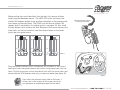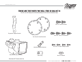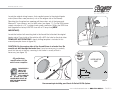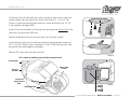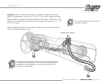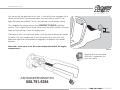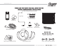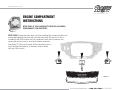
1
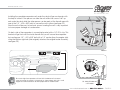
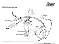
PERFECT
FIT
S E R I E S
Elite
©
Installation Manual
1967-1968 Mustang
DOCUMENT #1-2026
©2011 ClassicAutoAir / 6.11vs1
©
Congratulations...
You have just purchased the highest quality, best performing
A/C system ever designed for your Classic Vehicle.
To obtain the high level of performance and dependability our systems are known for, please pay close attention to the
following instructions. Our installation steps and procedures are derived from a long history of research and
development and the combined experience achieved thru thousands of successful installations (and feedback from
customers like you). Please remember that our #1 goal is that you’ll have a successful installation and a system that
performs at a very high level for many years to come.
Before starting, read the instructions carefully, from beginning to end, and follow the proper sequence. We’ve included a
general A/C overview and a safety and general checklist that you should read before starting your installation.
Again, thank you from our entire staff.
www.classicautoair.com • 888.791.6384
©2011 ClassicAutoAir / 6.11vs1
A Basic A/C Overview
OUTSIDE AIR
1
Evaporator with Blower Fan
2
Compressor The compressor pumps and circulates the refrigerant through the system.
3
Condenser The condenser is a heat exchanger mounted at the front of the vehicle. Heat drawn out of the interior of
In order to remove the heat from the air in the vehicle, the A/C
evaporator allows the refrigerant to absorb the heat from the air passing over it. The blower fan moves cool air out into the car
interior.
Suction
Valve Discharge
Valve
the car is expelled here.
4
Receiver/Drier The drier not only dries refrigerant, it also filters the refrigerant and stores it under certain
Receiver
Drier
Condenser
Compressor
operating conditions.
5
High Pressure Switch A pressure switch is used to shut down the system if high or low pressure is
detected, basically it acts as a safety switch.
Firewall
Expansion Valve
AIR FROM INSIDE VEHICLE
1
SUC
LIQ
U
TIO
3
NH
OS
ID H
OS
E
2
GRO
POW
ER
UND
Evaporator Unit
OSE
GE H
R
A
H
DISC
COLD AIR INTO VEHICLE
5
4
E
The air conditioning system in your car is comprised of a compressor, condenser,
expansion valve, receiver/drier, and evaporator. Refrigerant (also known as Freon) is
compressed in the compressor and turns into a gas. In the condenser, this gas is cooled to a
liquid state and travels to the expansion valve. As the liquid refrigerant goes through the
expansion valve it rapidly cools in the evaporator. A fan blows over the evaporator and cools the
air that blows out your vents. The receiver-drier separates gas and liquid.
www.classicautoair.com • 888.791.6384 • OVERVIEW
©2011 ClassicAutoAir / 6.11vs1
Check List, Pre-Installation:
Before beginning the installation check the shipping box for the correct components. YOUR BOXED UNIT INCLUDES A LIST OF
MAJOR COMPONENTS AND A LIST OF BAGGED PARTS. We have a 5 stage check process to make sure you have everything you’ll
need.
If your vehicle has been or is being modified, some procedures will need to be adjusted to fit your particular application.
A basic cleaning of the engine compartment and interior before beginning will make things go more smoothly.
Check condition of engine mounts. Excessive engine movement can damage hoses to A/C and/or heater.
Before starting, check vehicle interior electrical functions (interior lights, radio, horn, etc). Make a note of anything that does not work as
it’s supposed to. During the installation you might find the opportunity to repair or upgrade non-working or out of date components.
When you’re ready to start the installation, DISCONNECT THE BATTERY FIRST.
Drain the radiator. Retain the coolant and reuse, or dispose of properly.
SAFETY FIRST: Wear eye protection while drilling/cutting, deburr sharp edges, and never get in a hurry or force a part.
Tools: Your installation only requires the basic tools everyone has in their garage, nothing exotic or specific to A/C or Heat equipment.
Procedures, During Installation:
Fittings: Use one or two drops of mineral oil (supplied with your kit) on ALL rubber o-rings, threads and rear of bump for o-ring where
female nut rides. Do not use thread tape or sealants.
Measure twice (or more), cut once
Should you have any technical questions, or feel you have defective components (or missing items), call us immediately,
we will be glad to assist you. Our toll-free number is listed on every page, we’re here to help!
YOU CAN NOW BEGIN THE INSTALLATION...
www.classicautoair.com • 888.791.6384 • CHECK LIST
©2011 ClassicAutoAir / 6.11vs1
Control & Operating Instructions
Your new Perfect Fit-Elite system offers complete comfort capabilities in
virtually every driving condition. This includes temperature control in all of the
modes. This system also provides the ability to blend the air between Face,
Heat, and Defrost modes simultaneously. To illustrate the various ways you can
adjust the airflow direction and temperature - we’ve provided these handy
illustrations and chart to show exactly how you can adjust your Perfect
Fit-Elite for maximum comfort...
FIT
Elite
FACE
S E R I E S
The FAN switch works like the OEM switch, the
far left position is OFF (all power to the system
is OFF in this position)
TEMP LEVER
OFF
There are 11
levels of
adjustment
within the
range of the
DASH/FLOOR
lever
1
2
3
4
5
6
7
8
9
10
11
DASH
HI
The
COLD/HOT
positions
works like
any
traditional
adjustment
lever
DEF
FLR
Compressor
State
Left Lever Postion
Distribution
1
Face A/C
100%
2
Face A/C
Defrost
80%
20%
3
Face A/C
Defrost
60%
40%
4
Face A/C
Defrost
40%
60%
5
Face A/C
Defrost
20%
80%
6
Defrost
100%
7
Floor
Defrost
20%
80%
8
Floor
Defrost
40%
60%
9
Floor
Defrost
60%
40%
10
Floor
Defrost
80%
20%
11
Floor
100%
ON
COLD
DEF
Unused
HOT
NOTE: When the TEMP lever is in the "FULL
COLD" position (TOP), the compressor is ON, no
matter what position the MODE lever is in (think
of it as a compressor-override function)
FLOOR
FAN SWITCH
MODE LEVER
PERFECT
ON
www.classicautoair.com • 888.791.6384 • PAGE 1
©2011 ClassicAutoAir / 6.11vs1
INTERIOR
COMPARTMENT
Remove Glovebox, Console (if
equipped) Radio and Bezel, and set
them aside for reinstall later
(see figure 1).
The removal of the Original Heater Assembly can be
accomplished by disconnecting three control cables. One is
attached to the Heat/Defrost door (see figure 2). One is
attached to the Temperature door, and one is attached to the
Vent / Heat door (see figure 3). Disconnect the electrical
harness from the assembly. Also remove attachment screw
located in front of the air inlet (see figure 4).
FIGURE 1
When retaining parts it’s a
good idea to store parts in a
zip lock bag, labeled with
info where the parts came
EA
ID
GOOD
from and what size/type of
tool is needed to reinstall. Cleaning
the parts before you need to reinstall
them is a good idea too.
FIGURE 2
FIGURE 3
FIGURE 4
www.classicautoair.com • 888.791.6384 • PAGE 2
©2011 ClassicAutoAir / 6.11vs1
Locate blower motor on the firewall (Passenger Side) in the engine
compartment. Remove all 4 nuts around blower. Also disconnect the electrical
connector from the blower motor (see figure 5A). Cut wires at grommet in
firewall.
B
1"
ER
AT
E
OS E
R H HOS
HE
E
AT
ER
HE
LOW
ER
Located on the drivers side lower dash is a fresh air vent assembly. Remove this
unit and set aside (it will not be reinstalled, see figure 7, and NOTE below).
ER
OW OR
BL OT
M
UPP
DRAIN COOLANT FROM RADIATOR and store safely to reuse or recycle
accordingly. Cut heater hose approximately 1” from firewall (see figure 5B). Also,
to prevent forgetting to refill the coolant when the installation is completed, do
not put the cap back into place - intead put the cap to the side and cover
radiator hole with a clean rag or something similar (this will help prevent you
from starting the engine without coolant at the end of the installation).
A
FIGURE 5
OEM Heater Unit
(Not reinstalled)
FIGURE 6
FIGURE 7
TECH TIPS
Over time the nuts that hold the OEM fresh air vent assembly
may have become rusty or fused to the studs. Use a good
quality penetrating spray to help the process of removing the
nuts and don’t over-stress the studs.
www.classicautoair.com • 888.791.6384 • PAGE 3
©2011 ClassicAutoAir / 6.11vs1
THESE ARE THE PARTS YOU WILL FIND IN BAG KIT A
You will use all of these parts and hardware during the next series of installation steps.
Pressure Switch
(engine compartment)
Ground
Ground
Ground
ECU
Thermostat
OEM Power
Supply
Cables
Fan
Plug
Wire Harness Power Supply
Blower Switch
Connection
Cable Integrators
Two #8 - 20x3/8" Screws
Relay
Two - Cable Clips
Blower Switch Knob
Blower Switch Bracket
Blower Switch
Two #6 - 20x3/8" Screws
NOTE: Illustrations NOT shown actual size
www.classicautoair.com • 888.791.6384 • PAGE 4
©2011 ClassicAutoAir / 6.11vs1
Remove The Heater Control Head From The Dash.
1) There are four OEM screws that hold your control head to the dash, two on
the lower side and two on the upper. Remove and retain these screws. Remove
the control head assembly (see figure 8).
2) Remove the OEM blower switch knob. Retain the screw, you will use it again
shortly. Remove the control cables and the original blower switch and set aside
(these will not be reused, see figure 9).
3) Attach the new blower switch with bracket to the top part of the back of the
face plate (see figure 10), utilizing the OEM screw and into the bracket pedestal
with the two supplied #6 - 20x3/8" screws.
FIGURE 8
#6 - 20x3/8" Screws
(OEM switch
not reinstalled)
OEM Screw
Retain all the OEM parts that
you remove, at least until the
installation is completed.
GOOD IDEA
FIGURE 9
FIGURE 10
www.classicautoair.com • 888.791.6384 • PAGE 5
©2011 ClassicAutoAir / 6.11vs1
Attaching our exclusive
cables to the
control head is accomplished in three easy
steps: Step 1) place the loop ends of our new
cables around the appropriate lever ends (as
shown in figure 11) then, Step 2) attach the
cables to the OEM control head base with
the OEM screws you removed earlier, utilizing
the supplied cable clamps (see figure 12).
Our new cables will fit into the grooves on the
OEM control head base once you install the
supplied cable clamps (see figure 13).
FIGURE 12
OEM Screws
OEM control head base
FIGURE 11
FIGURE 13
NOTE: The clips will match and fit into the
curved outer grooves of your
OEM attachment pedestal
www.classicautoair.com • 888.791.6384 • PAGE 6
©2011 ClassicAutoAir / 6.11vs1
Step 3) We included our exclusive
cable Integrators, which you will now
attach to the new cables using the two #8 - 20x3/8" screws. Attach them
exactly as shown with the integrator marked "MODE" (it has Yellow, Blue, Green
wires) on the left-hand side and the other integrator labeled
"TEMP" (Brown, Purple, and White wires) on the right-hand
side (see figure 14). Route the extended wires from the
cables onto the posts on the integrators. The center lever is
left unused.
TEMP
MOD
E Co
Contr
ol
ntro
l
FIGURE 14
www.classicautoair.com • 888.791.6384 • PAGE 7
©2011 ClassicAutoAir / 6.11vs1
Before putting the control head back into the dash, first remove all three
knobs using an allenhead wrench. The HEAT/DEF knobs will need to be
rotated 180 degrees (upside down) and then reinstalled on the opposite side
from where you removed them. The TEMP knob will also be rotated 180
degrees (but it’s reinstalled in it’s original position, see figure 15). Also install
the new blower switch knob at this time. Because of the curved nature of the
lower dash, you will not be able to see the indicator letters on the knobs
(which are now upside down).
COLD
DASH
OFF
HI
COLD
DASH
DEF
DEF
DEF
TEMP
TEMP
HEAT
HOT
FLR
COLD
DASH
DEF
DEF
FLR
HI
DEF
HEAT
OFF
HOT
FLR
TEMP
HI
HEAT
OFF
Plug the blower switch connector
into the new control switch
HOT
FIGURE 15
Plug the harness blower switch connection into the back of the control
head and insert the entire harness and switch component back into the
dash. Position the entire control head back flush with the lower dash and
secure with the OEM retainers and nuts you removed earlier (see figure 16).
FIGURE 16
QUICK
NOTE
Even without the indicators being visible on the knobs, it
will only take a short amount of time to get used to the
new procedure for controlling temperature and airflow.
www.classicautoair.com • 888.791.6384 • PAGE 8
©2011 ClassicAutoAir / 6.11vs1
THESE ARE THE PARTS YOU WILL FIND IN BAG KIT B
You will use all of these parts and hardware during the next series of installation steps.
Two 1/4 - #20 x 5/8" Bolts
Evaporator Support Bracket
Four #10 - 16 x 3/4" Tek Screws
Two Fresh Air Inlet Block Offs
One Male Spade Connector
Defrost/Heat Duct Assembly
One J-Clip
Four #10 - 10 x 5/8" Phillips Screws
One 1/2" Washer
Illustrations NOT shown actual size
www.classicautoair.com • 888.791.6384 • PAGE 9
©2011 ClassicAutoAir / 6.11vs1
Locate the original wiring harness that supplied power to the original heater
motor (these wires were previously cut on the engine side of the firewall).
Reaching thru the glove box opening pull these wires out of their grommet.
Measure 4” from harness and cut both wires (see figure 17). On the OEM power
supply wire attach a 1/4” insulated male spade connector. Within the OEM fuse
box upgrade the factory HEATER fuse with a 20 amp fuse (VERY
IMPORTANT).
4"
Locate the bottom left mounting hole in the firewall that attached the original
heater motor. From inside of the vehicle drill a 5/8" dia. hole for the drain tube.
TEMPLATE NOTIFICATION! A handy drilling template is included in this
manual (example shown in figure 18).
CAUTION: On the engine side of the firewall there is a brake line. Be
careful not drill through the brake line. It may be necessary to carefully
push this line out of the way, securing it a bit lower is usually all that is
necessary (see figure 19)
FIGURE 17
THIS IS
FROM THE
INSIDE
OF THE
CAR!
All preliminary
modifications to the
vehicle are complete.
YOU CAN DRILL A
SMALL PILOT
HOLE IN THIS
LOCATION FIRST
TECH TIPS
WITH A SMALLER
DRILL BIT (LIKE 3/16"), THEN
PROCEED WITH THE 5/8" BIT
ONCE YOU KNOW YOU HAVE
CLEAR SPACE.
HEATER MOTOR
HOLE
1 3/8"
E
!
ION
INE
L
K
RA
5/8"
B
UT
CA
5/8" HOLE
FIGURE 19
FIGURE 18
You can now begin installing your Classic Air Perfect Fit Elite System.
www.classicautoair.com • 888.791.6384 • PAGE 10
©2011 ClassicAutoAir / 6.11vs1
Locate the Fresh Air inlet block off. Install over hole in inlet cowl as shown on
the passenger side (see figure 20A). Attach with three #10 - 16 x 3/4" Tek
Screws. Locate the mounting tab location as shown and attach the 1/4" 20
J-clip supplied (see figure 20B).
Install a Fresh Air inlet block off over the vent opening at the drivers-side in the
same way, using the four OEM nuts.
A
Remove evaporator unit from box and place on a flat work surface.
Locate defrost / heat duct assembly and attach to the evaporator using two
#10 - 10 x 5/8" Phillips screws (see figure 21). NOTE: Be sure that the s-clips
are pushed over rear flange on evaporator.
B
Remove ECU from main unit and set aside.
FIGURE 20
Take a minute to familiarize yourself with the evaporator unit:
Actuator Motor
Blower Motor
Bracket
Floor/Face
Vent Door
Evaporator
Support Bracket
Holes
Thermostat
FIGURE 21
Blower Motor Plug
www.classicautoair.com • 888.791.6384 • PAGE 11
©2011 ClassicAutoAir / 6.11vs1
DASH
FIREWALL
Installing the complete evaporator unit under the dash will go much easier with
the help of a friend. One person can take the unit within the car and “roll” up
and under the dash while the other person can be ready at the firewall area with
one of the 1/4" - #20 x 5/8" bolts to secure the unit in place (see figure 22).
Now the unit will be easy to level and secure. Leveling the unit is very important
to insure proper drainage of condensation.
On back side of the evaporator is a mounting bracket with a 1/4"-20 J-clip. This
bracket will go flush with the inside firewall and you will secure the evaporator
by inserting one 1/4" - #20 x 5/8" bolt with a 1/4” washer (from the engine side)
using the bottom right hole (that originally attached the original heater assembly,
see figure 23).
FIGURE 22
LEVEL
TECH TIPS
Be sure to align the evaporator unit level with the bottom of instrument
panel (assuming the vehicle is sitting level) as shown above, but with a small
degree of tilt toward the back to allow proper drain of condensation.
FIGURE 23
1/4 - #20 x 5/8" bolts and
a 1/4” washer
www.classicautoair.com • 888.791.6384 • PAGE 12
©2011 ClassicAutoAir / 6.11vs1
The second 1/4 - #20 x 5/8" bolt attaches the blower motor mounting
bracket in the same location as the original heater mounting in front of the Air
Inlet. The blower support bracket will have an additional hole behind the 1/4 #20 x 5/8" Bolts. Install a #10 - 16 x 3/4" Tek screw through this hole and into
the cowling (see figure 24).
Locate in the Hardware Sack Kit the UPPER MOUNTING BRACKET and
attach to evaporator unit using two #10 - 10 x 5/8" Phillips screws. Attach
other end to the cowling with a #10 - 16 x 3/4" Tek Screw (see figure 25).
IMPORTANT NOTE: On the side of the main unit you will see several
holes for mounting holes... ONLY USE THE ONES ON THE FAR LEFT
FOR THIS BRACKET! Do not tap into the other holes for any reason (see
figure 26). Also, use a screwdriver and hand-power and do not over-tighten
so you don't strip the holes.
FIGURE 24
#10 - 16 x 3/4" Tek Screw
YES
FIGURE 26
NO!
NO!
FIGURE 25
#10 x 5/8"
Screws
www.classicautoair.com • 888.791.6384 • PAGE 13
©2011 ClassicAutoAir / 6.11vs1
THESE ARE THE PARTS YOU WILL FIND IN BAG KIT C
You will use all of these parts and hardware during the next series of installation steps.
Clear Plastic Drain Tube
Electronic Water Control Valve
Two 1" Cap Plugs
Six Worm Gear Clamps
Firewall Block Off
Two #10 - 16 x 3/4" Tek Screws
Refrigerant Tape
Illustrations NOT shown actual size
www.classicautoair.com • 888.791.6384 • PAGE 14
©2011 ClassicAutoAir / 6.11vs1
Hose connects to this connection
In Bag Kit C you’ll find the firewall block off. Install this over the hose
connections coming thru the firewall within the engine compartment. Attach with
two #10 - 16 x 3/4" Tek screws (Figure 27).
Seal around the tubes with the included refrigerant tape. This will keep
unwanted moisture and debris from entering thru the firewall... so seal carefully
and thoroughly.
IMPORTANT NOTICE
Classic Auto Air has done extensive testing on the
correct method to install the water valve in order to get a repeatable and
progressive temperature control. The water valve must be installed per these
FIGURE 27
instructions!....
COR
E
Connect one end to the upper connection on the upper tube
coming thru the block off assembly, and the other end to the
back side of the water valve (the electronic water valve is
labeled for easy installation).
Insert a 6" piece of the clear, 1/2" drain tube we included through the hole
previously drilled and attach over the drain nipple (see figure 28). Seal around
tube with refrigerant tape
ER
PU
MP
ER
Locate the upper connection from the evaporator/heater unit off
AT
HE
of the firewall and attach a 6” piece of 5/8” dia. heater hose with the
supplied worm gear clamp. Attach the inlet side of the water valve using
another supplied hose clamp. Attach a heater hose from the outlet side of the
electronic water valve and route to the connection on the water pump. Next run
another 5/8" heater hose from the bottom heater outlet and secure using a
worm gear clamp, and the other end to the intake connection on the water
pump, also with a worm gear clamp.
T
WA
FIGURE 28
1/2" Clear Drain Tube
Refrigerant Tape
www.classicautoair.com • 888.791.6384 • PAGE 15
©2011 ClassicAutoAir / 6.11vs1
THESE ARE THE PARTS YOU WILL FIND IN BAG KIT D
You will use all of these parts and hardware during the next series of installation steps.
ROL
CONT
VALVE
WATER
The ECU will be attached for shipping purposes to the body of the
main unit. You will need to detach and mount
elsewhere during
the next stage.
LOOR
FACE/F
ST
DEFRO
POWER
Five #10 - 16 x 3/4" Tek Screws
Yellow
Orange
Blue
Wire Harness System
Illustrations NOT shown actual size
www.classicautoair.com • 888.791.6384 • PAGE 16
©2011 ClassicAutoAir / 6.11vs1
We’ve included enough wire length to allow you to mount the ECU in a variety
of places. It is very important that you mount this in a place where it will stay dry
and that vibration is at a minimum. Also make sure that where ever you mount it
does not interfere with any moving controls or cables. We recommend
mounting it just above the right hand side of the main unit using the included
tek-screws. IMPORTANT! DON’T MOUNT THE ECU PERMANENTLY JUST
YET. THAT CAN BE DONE AFTER YOU CALIBRATE THE UNIT (SEE
NEXT PAGE).
In Bag Kit D you will find three wiring harnesses with connections at each end.
Plug the harness with YELLOW band into the YELLOW ECU port and the other
end into the servo motor on the main unit (motor is marked with YELLOW
INDICATOR). Repeat this process for the other two harnesses, following the
color coding indicated on cables and ports. Attach cable in the engine
compartment to the electronic water valve (see figure 29). Using one of the CAP
PLUGS provided, slot it and install over the heater hose/cable.
INSTALL (2)
1” dia. CAP PLUGS
OVER HOLES.
SLOT ONE FOR THE CABLE.
FIGURE 29
RO
CONT
L
LOOR
FACE/F
DEFRO
FIREWALL
VALVE
WATER
NOTE: The GREEN harness connection will be made from the harness you
previously installed, just plug the loose connection in the CONTROL
port on the ECU.
ST
POWER
www.classicautoair.com • 888.791.6384 • PAGE 17
©2011 ClassicAutoAir / 6.11vs1
Orang
eH
arn
e
Wiring Diagram/Overview
To 12V Power Supply
Re
Electronic Water Valve
d
/W
ss
hite
Wi
re
Compressor
r
G
Wh
Pressure Switch
Ground
Wire
ite
Blower Switch
s
ire
W
e
Blu
ess
arn
H
n
ee
ECU
Y e ll o w H a
Relay
Servo for Defrost Ducts
Blu
eW
ire
Thermostat
Red Wire
ss
ire
W
Blu
e
rne
Servo for Face/Floor Ducts
Blue Har
ness
Cable Integrators
Ground
Evaporator
Bl
ue
W ir e
Ground
REMINDER: BE SURE THAT THE WIRING HARNESS DOES NOT INTERFERE WITH THE OPERATION OF ANY CONTROLS.
www.classicautoair.com • 888.791.6384 • PAGE 18
©2011 ClassicAutoAir / 6.11vs1
TEMPORARILY RECONNECT THE BATTERY AT THIS TIME.
A
OFF
YOU CAN NOW CALIBRATE YOUR UNIT.
DEF
CALIBRATION: Before we boxed and shipped your unit, we tested and
calibrated it to factory specifications to make sure it is capable of operating at
maximum efficiency. However, the unit must still be calibrated to your specific
vehicle and controls. This is an easy process that will only take a few minutes.
ER
WAT
lib
Ca
ST
RO
DEF
L
RO
NT
CO
LO
E /F
FAC
OR
R
WE
PO
lib
Ca
QUICK
NOTE
rati
COLD
FLR
OFF
DASH
HI
COLD
DEF
HOT
FLR
HOT
4)
5)
Insert Calibration Key
Move MODE control to low extreme (FLOOR) and
TEMP control to high extreme (COLD)
Power Up Board (turn fan control to MEDIUM) the
LED comes ON
After 1 second the LED turns OFF
After 1 second the LED turns ON
B
6)
7)
8)
Move MODE control to other extreme (DASH)
After 1 second the LED turns OFF
After 1 second the LED turns ON
C
9) Move TEMP control to other extreme (HOT)
10) After 1 second the LED turns OFF
11) After 1 second the LED turns ON
3)
ST
RO
DEF
OR
O
/FL
E
FAC
L
RO
NT
CO
HI
VE
VAL
y
Ke
on
rati
HOT
1)
2)
A
VE
VAL
OFF
DASH
DEF
FLR
As you follow thru these steps you’ll be able to hear the motors working on your
unit. If for any reason your unit does not calibrate properly the first time, just turn
off the unit and rerun the setup process.
ER
WAT
HI
COLD
DASH
C
B
R
WE
PO
y
Ke
on
Disconnecting the power (i.e. battery) will not cause your ECU to
lose it’s settings. AFTER CALIBRATING, REMOVE KEY AND
STORE IN A SAFE, DRY PLACE - ALONG WITH THIS PAGE.
12) The motor calibration starts, one way
then the other, then the doors set
to midpoint
13) LED turns OFF
14) Turn power to OFF
15) Remove and store calibration key
www.classicautoair.com • 888.791.6384 • PAGE 19
©2011 ClassicAutoAir / 6.11vs1
THESE ARE THE PARTS YOU WILL FIND IN BAG KITS E, F, and G
You will use all of these parts and hardware during the next series of installation steps.
Bag E
Bag F
Bag G
Two Defrost Adaptor Reducers
Driver & Passenger Side Louver Ball Assemblies
Center Dash Vent
Two Duct Hoses, 2" I.D.
Two Duct Hoses, 2" I.D.
Face/Floor Assembly
Two Duct Hoses, 2" I.D.
Four Zip-Ties
Four #10 - 16 x 3/4" Tek Screws
Four Zip-Ties
Four Zip-Ties
Illustrations NOT shown actual size
www.classicautoair.com • 888.791.6384 • PAGE 20
©2011 ClassicAutoAir / 6.11vs1
Bag Kit E. The following steps are for left and right Defrost Diffusers...
Locate and route the duct hoses from the defrost/heat duct assembly upward
toward the OEM defrost vent, using the included defrost adaptor reducers to
make connection. Attach the flex hose to the defrost defuser adaptors using
zip-ties. Push adaptors onto defusers from below. The other end of the duct
hose is installed over the defrost/heat duct assembly outlets on main unit (see
figures 30 and 31).
The face/floor assembly comes preinstalled with s-clips which allow you to
install it onto the evaporator unit quickly and securely (see figure 32).
TOP OF DASH
OEM Defrost
Vent
Defrost Adaptor
Reducer
FIGURE 31
OEM Defrost Vent
S-clips (already installed)
FIGURE 30
Defrost Adaptor Defuser
Duct Hose
(Secured with zip-tie)
FIGURE 32
www.classicautoair.com • 888.791.6384 • PAGE 21
©2011 ClassicAutoAir / 6.11vs1
Bag Kit F: Attach a louver ball assembly to the bottom edge of instrument
panel as shown below. Use two #10 - 16 x 3/4" Tek screws through the louver
ball assembly (be careful not to strip the head of the screws). Repeat the same
process for the louver ball assembly on the passenger side using two #10 - 16
x 3/4" Tek screws.
The smoother the route of the flex hoses
the better the airflow.
GOOD IDEA
Route supplied flex hoses as shown below. Take your time and route them so
they don’t become kinked or torn.
To defrost defuser adaptors
TECH TIPS
During installation of the hoses be aware of the eventual movement
of the wiper arm components. Also, the process for installing the
center louver vent will require a small amount of cutting. This is
outlined on the next page.
www.classicautoair.com • 888.791.6384 • PAGE 22
©2011 ClassicAutoAir / 6.11vs1
Bag Kit G: Installing the center louver vent requires a small amount of cutting to the dash support. Using a 3/8” socket reach to the
backside of the dash and remove ALL the nuts holding the trim bezel in place (see figure 33). In the center of the dash above where the
radio was, is a removeable plate. First, carefully remove the “A/C delete“ face off the dash (this will not reused).
In order for your new center louver fit to fit into the dash, some metal must be removed from the dash support area that is behind the trim
plate you removed, as indicated by the dotted lines in figure 34. The center support and about 1/4” of inch from the left and right sides
will need to be removed. We recommend removing a bit of the left and right side metal a bit at a time (a file is handy for this), using the
new center louver to test the opening. Once the
opening is large enough to fit the louver, you can install
it by first setting the left side of the louver into the
opening and aligning the tabs on the louver with the
posts on the backside of the dash trim (drivers side).
Then press the entire louver into place (which will be
held fully in place when you reinstall the passenger-side
trim). You can now attach the two flex hoses to the
back of the louver, (see figure 34). Secure the hoses
with the included zip-ties.
FIGURE 33
The louver is firmly held into place by the trim panels,
so once the trim panel is reinstalled this part of the
dash modification will be completed.
FIGURE 34
Approx.
1/4”
AFTER
MEASURE
TWICE.
CUT ONCE!
Approx.
1/4”
BEFORE
www.classicautoair.com • 888.791.6384 • PAGE 23
©2011 ClassicAutoAir / 6.11vs1
You can reinstall the glove box at this time. If your vehicle was equipped with a
center console (which you removed earlier), you may need to modify it (see
figure 36) before reinstallation. Test fit your particular console before cutting.
3"
This completes the interior portion of the PERFECT FIT-ELITE installation
process. This is a good time to make a final check that all the controls still move
freely and that nothing is loose or hanging down.
1 1/4"
REMOVE
The interior of your car should look pretty much the same as before you started
(or better). Plus you probably got to know the underside of your dash a lot
better and might even have repaired or upgraded components that needed
attention.
Good Job... Let's move on to the major components within the engine
compartment....
FIGURE 36
GOOD IDEA
Retaining all the non-resintalled
OEM parts is a good idea, but
that’s your choice.
If you have any questions before you move
on the final phase of this installation, call us.
888.791.6384
www.classicautoair.com • 888.791.6384 • PAGE 24
©2011 ClassicAutoAir / 6.11vs1
THESE ARE THE PARTS YOU WILL NEED FOR THE
ENGINE COMPARTMENT INSTALLATION
You’ll find all of these parts within the main box
A
Liquid Tube
B
Condenser Brackets
Drier
Drier Bracket
Condenser
Splice and
Bullet Connector
Pressure Switch
/16" Liquid Hose
#6 5
Four Zip-Ties
uc
#10 1
Bag of O-rings and Mineral Oil Tube
ti o
3 /3
81
#
Eight #10 - 20x5/8" Screws
nH
ose
2" D
ischa
rge Hos
e
Pressure Switch Harness
Three Refrigerant Hoses
/2"
S
Two #8 - 20 x 5/8" Bolts and Lock Nuts
www.classicautoair.com • 888.791.6384 • PAGE 25
©2011 ClassicAutoAir / 6.11vs1
ENGINE COMPARTMENT
INSTRUCTIONS
ENGINE
COMPARTMENT
STEP ONE: IF YOU HAVE NOT DONE SO ALREADY,
DISCONNECT THE BATTERY.
STEP TWO: During the next steps you’ll be installing the condenser, drier, and
routing the high/low pressure lines and the liquid line. Since much of this is
installed in the OEM location for the condenser, you’ll need to remove the
center grill section, horn(s), and latch support assembly
(see figure 37). Be sure to retain all the mounting screws –
you’ll reinstall these pieces in the exact reverse order
with the OEM screws.
FIGURE 37
www.classicautoair.com • 888.791.6384 • PAGE 26
©2011 ClassicAutoAir / 6.11vs1
STEP THREE: DRIER AND CONDENSER PREPARATION. You can perform
most of the following steps on a clean flat surface like a workbench. Lay the
condenser down so that both hose connections are on the right side (the larger
connection will be on top). The drier is conveniently mounted on the right hand
side of the condenser. First insert the drier into the drier mounting bracket (it’s
basically a sleeve for the drier). Attach the drier liquid tube to the drier and also
to the connection on the condenser (tighten connections at
either end using supplied o-rings on both ends and a few
Brackets angles outward
drops of mineral oil to each o-ring). With these two
components combined it will easy to find the correct place to
attach the drier bracket to the condenser with the included
#8-20 x 5/8” bolts and lock nuts (attach drier and bracket
4th, 5th Holes
from the back of the condenser).
TECH TIPS
You can easily find the
correct position for mounting
the drier to the condenser by
using the drier liquid tube as
a gauge.
A
Four #10-5/8" screws
8th, 9th Holes
STEP FOUR: Screw the high-pressure switch into the port at
the lower end of the drier liquid tube. Go ahead and plug the
pressure switch harness into the switch at this time (black
electrical boot with two long white wires).
STEP FIVE: Install the upper condenser bracket (A) using
four #10 - 20 x 5/8“ screws in the 4th, 5th, 8th and 9th holes
on the condenser from the left, be sure the bend on the
bracket is facing towards you. Next, attach the lower bracket
(B) using four #10-20 x 5/8” screws in the 5th, 6th, 9th and
10th hole from the left hand side. This bracket has a large
hole that corresponds to the OEM latch support previously
removed from the vehicle.
5th, 6th Holes
TECH TIPS
Reminder...
Use two
wrenches to
tighten o-ring
fittings
9th, 10th Holes
Four #10-5/8" screws
B
www.classicautoair.com • 888.791.6384 • PAGE 27
©2011 ClassicAutoAir / 6.11vs1
STEP SIX: Your OEM radiator support was designed to support a A/C
condenser and conveniently has two small indentations on the drivers side core
support (see figure 38, aftermarket core supports may or may not have these
indentations). Locate these two small indentations and drill a 1 3/8” hole thru
each (be sure to check for any obstructions before drilling, and remove any sharp
burrs from the drilling before continuing, see figure 38), then the area between the
two holes will be easy to remove (example figure 39). You’ll route the discharge
hose to the compressor will go thru this hole, as well as the liquid hose and the
wiring harness plug for the high-pressure switch.
MEASURE
TWICE.
CUT ONCE!
STEP SEVEN: Place the condenser/drier unit into place, locating it so that the
holes in the condenser brackets align with the holes in the core support used to
attach the hood latch (it will rest on the lower radiator core brace, see figure 40).
FIGURE 38
If you want to verify that you
have the correct indentations in sight before drilling,
TECH TIPS place fit the condenser into
it’s final location. Also, the
holes on the upper bracket are
larger than needed to allow for small
adjustments. The condenser is held in
place when the hood latch is
reinstalled at a later time.
Drill two 1 3/8" holes
FIGURE 39
FIGURE 40
www.classicautoair.com • 888.791.6384 • PAGE 28
©2011 ClassicAutoAir / 6.11vs1
tru
rS
de
Fe
n
CO
COMMPLETE
PRES
KIT SOR
ts
STEP EIGHT: Time to install the compressor kit. Included in your box is a
premium compressor kit with all the parts you’ll need to install the compressor.
This kit includes instructions specifically written for your engine. Once you’ve
installed the complete compressor kit, continue on to connecting the hoses.
FIGURE 41
STEP NINE: CONNECTING THE HOSES:
1) Attach the #8 Discharge Hose (13/32") to the upper connection of the
condenser and route thru the hole previously drilled in the core support and route
to the compressor. Tighten fittings using o-rings and mineral oil provided.
2) Attach the #6 liquid hose (5/16") to the drier and route thru the remaining hole
previously drilled into the core support and along the underside of the fender
struts, around the engine, and to the connection at the firewall on the evaporator
unit (see figure 41). Using supplied zip-ties you’ll attach this hose, the suction
hose and the lead from the high pressure switch to the strut braces, securing all
three at once. Tighten fittings using o-rings and mineral oil supplied in kit.
3) Attach the #10 suction hose (1/2”) to the compressor and route as mentioned
above. Tighten fittings using o-rings and mineral oil supplied in the kit.
www.classicautoair.com • 888.791.6384 • PAGE 29
©2011 ClassicAutoAir / 6.11vs1
STEP TEN: Connect the pressure switch by first connecting one wire to the
connection on the compressor, and the other wire will be routed along with the
liquid hose along the underside of the fender supports and connected to the blue
lead you put thru the firewall during the interior installation (for attachment route,
see figure 41, on previous page). We’ve included a bullet and slice connector to
make these connections, use a crimp tool to secure these properly.
FINAL STEPS: You can now complete this portion of the installation by
reinstalling the grill, horns, and latch support in reverse order. NOTE: The OEM
screws for the hood latch support will hold your new condenser in place, so be
sure to fully tighten these during this step. Take a look around at your installation
and check all fittings and bolts for tightness, check the heater hose clamps for
tightness, and make sure nothing is routed in a way to obstruct any moving
parts. You can refill the radiator and reconnect the battery at this time.
WAY TO GO! You’ve just completed the installation of your new A/C system.
The very final step is to fully charge and test your new system.
On the next page you’ll find specifications for proper final preparation
for your A/C technician.
www.classicautoair.com • 888.791.6384 • PAGE 30
©2011 ClassicAutoAir / 6.11vs1
New A/C System Preparation
Centerline of the Oil Plug
Please read thru these procedures before completing this new A/C system charging
operation. A licensed A/C technician should be utilized for these procedures to insure that
your new system will perform at it’s peak, and that your compressor will not be damaged.
1) Your radiator/cooling system is an integral part of your new system. Please insure that you
have a 50/50 mix of distilled water and antifreeze. The heater coil MUST be purged
(cycle heater control valve) to make sure no water, without antifreeze, is in the heater coil
before you charge the A/C system.
2) Evacuate the system for 45 minutes (minimum).
3) Your new compressor MUST be hand-turned 15-20 revolutions before and after
charging with liquid. Failure to do this may cause the reed valves to become damaged (this
damage is NOT covered by your warranty).
4) Your new system requires 134a refrigerant. It will require 1.5 lbs (or 24 oz).
5) Your new compressor comes charged with oil - NO additional oil is needed.
6) Insure that the new belt is tight.
7)
DO NOT CHARGE SYSTEM WITH LIQUID WHILE THE ENGINE IS RUNNING!
RECOMMENDED TEST CONDITIONS: (After system has been fully charged and tested for basic
operation)
• Determine the temperature outside of the car
• Connect gauges or service equipment to high/low charging ports
• Place blower fan switch on medium
• Close all doors and windows on vehicle
• Place shop fan directly in front of condenser
• Run engine idle up to approx. 1500 rpm
ACCEPTABLE OPERATING PRESSURE RANGES:
1. HIGH-SIDE PRESSURES (150-250 PSI)
2. LOW-SIDE PRESSURES (15-25 PSI in a steady state)
90˚
90˚
CAUTION! When mounting your compressor
and/or adjusting the belt, use caution not to tilt the
compressor up to or more than 90˚ off the
centerline of the oil fill plug. This can cause
compressor failure.
Do not tilt, shake or turn
refrigerant can upside-down
OR use a charging station to
install refrigerant while the
engine is running. Doing so will
direct liquid refrigerant into the
compressor piston chamber, causing damage to
reed valves and/or pistons and/or other components, as
well as potentially seizing the compressor. Allow a
minimum of 30 minutes for liquid to "boil off.” You must
hand turn the compressor hub (not the pulley) a minimum
of 15 complete revolutions prior to starting the engine
with the clutch engaged.
Readings above are based on an ambient temperature of 90˚ with an adequate airflow on condenser
www.classicautoair.com • 888.791.6384 • PREP