1
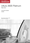
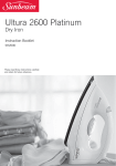
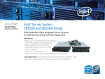
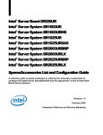
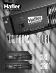
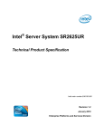
Basic Rail Kit Install Guide for
Intel® Server Chassis
A Guide for Technically Qualified Assemblers of Intel® Identified Subassemblies/
Products
Intel® Server Chassis SR1500
Intel® Server Chassis SR1550
Intel® Server Chassis SR1600
Intel® Server Chassis SR1625
Intel® Server Chassis SR2400
Intel® Server Chassis SR2500
Intel® Server Chassis SR2600
Intel® Server Chassis SR2625
Intel® Server System SR1560SF
Intel Order Number: D59599-003, Rev. 02
Disclaimer
Information in this document is provided in connection with Intel® products. No license, express or implied, by
estoppel or otherwise, to any intellectual property rights is granted by this document. Except as provided in Intel's
Terms and Conditions of Sale for such products, Intel assumes no liability whatsoever, and Intel disclaims any
express or implied warranty, relating to sale and/or use of Intel® products including liability or warranties relating to
fitness for a particular purpose, merchantability, or infringement of any patent, copyright or other intellectual property
right. Intel products are not designed, intended or authorized for use in any medical, life saving, or life sustaining
applications or for any other application in which the failure of the Intel product could create a situation where
personal injury or death may occur. Intel may make changes to specifications and product descriptions at any time,
without notice.
Intel® server boards contain a number of high-density VLSI and power delivery components that need adequate
airflow for cooling. Intel's own chassis are designed and tested to meet the intended thermal requirements of these
components when the fully integrated system is used together. It is the responsibility of the system integrator that
chooses not to use Intel developed server building blocks to consult vendor datasheets and operating parameters to
determine the amount of airflow required for their specific application and environmental conditions. Intel
Corporation can not be held responsible if components fail or the server board does not operate correctly when used
outside any of their published operating or non-operating limits.
Intel, Intel Pentium, and Intel Xeon are trademarks or registered trademarks of Intel Corporation or its subsidiaries in
the United States and other countries.
* Other names and brands may be claimed as the property of others.
Copyright © 2008, Intel Corporation. All Rights Reserved
ii
Basic Rail Kit Install Guide for Intel® Server Chassis
Safety Information
Important Safety Instructions
Read all caution and safety statements in this document before performing any of the
instructions. See also Intel Server Boards and Server Chassis Safety Information on the
Intel® Server Deployment Toolkit CD and/or at http://support.intel.com/support/
motherboards/server/sb/cs-010770.htm.
Wichtige Sicherheitshinweise
Lesen Sie zunächst sämtliche Warnund Sicherheitshinweise in diesem Dokument, bevor
Sie eine der Anweisungen ausführen. Beachten Sie hierzu auch die Sicherheitshinweise zu
Intel-Serverplatinen und Servergehäusen auf der Intel® Server Deployment Toolkit CD
oder unter http://support.intel.com/support/motherboards/server/sb/cs-010770.htm.
Consignes de sécurité
Lisez attention toutes les consignes de sécurité et les mises en garde indiquées dans ce
document avant de suivre toute instruction. Consultez Intel Server Boards and Server
Chassis Safety Information sur le Intel® Server Deployment Toolkit CD ou bien rendezvous sur le site http://support.intel.com/support/motherboards/server/sb/cs-010770.htm.
Instrucciones de seguridad importantes
Lea todas las declaraciones de seguridad y precaución de este documento antes de realizar
cualquiera de las instrucciones. Vea Intel Server Boards and Server Chassis Safety
Information en el Intel® Server Deployment Toolkit CD y/o en http://support.intel.com/
support/motherboards/server/sb/cs-010770.htm.
重要安全指导
Basic Rail Kit Install Guide for Intel® Server Chassis
iii
Safety Information
Warnings
Heed safety instructions: Before working with your server product, whether you are
using this guide or any other resource as a reference, pay close attention to the safety
instructions. You must adhere to the assembly instructions in this guide to ensure and
maintain compliance with existing product certifications and approvals. Use only the
described, regulated components specified in this guide. Use of other products /
components will void the UL listing and other regulatory approvals of the product and
will most likely result in noncompliance with product regulations in the region(s) in which
the product is sold.
System power on/off: The power button DOES NOT turn off the system AC power. To
remove power from system, you must unplug the AC power cord from the wall outlet.
Make sure the AC power cord is unplugged before you open the chassis, add, or remove
any components.
Hazardous conditions, devices and cables: Hazardous electrical conditions may be
present on power, telephone, and communication cables. Turn off the server and
disconnect the power cord, telecommunications systems, networks, and modems attached
to the server before opening it. Otherwise, personal injury or equipment damage can
result.
Electrostatic discharge (ESD) and ESD protection: ESD can damage disk drives,
boards, and other parts. We recommend that you perform all procedures in this chapter
only at an ESD workstation. If one is not available, provide some ESD protection by
wearing an antistatic wrist strap attached to chassis ground any unpainted metal surface on
your server when handling parts.
ESD and handling boards: Always handle boards carefully. They can be extremely
sensitive to ESD. Hold boards only by their edges. After removing a board from its
protective wrapper or from the server, place the board component side up on a grounded,
static free surface. Use a conductive foam pad if available but not the board wrapper. Do
not slide board over any surface.
Installing or removing jumpers: A jumper is a small plastic encased conductor that slips
over two jumper pins. Some jumpers have a small tab on top that you can grip with your
fingertips or with a pair of fine needle nosed pliers. If your jumpers do not have such a
tab, take care when using needle nosed pliers to remove or install a jumper; grip the
narrow sides of the jumper with the pliers, never the wide sides. Gripping the wide sides
can damage the contacts inside the jumper, causing intermittent problems with the
function controlled by that jumper. Take care to grip with, but not squeeze, the pliers or
other tool you use to remove a jumper, or you may bend or break the pins on the board.
iv
Basic Rail Kit Install Guide for Intel® Server Chassis
Contents
Contents
Safety Information ..................................................................................................... iii
Important Safety Instructions ................................................................................................ iii
Wichtige Sicherheitshinweise ............................................................................................... iii
Consignes de sécurité .......................................................................................................... iii
Instrucciones de seguridad importantes ............................................................................... iii
Rail Kit Installation Instructions ................................................................................ 1
Before You Begin ................................................................................................................... 1
Tools and Supplies Needed ........................................................................................................ 1
Kit Content List (AXXBASRAIL13) .............................................................................................. 2
Installation Instructions .......................................................................................................... 3
Remove the Inner Rail from the Rail Assembly .......................................................................... 3
Install Outer Rail Slides to Rack Posts ....................................................................................... 4
Attach Inner Rails to Server Chassis Sidewalls .......................................................................... 5
Install the Server Chassis into the Rack ..................................................................................... 6
Basic Rail Kit Install Guide for Intel® Server Chassis
v
Contents
vi
Basic Rail Kit Install Guide for Intel® Server Chassis
List of Figures
List of Figures
Figure 1. Rail Kit Components ................................................................................................... 2
Figure 2. Removing the Inner Rail from the Rail Assembly........................................................ 3
Figure 3. Installing the Outer Rail Slides to the Rack Posts....................................................... 4
Figure 4. Attaching the Inner Rails to the Server Chassis Sidewalls ......................................... 5
Figure 5. Installing the Server Chassis into the Rack................................................................. 6
Figure 6. Installing the Server Chassis into the Rack................................................................. 7
Basic Rail Kit Install Guide for Intel® Server Chassis
vii
List of Figures
viii
Basic Rail Kit Install Guide for Intel® Server Chassis
1
Rail Kit Installation Instructions
Use the instructions in this installation guide to install the AXXBASRAIL13 rail kit to
one of the following Intel® products:
•
•
•
•
•
•
•
•
•
Intel® Server Chassis SR1500
Intel® Server Chassis SR1550
Intel® Server Chassis SR1600
Intel® Server Chassis SR1625
Intel® Server Chassis SR2400
Intel® Server Chassis SR2500
Intel® Server Chassis SR2600
Intel® Server Chassis SR2625
Intel® Server System SR1560SF
Before You Begin
Before installing the rail kit, observe these safety guidelines:
1. Turn off all peripheral devices connected to the server.
2. Turn off the server by pressing the power button on the front of the chassis. Then
unplug the AC power cord(s) from the chassis or wall outlet.
3. Label and disconnect all peripheral cables and all telecommunications lines connected
to I/O connectors or ports on the back of the chassis.
4. Provide electrostatic discharge (ESD) protection by wearing an anti-static wrist strap
attached to a chassis ground - any unpainted metal surface - when handling
components.
Tools and Supplies Needed
• Phillips* (cross head) screwdriver (#1 bit and #2 bit)
• Anti-static wrist strap and conductive foam pad (recommended)
Basic Rail Kit Install Guide for Intel® Server Chassis
1
Rail Kit Installation Instructions
Kit Content List (AXXBASRAIL13)
Each Rack Mount Kit contains the following:
Note: The two included rail assemblies are NOT interchangeable. Each is installed into the rack
by its orientation (right or left) when standing in front of the rack. The right rail assembly
is identified with a BLUE (RH) sticker and the left rail assembly is identified with a
GREEN (LH) sticker.
Note: This kit includes two sets of 8-32x1/2” screws. One set of eight has a larger screw head
size than the second set of eight. Use the set of 8-32x1/2” screws that best fits the rack in
which the rail kit is being installed.
• Outer Rail Slide Assembly (2). See letter “A” in Figure 1.
• Inner Rail Slide (2). See letter “B” in Figure 1.
• Rail Safety Stop (one each on inner slides). See letter “C” in Figure 1.
• Outer Slide Rail Screws (8 #8-32 x 1/2). See letter “D” in Figure 1.
• Inner Slide Rail Screw (8 #6-32 x 1/4). See letter “D” in Figure 1.
• Rack Screws (2 #8-32 x 3/4). See letter “D” in Figure 1.
D
C
e
top
a
hS
lid
it
ew
er S
B
Inn
S
fety
le
tab
A
us
Adj
er
Out
Slid
AF000626
Figure 1. Rail Kit Components
2
Basic Rail Kit Install Guide for Intel® Server Chassis
Rail Kit Installation Instructions
Installation Instructions
Remove the Inner Rail from the Rail Assembly
1. Extend the inner rail until it locks. See letter “A” in Figure 2.
2. Depress the spring safety lock to release the inner rail. See letter “B” in Figure 2.
3. Remove the inner rail from the rail assembly. See letter “C” in Figure 2.
Figure 2. Removing the Inner Rail from the Rail Assembly
Basic Rail Kit Install Guide for Intel® Server Chassis
3
Rail Kit Installation Instructions
Install Outer Rail Slides to Rack Posts
1. Attach the outer rail slides to the rack posts using two #8-32 x 1/2 screws at the front
posts, and two #8-32 x 1/2 screws at the rear posts. See letter “A” in Figure 3.
Note: The rail flanges mount to the inside of each post.
ack
fR
ro
Rea
of
ont
k
Rac
Fr
AF000628
Figure 3. Installing the Outer Rail Slides to the Rack Posts
4
Basic Rail Kit Install Guide for Intel® Server Chassis
Rail Kit Installation Instructions
Attach Inner Rails to Server Chassis Sidewalls
1. Insert the inner rails over the server chassis sidewall studs. See letter “A” in Figure 4.
2. Slide the inner rails toward the front of the server chassis. See letter “B” in Figure 4.
3. Secure the inner rails with one #6-32 x 1/4 screw for each rail. See letter “C” in
Figure 4.
Figure 4. Attaching the Inner Rails to the Server Chassis Sidewalls
Basic Rail Kit Install Guide for Intel® Server Chassis
5
Rail Kit Installation Instructions
Install the Server Chassis into the Rack
1. Align the inner rails (attached to the server chassis) with the outer rail assemblies
(attached to the rack). See letter “A” in Figure 5.
Note: The inner slides must be positioned all the way forward in the rails to ensure proper
installation of the server.
2. Engage the matching rails and slide the server chassis into the rack (see letter “B” in
Figure 5) until the two safety stops lock into position (see letter “C” in Figure 5).
Figure 5. Installing the Server Chassis into the Rack
6
Basic Rail Kit Install Guide for Intel® Server Chassis
Rail Kit Installation Instructions
3. Depress the two safety locks (one on each side). See letter “A” in Figure 6.
4. Slide the server chassis all the way into the rack. See letter “B” in Figure 6.
5. Use the rack screws (#8-32 x 3/4) to secure the chassis and rack handles into the rack.
See letter “C” in Figure 6.
Figure 6. Installing the Server Chassis into the Rack
Basic Rail Kit Install Guide for Intel® Server Chassis
7
Rail Kit Installation Instructions
8
Basic Rail Kit Install Guide for Intel® Server Chassis