1
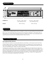
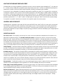
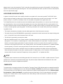
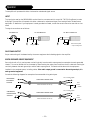
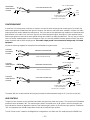
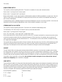
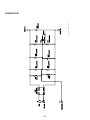
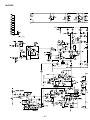
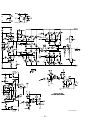
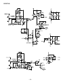
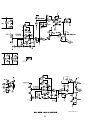
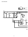
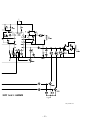
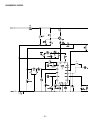
Owner’s Manual
SR2300
SR2600
Table of Contents
DECLARATION OF CONFORMITY . . . . . . . . . . . . . . . . . . . . . . . . . . . . . . . . . . . . . . . . . . . . . . . . . . . . . . . . . . . . . . 2
SAFETY INFORMATION . . . . . . . . . . . . . . . . . . . . . . . . . . . . . . . . . . . . . . . . . . . . . . . . . . . . . . . . . . . . . . . . . . . . . . .3
SPECIFICATIONS . . . . . . . . . . . . . . . . . . . . . . . . . . . . . . . . . . . . . . . . . . . . . . . . . . . . . . . . . . . . . . . . . . . . . . . . . . . 8
INTRODUCTION . . . . . . . . . . . . . . . . . . . . . . . . . . . . . . . . . . . . . . . . . . . . . . . . . . . . . . . . . . . . . . . . . . . . . . . . . . . .9
TECHNICAL DESIGN FEATURES . . . . . . . . . . . . . . . . . . . . . . . . . . . . . . . . . . . . . . . . . . . . . . . . . . . . . . . . . . . . . . . . .9
Why a new amplifier topology? . . . . . . . . . . . . . . . . . . . . . . . . . . . . . . . . . . . . . . . . . . . . . . . . . . . . . . . . . . . . . . .9
What else distinguishes these amplifiers? . . . . . . . . . . . . . . . . . . . . . . . . . . . . . . . . . . . . . . . . . . . . . . . . . . . . . . .10
Universal Line Voltage Input . . . . . . . . . . . . . . . . . . . . . . . . . . . . . . . . . . . . . . . . . . . . . . . . . . . . . . . . . . . . . . . .10
Protection Circuits . . . . . . . . . . . . . . . . . . . . . . . . . . . . . . . . . . . . . . . . . . . . . . . . . . . . . . . . . . . . . . . . . . . . . . .10
DESIGN FEATURES . . . . . . . . . . . . . . . . . . . . . . . . . . . . . . . . . . . . . . . . . . . . . . . . . . . . . . . . . . . . . . . . . . . . . . . . . 11
INSTALLATION . . . . . . . . . . . . . . . . . . . . . . . . . . . . . . . . . . . . . . . . . . . . . . . . . . . . . . . . . . . . . . . . . . . . . . . . . . . . 12
Cooling . . . . . . . . . . . . . . . . . . . . . . . . . . . . . . . . . . . . . . . . . . . . . . . . . . . . . . . . . . . . . . . . . . . . . . . . . . . . . . . 12
Power/Thermal Requirements . . . . . . . . . . . . . . . . . . . . . . . . . . . . . . . . . . . . . . . . . . . . . . . . . . . . . . . . . . . . . . .12
Noise . . . . . . . . . . . . . . . . . . . . . . . . . . . . . . . . . . . . . . . . . . . . . . . . . . . . . . . . . . . . . . . . . . . . . . . . . . . . . . . . .12
AC Line . . . . . . . . . . . . . . . . . . . . . . . . . . . . . . . . . . . . . . . . . . . . . . . . . . . . . . . . . . . . . . . . . . . . . . . . . . . . . . .12
Audio Ground Chassis/Float Switch . . . . . . . . . . . . . . . . . . . . . . . . . . . . . . . . . . . . . . . . . . . . . . . . . . . . . . . . . . .13
Output . . . . . . . . . . . . . . . . . . . . . . . . . . . . . . . . . . . . . . . . . . . . . . . . . . . . . . . . . . . . . . . . . . . . . . . . . . . . . . . .13
Power Switch . . . . . . . . . . . . . . . . . . . . . . . . . . . . . . . . . . . . . . . . . . . . . . . . . . . . . . . . . . . . . . . . . . . . . . . . . . .13
OPERATION . . . . . . . . . . . . . . . . . . . . . . . . . . . . . . . . . . . . . . . . . . . . . . . . . . . . . . . . . . . . . . . . . . . . . . . . . . . . . .14
Input . . . . . . . . . . . . . . . . . . . . . . . . . . . . . . . . . . . . . . . . . . . . . . . . . . . . . . . . . . . . . . . . . . . . . . . . . . . . . . . . . 14
Daisy Chain Output . . . . . . . . . . . . . . . . . . . . . . . . . . . . . . . . . . . . . . . . . . . . . . . . . . . . . . . . . . . . . . . . . . . . . .14
Earth Grounded Equipment . . . . . . . . . . . . . . . . . . . . . . . . . . . . . . . . . . . . . . . . . . . . . . . . . . . . . . . . . . . . . . . . .14
Floated Equipment . . . . . . . . . . . . . . . . . . . . . . . . . . . . . . . . . . . . . . . . . . . . . . . . . . . . . . . . . . . . . . . . . . . . . . .15
Level Controls . . . . . . . . . . . . . . . . . . . . . . . . . . . . . . . . . . . . . . . . . . . . . . . . . . . . . . . . . . . . . . . . . . . . . . . . . .15
Biamp/Stereo Switch . . . . . . . . . . . . . . . . . . . . . . . . . . . . . . . . . . . . . . . . . . . . . . . . . . . . . . . . . . . . . . . . . . . . . .16
Stereo/Mono 70V 100V Switch . . . . . . . . . . . . . . . . . . . . . . . . . . . . . . . . . . . . . . . . . . . . . . . . . . . . . . . . . . . . . .16
Protect . . . . . . . . . . . . . . . . . . . . . . . . . . . . . . . . . . . . . . . . . . . . . . . . . . . . . . . . . . . . . . . . . . . . . . . . . . . . . . . .16
Load Switch . . . . . . . . . . . . . . . . . . . . . . . . . . . . . . . . . . . . . . . . . . . . . . . . . . . . . . . . . . . . . . . . . . . . . . . . . . . .16
Thermal . . . . . . . . . . . . . . . . . . . . . . . . . . . . . . . . . . . . . . . . . . . . . . . . . . . . . . . . . . . . . . . . . . . . . . . . . . . . . . .17
Clipping . . . . . . . . . . . . . . . . . . . . . . . . . . . . . . . . . . . . . . . . . . . . . . . . . . . . . . . . . . . . . . . . . . . . . . . . . . . . . . .17
Signal . . . . . . . . . . . . . . . . . . . . . . . . . . . . . . . . . . . . . . . . . . . . . . . . . . . . . . . . . . . . . . . . . . . . . . . . . . . . . . . . .17
WIRING DIAGRAMS . . . . . . . . . . . . . . . . . . . . . . . . . . . . . . . . . . . . . . . . . . . . . . . . . . . . . . . . . . . . . . . . . . . . . . . .18
Stereo Mode . . . . . . . . . . . . . . . . . . . . . . . . . . . . . . . . . . . . . . . . . . . . . . . . . . . . . . . . . . . . . . . . . . . . . . . . . . . 18
Biamp Mode . . . . . . . . . . . . . . . . . . . . . . . . . . . . . . . . . . . . . . . . . . . . . . . . . . . . . . . . . . . . . . . . . . . . . . . . . . .18
Bridge Mono Mode . . . . . . . . . . . . . . . . . . . . . . . . . . . . . . . . . . . . . . . . . . . . . . . . . . . . . . . . . . . . . . . . . . . . . . .19
70V Mono Mode . . . . . . . . . . . . . . . . . . . . . . . . . . . . . . . . . . . . . . . . . . . . . . . . . . . . . . . . . . . . . . . . . . . . . . . .19
100V Mono Mode . . . . . . . . . . . . . . . . . . . . . . . . . . . . . . . . . . . . . . . . . . . . . . . . . . . . . . . . . . . . . . . . . . . . . . .20
70V Stereo Mode . . . . . . . . . . . . . . . . . . . . . . . . . . . . . . . . . . . . . . . . . . . . . . . . . . . . . . . . . . . . . . . . . . . . . . . .20
SERVICE POLICY AND LIMITED WARRANTY . . . . . . . . . . . . . . . . . . . . . . . . . . . . . . . . . . . . . . . . . . . . . . . . . . . . . .21
PC BOARD LAYOUTS . . . . . . . . . . . . . . . . . . . . . . . . . . . . . . . . . . . . . . . . . . . . . . . . . . . . . . . . . . . . . . . . . . . . . . . .22
EMI Filter . . . . . . . . . . . . . . . . . . . . . . . . . . . . . . . . . . . . . . . . . . . . . . . . . . . . . . . . . . . . . . . . . . . . . . . . . . . . . 23
SCHEMATIC DIAGRAMS . . . . . . . . . . . . . . . . . . . . . . . . . . . . . . . . . . . . . . . . . . . . . . . . . . . . . . . . . . . . . . . . . . . . .24
EMI Filter . . . . . . . . . . . . . . . . . . . . . . . . . . . . . . . . . . . . . . . . . . . . . . . . . . . . . . . . . . . . . . . . . . . . . . . . . . . . . 24
Bridge Rectifier . . . . . . . . . . . . . . . . . . . . . . . . . . . . . . . . . . . . . . . . . . . . . . . . . . . . . . . . . . . . . . . . . . . . . . . . . 25
Amplifier . . . . . . . . . . . . . . . . . . . . . . . . . . . . . . . . . . . . . . . . . . . . . . . . . . . . . . . . . . . . . . . . . . . . . . . . . . . . . . 26
Protection . . . . . . . . . . . . . . . . . . . . . . . . . . . . . . . . . . . . . . . . . . . . . . . . . . . . . . . . . . . . . . . . . . . . . . . . . . . . . 28
High Voltage Control . . . . . . . . . . . . . . . . . . . . . . . . . . . . . . . . . . . . . . . . . . . . . . . . . . . . . . . . . . . . . . . . . . . . . 30
Housekeeping Control . . . . . . . . . . . . . . . . . . . . . . . . . . . . . . . . . . . . . . . . . . . . . . . . . . . . . . . . . . . . . . . . . . . . 32
Input . . . . . . . . . . . . . . . . . . . . . . . . . . . . . . . . . . . . . . . . . . . . . . . . . . . . . . . . . . . . . . . . . . . . . . . . . . . . . . . . . 34
Power . . . . . . . . . . . . . . . . . . . . . . . . . . . . . . . . . . . . . . . . . . . . . . . . . . . . . . . . . . . . . . . . . . . . . . . . . . . . . . . . 36
–1 –
Declaration of Conformity
Application of Council Directive: 73/23/EEC (low voltage directive)
Application of Council Directive: 89/336/EEC (EMC Directive)
Standard(s) to which Conformity is Declared: EN55103-1 (Emissions)
EN55103-2 (Immunity)
EN60065 (Safety)
Manufacturer’s Name:
Hafler
Manufacturer’s Address: 546 South Rockford Drive, Tempe, Arizona 85281
Importer’s Name:
Importer’s Address:
Type of Equipment: 2-channel Audio Power Amplifier
Model No.:
SR2300CE
SR2600CE
Serial Number:
Year of Manufacturing:
2000
2001
2002
2003
2004
I, the undersigned, hereby declare that the equipment specified above conforms
to the above Directive(s) and Standard(s)
Place: Hafler
Date: 2/1/2000
James C. Strickland, VP Engineering
–2 –
NOTICE - IMPORTANT SAFETY INFORMATION
The lightning flash with arrowhead symbol within an equilateral triangle is intended to
alert the user to the presence of uninsulated "dangerous voltage" within the product's
CAUTION
RISK OF ELECTRIC SHOCK
DO NOT OPEN
!
WARNING:
enclosure, that may be of sufficient magnitude to constitute a risk of electric shock to
persons.
The exclamation point within an equilateral triangle is intended to alert the user of the
presence of important operating and maintenance (servicing) instructions in the literature accompanying the appliance.
TO PREVENT FIRE OR SHOCK HAZARD
DO NOT EXPOSE THIS EQUIPMENT TO RAIN OR MOISTURE.
1. READ INSTRUCTIONS
All the safety and operating instructions of your Hafler equipment should be read before power is applied to the equipment.
2. RETAIN OWNER'S MANUAL
These safety and operating instructions should be retained for
future reference.
3. HEED WARNINGS
All warnings on the equipment and in the operating instructions
are important and should be followed.
4. FOLLOW INSTRUCTIONS
All operating and use instructions are important and should be
followed.
5. HEAT
The lightning flash with arrowhead symbol adjacent to a terminal is intended to
alert the user that the terminal is hazardous live.
provide the same three wire grounded connection. It is important that the blades of the equipment plug be able to fully insert
into the mating receptacle. Never remove the round grounding
pin on the plug in an attempt to mate to a two wire ungrounded
receptacle: use a grounding adapter with the grounding tab or
wire suitably connected to earth ground.
11. NON-USE PERIODS
During periods of extended non-use, the power cord should be
unplugged from the power source.
12. CLEANING
The equipment should be cleaned only as detailed in the operating instructions.
13. OBJECT AND LIQUID ENTRY
The equipment should be kept away from areas of high temperature, i.e., heater vents, radiators, stoves/ovens, fireplaces, etc.
Care should be taken so that objects and/or liquids, such as
cleaning fluids or beverages, are not spilled into the enclosure
of the equipment.
6. VENTILATION
14. DAMAGE REQUIRING SERVICE
The equipment should be used in an area suitable for proper
ventilation. Care should be taken not to impede airflow in and
around the cabinet.
Hafler equipment should be serviced by qualified service personnel when:
A. The power supply cord or plug has been damaged, or
B. Objects have fallen onto, or liquid has been spilled into the
equipment, or
C. The equipment has been exposed to rain, or
D. The equipment does not appear to operate normally or
exhibits a marked change in performance, or
E. The equipment has been dropped, or the enclosure has
been damaged.
7. WATER AND MOISTURE
The equipment should not be used in or around water, such as
a bathtub, sink, or swimming area. Also, the equipment should
not be used in areas prone to flooding, such as a basement.
8. POWER SOURCES
The equipment should be connected only to a power source of
the same voltage and frequency as that listed on the rear panel
above the power cord entry point.
9. POWER CORD PROTECTION
Power cords should be arranged so they do not interfere with
the movement of objects in the room: people, fan blades, utility
carts, etc. Also, care should be taken that the cord is not
pinched or cut, and placed so it is not in danger of being
pinched or cut, as in under a rug, around a tight corner, etc.
10. POWER CORD GROUNDING
The power supply cord is of a three wire grounded type,
designed to reduce the risk of electric shock sustained from a
live cabinet. It is assumed to be of suitable length for most
uses of the equipment. The use of extension cords and power
strips is discouraged unless they are of suitable rating to deliver
the required total current for safe operation of all connected
equipment. Furthermore, extension cords or power strips must
15.
SERVICING
The user should not attempt to service the equipment beyond
that which is described in the operating instructions. All other
service should be referred to qualified service personnel.
16.
CARTS AND STANDS
The equipment should be used with carts or stands only of sufficient strength and stability for the use intended.
An equipment and cart combination should be moved with care.
Quick stops and starts, excessive force, and uneven surfaces
may cause the equipment and cart combination to topple.
–3 –
ADVERTENCIA – INFORMACION DE SEGURIDAD IMPORTANTE
El símbolo de flecha relámpago dentro de un triángulo equilátero, es para alertar al
usario de la presencia de “voltajes peligrosos” no aislados en el interior del aparato,
PELIGRO
RIESGO DE DESCARGA
´
´
ELECTRICA
NO ABRIR.
los cuales pueden ser de suficiente magnitud para constituir un riesgo de choque
!
eléctrico a las personas.
El símbolo de exclamación dentro de un triángulo equilátero, es para alertar al
usuario de la presencia de instrucciones importantes de operación y mantenimiento
(servicio) en la documentación que acompaña al equipo.
El símbolo del relámpago con la punta de flecha que está situado junto a la
terminal es para alertar al usuario que la terminal presenta un peligro
cuando está activa.
´
PRECAUCIONS:
Para Prevenir el incendio o la descarga electrica, no
exponer este equipo a la lluvia o a la humedad
1. LEA LAS INSTRUCCIONES
un chasis energizado. Se asume que su longitud es suficiente
para la mayoría de usos del equipo. El uso de extensiones y
multienchufes no es recomendado, a menos que tengan el
amperaje adecuado para poder suministrar la corrioente
requerida pra la operación segura de todo el equipo conectado.
Aun más, las extensiones deben proveer de la misma conección aterrada de tres hiles. Es importante que el enchufe se
pueda introducir completamente en el receptáculo. Nunca
remeva el pin de aterramiento en un intento por conectar el
cable en un receptáculo de dos hilos no aterrado: use un adaptador de aterramiento que esté adecuadamente conectado a un
punto de tierra.
Todas las instrucciones de seguidad y operación de su equipo
Hafler, deben ser leídas antes de que el equipo sea conectado
dléctricamente.
2. CONSERVE EL MANUAL DEL PROPIETARIO
Estas instrucciones de seguridad y operación, deben ser conservadas para futuras referencias.
3. CUADROS DE ADVERTENCIAS
Todas las advertencias en el equipo y en las instrucciones de
operación, son importantes y deben ser seguidas.
4. SIGA LAS INSTRUCCIONES
11. PERIODOS SIN USO
Todas las instrucciones de uso y operación son importantes y
deben ser seguidas.
Durante períodos prolongados sin uso del equipo, el cable de
corriente debe ser desconectado de la fuente de electrixidad.
5. CALOR
12. LIMPIEZA
El equipo debe ser mantenido lejos de areas de alta temperatura, como por ejemplo: ventilaciones de calentadores, radiadores, estufas/hornos, hogueras, etc.
El equip debe ser limpiado solo en la forma que se detalla en
las instrucciones de operación.
13. INTRODUCCIÓN DE OBJETOS Y LIQUIDO
6. VENTILACION
Deben ser tornadas precauciones con el fin de que objetos y/ó
líquidos, tales como fluidos de limpieza y gaseosas, no sean
derramados dentro del chassis del aparato.
El equip debe ser usado en áreas con ventilación adecuada.
Deben er tornadas las precauciones necesarias para no
impedir el flujo de aire dentro y alrededor del aparato.
14. DAÑOS QUE REQUIEREN DE SERVICIO
7. AGUA Y HUMEDAD
Los equipos Hafler deben ser llevados a servicio por personal
calificado cuando:
A. El cable de corriente ó el enchufe haya sido dañado, ó
B. Objetos ó líquido hayan sido introducidos ó derramado en
el equipo, ó
C. El equipo haya sido expuesto a lluvia, ó
D. El equipo aparenta no operar normalmente ó exhibe un
marcado cambio en su desempeño, ó
E. El equipo se ha caído, o el chassis ha sido golpeado.
El equipo no debe ser usado en el agua ó alrededor de ésta,
tales como en una bañera, tanque o áreas de nado. También,
el equipo no debe ser usado en áreas propensas a inundaciones, tales como en un sótano.
8. FUENTES DE PODER
El equipo debe ser conectado a una fuente de poder del mismo
voltaje y frecuencia que el indicado en el panel trasero sobre el
punto de entrada del cable de corriente.
15. SERVICIO
9. PROTECCION DEL CABLE DE CORRIENTE
El usuario no deberá intentar darle servicio al equipo más allá
de lo que está descrito en el instructivo de operación. Todo lo
demás, deberá ser referido a servicio por personal calificado.
Los cables de corriente deben ser dispuestos de forma tal que
no interfieran con el movimiento de objetos en la sala: personas, aspas de ventilación, carretillas, etc. También, es necesario tener cuidado de que el cable no esté punzado o cortado,
y debe estar ubicado de forma tal que esto no ocurra, como
podría suceder debajo de una alfombra o al pasar el cable por
una esquina aguda, etc.
16. CARRETILLAS Y SOPORTES
El equipo podrá ser usado con carretillas y soportes que tengan la fortaleza y estabilidad suficiente para el uso previsto.
10. ATERRAMIENTO DEL CABLE DE CORRIENTE
El cable de corriente es del tipo aterrado de tres hilos, diseñado
para reducir el riesgo de una descarga eléctrica procendent de
La combinación equipo/carretilla deberá ser movida con cuidado. Rápidas paradas y arranques, excesiva fuerza y superficies
imparejas, pueden causar el volcamiento del conjunto de carretilla/equipo.
–4 –
ACHTUNG – WICHTIGE SICHERHEITS – INFORMATIONEN
Der Blitz mit dem Pfeil, in einem gleihschenkligen Dreieck, soll den benutzer vor
ACHTUNG
GEFAHR EINES
ELEKTRISCHEN SCHLAGS
¨
NICHT OFFNEN
!
unisolierter “gefährlicher Spannung” innerhalb des Gerätes warnen.
Das Ausrufezeichen, in einem gleichschenkligen Dreieck, soll den Benutzer darauf
aufmerksam machen, dab dem Gerät wichtige Operations - und Service Informationen beigefügt sind.
Der aufleuchtende Blitz mit dem Pfeilsymbol neben einem Terminal dient
dazu, den Benutzer darauf aufmerksam zu machen, dass der Terminal
angestellt gefährlich ist.
WARNUNG:
Um die gefahr eines elektroschocks oder feuer zu
¨ keinem regen oder
vermeiden, setzen sie das gerat
extremer feuchtigkeitaus.
1. INSTRUKTIONEN LESEN
Alle Sicherheits- und Operationshinweise Ihres Hafler
Equipments sollten vor der Inbetriebnahme gelesen werden.
benutzen, achten Sie darauf, das dies die erforderlichen Ströme
bertragen können. Benutzen Sie immer dreiadrige
Verlängerungskable.
2. BETRIEBSANLEITUNG AUFBEWAHREN
11. ZEITRÄUME IN DENE DAS GERÄT NICHT GENUTZT WIRD
Bewahren Sie die Bedienungsanleitung sorgfältig auf, damit Sie
in dieser auch in Zukunft nachschlagen können.
Wird das Gerät über einen längeren Zeitraum nicht genutzt
(z.B. Urlaub), ziehen Sie bitten den Netzstecker aus der
Steckdose.
3. WARNUNGEN BEACHTEN
Alle Warnungen des Gerätes und der Bedienungsanleitung sind
extrem wichtig und müssen befolgt werden.
4. INSTRUKTIONEN BEACHTEN
Alle Operations- und Gebrauchshinweise sind extrem wichtig
und müssen beachtet werden.
5. HITZE
Das Equipment sollte fern von Hitze ausstrahlenden Geräten
aufgestellt werden, wie z.B. Heizungen, Öfen etc.
6. VENTILATION
Das Equipment sollte so aufgestellt werden, dab eine ausreichende Ventialition gewährt wird.
7. WASSER UND FEUCHTIGKEIT
Das Equipment sollte nicht im oder in der Nähe von Wasser
benutzt werden, wie z.B. in Schwimmbädem, Saunen etc. Es
sollte ebenfalls nicht in Überschwämmungsgefährdeten
Gebieten aufgestellt werden, wie z.B. Kellerräumen.
8. STROMANSCHLUb
Das Equipment darf nur an eine Stromversorgung
angeschlossen werden, die die gleichen Parameter aufweist,
welche auf der Rückseite, über em Anschlubterminal des
Gerätes, aufgelistet sind.
9. SCHUTZ DER ZULEITUNG
Die Zuletungen sollten so verlegt werden, dab diese nicht in
den Bewegungsbereich anderer Möbelstücke oder Personen
hereinragen. Achten Sie darauf, das das Kabel nicht
gequestscht oder durchschnittren wird, wie z.B. unter
Schränken oder an scharfen Kanten etc.
12. REINIGEN
Reinigen Sie das Gerät nur, wie in der Bedienungsanleitung
detailliert beschrieben.
13. EINDRINGEN VON FREMDKÖRPERN
Achten Sie darauf, dab weder Fremdkörper, noch Flüssigkeiten
in das Gerät eindringen.
14. ERFORDERLICHER REPARATURSERVICE
Hafler Equipment sollte nur von qualifizierten ServiceTechnikern instand gesetzt werden, wenn:
A. Das Stromversorgungskabel beschädigt wurde
B. Eine Flüssigkeit in das Gerät eingedrimgem ist
C. Das Gerät Regen ausgesetzt wurde
D. Das Gerät nicht mehr ordnungsgemäb funktioniert, ggf.
nicht mehr die volle Leistung abgibt
E. Das Gerät runtergefallen ist oder das Gehäuse beschädigt
wurde
15. SERVICE
Der Benutzer sollte nur den Service ausführen, der in der
Bedienungsanleitung für den Benutzer freigegeben wird. Den
weiterführenden Service sollte nur von qualifizierten Tevhnikern
durchgeführt werden.
16. AUFSTELLUNG
Das Equipment sollte so aufgestellt werden, dab der gewählte
Untergrund die erforderliche Stabilität aufweist, so dab eine
gefahrlose Bnutzong gewährleistet wird.
Das Equipment und der Untergrund sollte mit äuberster
Vorsicht bewegt werden. Bei schnellen Bewegungen oder
starkem Abbremsen, kann es zum Umkippen des Equipments
kommen.
10. MASSEANSCHLUb
Das dreiadrige Anschlubkabel ist mit einem Erdungsleiter ausgestattet, welcher die Risiken eines Elektroschocks verringert.
Das Kabel hat eine Länge, welche für die meisten
Anwendungen völlig ausreicht. Wenn Sie Verlängerungskabel
–5 –
ATTENTION: INFORMATIONS IMPORTANTES DE SÉCURITÉ
La lumière clignotante du symbole de la flêche à l'intérieur d'un triangle équilatéral, à
pour objet d'alerter l'utilisateur de la présence “d'un voltage dangereux” non-isolé à
ATTENTION
RISQUE DE CHOC
´
ELECTRIQUE
NE PAS OUVRIR
!
AVERTISSEMENT:
´
Afin de prevenir
les risques de feu ou de choc, ne pas
´ la pluie ou ´a l'humidité
exposer cet appareil a
1. LIRE LES INSTRUCTIONS
l'intérieur du produit, qui pourrait être de magnitude suffisante au risque d'éléctrocution.
Le point d'exclamation, à l'intériur d'un triangle équilatéral, à pour objet de prévenir l'utilisateur de l'importance des instructions de fonctionement et de maintenance, jointes
à l'appareil.
Le symbol composé d’une flèche en forme d’éclair adjacent au terminal vise à
alerter l’utilisateur que le terminal présente un danger lorsqu’il est sous tension.
Le mode d'emploi et les mesures de sécurité de votre
équipement Hafler devraient être consultés avant sa mise en
marche.
sations de ce matériel. L'utilisation de rallonge t d'adaptateur
est déconsellée à moins dêtre en mesure de fournir la charge
électrique requise à un fonctionement sans risque, de tout
matériel relié.
2. CONSERVER LE GUIDE DE L'UTILISATEUR
11. PÉRIODES DE NON-UTILISATON
Le mode e'emploi et les mesures de sécurité devraient être
conservés pour des références futures.
Durant les périodes de non-utilisation, la prise de courant ne
devrait pas être branchée à une source d'energie.
3. CONSIDÉRATIONS DE MISE EN GARDE
12. NETTOYAGE
Le mode d'emploi et les mises en garde concernant cet
équipement sont de grande importance et devraient être suivis.
Le matériel devrait être nettoyé en respectant les instructions
indiquées.
4. SUIVRE LE MODE E'EMPLOI
13. PENETRATION DES LIQUIDES
Le mode d'emploi et les conseils d'utilisation sont importants et
devraient être suivis.
Un attention particulière est éxigée quant à la dispersion de liquides tels que les produits de nettoyage et boissons, de façcon
à éviter toute pénetration dans l'enceinte du matériel.
5. CHALEUR
Le matériel devrait être préservé loin de toute source de
chaleur: radiateurs, cuisinière/fours, cheminées,…etc.
6. VENTILATION
Le matériel devrait être utilisé dans un endroit à bonne ventilation. Il reste nécessaire de respecter la circulation de flux d'air à
l'intérier et autour du meuble.
7. EAU ET HUMIDITÉ
Le matériel ne devrait pas être utilisé près d'une source d'eau,
telle qu'une baignoire, un évier, ou une aire de baignade. De
plus, le matériel ne devrait pas être utilisé dans des lieux sujets
aux innondations, tels que les sous-sols.
8. SOURCES D'ÉNERGIE
Le matériel devrait seulement être relié à une source d'énergie
de même voltage et fréquence que celle indiquée sur le tableau
arrière, au dessus de la fiche d'entrée de la prise de courant.
9. PROTECTION DE LA PRISE DE COURANT
La prise de courant devrait être arrangée de façon à ne pas
interférer avec le déplacement d'objets (chariots, pales de ventillateurs…etc.) ou de personnes à l'intérieur de la pièce.
D'autre part, il faudrait faire tres attention à ce que la prise ne
soit pas percée ou coupée, ou disposée de façon à risquer de
l'être, comme sous un tapis, autour d'un angle pointu…etc.
14. DÉGÂT NÉCESSITANT UNE RÉVISION
Le matériel Hafler devrait être révisé par des personnes qualifées de service après-vente, lorsque:
A. Les fiches ou la prise de courant ont été endommagé, ou:
B. De objets sont tombés sur le matériel, ou des liquides s'y
sont dispersés, ou:
C. Le matériel a été exposé à la pluie, ou:
D. Le matériel ne semble pas fonctioner correctement, ou
affiche un changement de performance, ou:
E. Le matériel a été renversé à terre, ou l'enceinte a été
endommagée.
15. REVISION
L'utilisateur ne devrait pas essayer de réviser le matériel en
allant plus loin que ce qui a été décrit dans le mode d'emploi.
Toute autre réviion devrait être confiée à un personnel qualifié.
16. CHARRIOTS ET MEUBLES
Le matériel devriat être utilisé avec des charriots et meubles de
qualité et stabilité suffisante à son utilisation préconçue.
L'ensemble du matériel et du charriot devrait être déplacé avec
précaution. Des mises en marche et arrêts brusques, des collisions excessives ainsi que des surfaces inégales peuvent renverser l'ensemble du matériel et du charriot.
10. PRISE DE COURANT ÀTROIS FICHES
La prise de courant est composée de trois fiches, désignées à
réduire le risque de décharge électrique de l'appareil.
Elle devrait être de longueur suffisante pour la plupart des utili-
–6 –
NOTARE – IMPORTANTI INFORMAZIONI SULLA SICUREZZA
Il simbolo del fulmine in un triangolo equilatero vuole avvertire della presenza di tensioni elevate non isolate e di valore sufficiente per costituire rischio di shock elettrico
ATTENZIONE
ATTENZIONE:
RISCHIO DE SCARICHE
ELETTRICHE NON APRIRE
alle persone.
!
Il punto esclamativo contentuto in un triangolo equilatero vuole avvertire l'utente della
presenza di parti di servizio e di manutenzione che sono dettagliate nel manuale di
istruzioni.
Il simbolo del lampo con testa a freccia posto accanto al terminale avverte
l'utente che sul terminale è presente una tensione pericolosa.
ATTENZIONE:
Per prevenire incendio scariche elettriche, non esporre
questo apparato a pioggia o umiditá.
1. LEGGETE LE ISTRUZIONI
Tutte le istruzioni riguardanti la sicurezza ed il funzionamento
devono essere lette prima di applicare tensione all'apparato.
degli apparati connessi. E altersì importante che vengano
sempre impiegate prolunghe con la configurazaione a tre fili
con terra.
2. CONSERVATE IL MANUALE
11. PERIODI DI NON UTILIZZO
Queste istruzioni riguardanti la sicurezza ed il funzionamento
devono essere conservate come riferimento futuro.
Durante lunghi periodi di non utilizzo, staccare il cavo di alimentazione.
3. AVVERTENZE
12. PULIZIA
Tutte le avvertenze poste sull'apparato e sul libretto di istruzioni
sono importanti e devono essere seguite.
L'apparato deve essere pulito solo come indicato dalle
istruzioni.
4. SEGUIRE LE ISTRUZIONI
13. INGRESSO DI OGGETTI E LIQUIDI
Tuttle le istruzioni operative e di funzionamento devono essere
seguite.
Si deve prestar attenzione che oggetti e liquidi, come fluidi
detergenti e bibite, non vengano versati all'interno dell'apparato.
5. TEMPERATURA
14. RIPARAZIONI
L'apparato deve essere mantenuto lontano da tuttle le zone ad
alta temperature, termosifoni, termoconvettori, stufe e forni,
caminetti ed altro.
Gli apparati Hafler devono essere riparati da personale qualificato quando:
A. Il cavo di alimentazione o la spina sono danneggiati
B. Oggetti sono caduti all'interno del telaio o quando del liquido è entrato
C. Quando l'apparato è stato esposto a pioggia
D. Quando l'apparato non sempra funzionare normalmente o
quando esibisce un cambiamento di prestazioni o
E. Quando è caduto o il telaio è stato danneggiato
6. VENTILAZIONE
L'apparato deve essere posizionato in aree convenienti per una
corretta ventilazione. Prestare attenzione che sia consentita circolazione d'aria attorno e dentro il cabinet.
7. ACQUA E POLVERE
15. ASSISTENZA
L'apparato deve essere posizionato lontano da zone contenenti
acqua, come vasche a bagno, acquari e piscine. Inoltre non
deve essere impiegato in aree soggette ad allagamento, come
le cantine.
L'utente non deve tentare di prestare assistenza all'apparato,
se non per quanto esposto nelle istruzioni. Tutti gli altri interventi devono essere effettuati da un tecnico specializzato.
16. CARRELLI E STAND
8. REQUISITI DI ALIMENTAZIONE
L'apparato deve essere impiegato su carrelli o stand solo se
questi sono sufficientemente solidi e stabili per la funzione a cui
si vuole dedicarli.
L'apparato deve essere connesso solo ad un'alimentazione
della stessa tensione e frequenza di quanto scritto sulla parte
posteriore del telaio.
La combinazione di carrello ed apparato deve essere mossa
con cautela. Fermate e partenze improvvise, forze eccessiva e
superfici irregolari, possono ribaltare la cominzione carrello e
apparato.
9. PROTEZIONE DEL CAVO DI ALIMENTAZIONE
Il cavo di alimentazione deve essere posizionato in modo di
non interferire con il movimento di oggetti nella stanza: persone, ventilatori, carrelli, ecc…prestate attenzione anche che il
cavo non sia tagliato o spellato e che non possa tagliarsi e
spellarsi.
10. MESSA A TERRA
Il cavo di alimentazione è del tipo a tre fili con terra ed è progettato pr ridurre il rischio di shock elettrici. Si presume che sia
della lunghezza sufficiente per la maggior parte degli impieghi.
L'impiego di prolunghe e adattatori è sconsigliato se questi non
garantiscono la potenza sufficiente per i corretto fuinzionamento
–7 –
Specifications
All measurements taken at Normal Operating Conditions (i.e. 1/8th rated output power) unless noted otherwise.
SR2300
POWER RATING:
8Ω
20-20kHz
4Ω
20-20kHz
2Ω
20-20kHz
70V
20-20kHz
100V
20-20kHz
Bridged 8Ω
20-20kHz
Bridged 4Ω
20-20kHz
@
@
@
@
@
@
@
0.1%
0.2%
0.3%
0.2%
0.2%
0.2%
0.3%
THD
THD
THD
THD
THD
THD
THD
FREQUENCY RESPONSE:
300W
300W
300W
600W
600W
600W
600W
x
x
x
x
x
x
x
2
2
2
1
1
1
1
CH
CH
CH
CH
CH
CH
CH
10Hz-20kHz +/–0.1dB
0.2Hz-100kHz +/–3dB
SR2600
600W
600W
600W
1200W
1200W
1200W
1200W
x
x
x
x
x
x
x
2
2
2
1
1
1
1
CH
CH
CH
CH
CH
CH
CH
10Hz-20kHz +/–0.1dB
0.2Hz-100kHz +/–3dB
INPUT SENSITIVITY:
8Ω
4Ω
2Ω
0.9V
0.6V
0.45V
1.3V
0.9V
0.6V
MAX. INPUT:
3.0V
3.0V
>100dB “A” WGT
>100dB “A” WGT
>75dB at 1kHz
>75dB at 1kHz
INPUT IMPEDANCE:
47kΩ per phase balanced
47kΩ per phase balanced
DAMPING FACTOR:
>500
>500
55W
860mA @ 115VAC
430mA @ 230VAC
190 BTU/hr
70W
1.0A @ 115VAC
500mA @ 230VAC
240 BTU/hr
280W
3.5A @ 115VAC
1.7A @ 230VAC
680 BTU/hr
490W
5.8A @ 115VAC
2.9A @ 230VAC
1160 BTU/hr
550W
6.6A @ 115VAC
3.3A @ 230VAC
1200 BTU/hr
1000W
12A @ 115VAC
5.9A @ 230VAC
2080 BTU/hr
FUSE:
"U" version (115VAC nominal)
"CE" version (230VAC nominal)
7A, 3AG Slo-Blo, 1 ea.
T5A, 5 x 20mm, 1 ea.
15A, 3AG Slo-Blo, 1 ea.
T6.3A, 5 x 20mm, 1 ea.
MAINS POWER VOLTAGE:
"U" version
"CE" version
100-140VAC, 50-60Hz
200-265VAC, 50-60Hz
100-140VAC, 50-60Hz
200-265VAC, 50-60Hz
SIGNAL-TO-NOISE:
CMMR:
POWER/THERMAL REQUIREMENTS:
Idle Condition*
“U” version
“CE” version
Thermal Dissipation
Normal Operating Condition
“U” version
“CE” version
Thermal Dissipation
(1/8 rated power, pink noise)
Worst Case (1/3 rated power, pink noise)
“U” version
“CE” version
Thermal Dissipation
*both channels driven at rated power
–8 –
Specifications (cont)
18.5"
Load
Power
100V 70V
8Ω 4Ω 2Ω
3.5"
100V 70V
8Ω 4Ω 2Ω
19"
DIMENSIONS:
WEIGHT:
(2U) 3.5H" x 19"W x 18.5"D
(rack handles add 1.25"D)
(2U) 3.5H" x 19"W x 18.5"D
(rack handles add 1.25"D)
32lbs. (14.51 kg)
32lbs. (14.51 kg)
Introduction
The Hafler SR2300 and SR2600 amplifiers are two rack height, two channel, fan-cooled professional power amplifiers suitable for use in the most demanding sound reinforcement and commercial sound installations. These amplifiers offer outstanding efficiency by means of three technologies: high-efficiency TRANS•nova Class-G circuitry, high-frequency switching power supplies, and constant power output/load impedance selection switches.
Technical Design Features
WHY A NEW AMPLIFIER TOPOLOGY?
Hafler TRANS•nova amplifiers, the recording studio reference, have a floating +/- power supply for each channel and a
novel drive system covered by U.S. Patents 4,467,288 and 5,567,000. Our challenge was to convert this topology into a
high efficiency design with minimal increase in complexity-yielding an amplifier of outstanding audio qualities, high efficiency and unprecedented value. TRANS•nova Class-G is that answer.
The most common high-efficiency (Class-H) methods raise the rail voltages going to the output devices for higher power
levels. TRANS•nova Class G does not do this. Instead, it operates by forming a triplet or triplex of tracking signals: A, (A+V)
and (A–V), where A is the raw audio output and +/– are the floating rails. The amplifier final output is selected to be at an
appropriate voltage between (A+V) and (A–V) for each condition of the signal. The output voltage and current capability are
each potentially doubled and the power potentially quadrupled–without having to increase the rail voltages fed to the
devices. One or more patents are expected from this technology.
–9 –
WHAT ELSE DISTINGUISHES THESE AMPLIFIERS?
Constant power into varying impedances. It takes twice as much current to develop a given wattage into 2Ω as it does into
8Ω—but only half the voltage. Many amplifiers quote a high output current at 2Ω but have an unpublished operating time
measured in a handful of seconds—before thermal shutdown (hopefully) precludes thermal meltdown.
Our solution for this is selectable rail voltages for optimizing the amplifier to the load. This is impractical for conventional
line-frequency supplies—and it comes at a cost for switching supplies. A full PWM design is needed, adding a coupled output inductor, a current-sense transformer and a current-mode controller IC. An impedance selector switch is also needed
for each channel, simultaneously altering the rail voltage and the current limit. Each channel of the amplifier can be independently optimized for 2Ω, 4Ω, and 8Ω, useful in bi-amping and tri-amping, etc. Both 70 and 100 volt constant voltage
line operation are possible. Instructions on the back of the amplifier explain the various options.
UNIVERSAL LINE VOLTAGE INPUT
Voltage selection is provided in two bands: 100-140 volts and 200-265 volts, (both 50-60 Hz) via two quick-connect terminals located on the EMI filter board, accessed by removing the top cover. The current-mode control system automatically
corrects for the bulk of power line variation with each band. This allows most of the PWM action to be reserved for programming and regulation of output voltages. A flyback topology provides the numerous housekeeping low voltages required
by various circuits.
PROTECTION CIRCUITS
Fan control circuit - Each amplifier channel has a fan control circuit that measures the temperature of the heatsink, and
adjusts the fan speed accordingly. This thermally-tracking fan speed circuit keeps fan noise to a minimum when power
demands are low. Typically the fans will be turning slowly even at idle conditions - although abnormally low room temperatures may allow the fans to turn off completely. The fan control circuit also has a turn-on blast feature that runs the fans at
full speed for a few seconds every time the amplifier is turned on. This serves the dual function of cleaning out the air tunnel, and providing a simple means to check the fans for proper operation. If you suspect that the fans are not operating correctly, try turning the amplifier off, then listening or feeling for the turn-on blast when the amplifier is turned back on.
Thermal Standby - If excessive heatsink temperature is detected, the individual amplifier channel will go into thermal standby mode. The amplifier will be turned off, and the THERMAL LED illuminates until heatsink temperatures return to normal.
At that time the amplifier automatically turns back on, and continues operating normally.
NOMAD protection - The amplifier output MOSFETs are protected from excessive power dissipation by NOMAD protection circuitry. NOMAD (Non-Multiplying Advance Decision) limits the power when it measures signal voltage and current
conditions that will exceed the pre-determined power limit of the MOSFETs. This instantaneous power calculation is performed on each output MOSFET, causing the amplifier to automatically limit power when needed. In this way, a speaker
load with an impedance “dip” over a particular frequency range will only activate the NOMAD protection when sufficient
audio is present at that same frequency range, but continue operating normally otherwise.
Short protection - The NOMAD protection circuit also protects against shorts, and will instantly limit the output power if
speaker wires are shorted together. Normal operation will continue immediately after the short is removed.
Power Supply Current Limiting protection- The switching power supply will protect itself from excessive power dissipation
by continuously monitoring currents in the switching MOSFETs. The Current Limiting circuit measures the currents in the
switching MOSFETs and will instantly limit them to a safe level.
Soft turn-on/fast turn-off - Speaker loads are protected from turn-on/turn-off transients by a circuit that monitors the power
supply, and controls the amplifier when power on/off events are detected. At turn-on, this circuit waits for power supply
voltages to settle, then sends a turn-on ramp signal to slowly turn the amplifier on. At turn-off, this circuit acts quickly to
turn off the amplifier before power supply capacitors discharge, and voltages collapse into the output signal - causing
speaker “pops”.
– 10 –
Design Features
FRONT VIEW
REAR VIEW
–
3
– +
1
2
+
—
®
600W
2Ω – 8Ω
Chassis
CH A
IN
600 W Stereo, 2Ω– 8Ω
1200W Mono,
Float
CH A
BIAMP STEREO OUT
1200W
4Ω– 16Ω
Mono,70V,100V
—
+
For 70V, 100V, or Mono
• Use CH B input
• Load across RED
terminals
• Set load switches to one
Class 2 wiring
CH B
IN (Mono)
CH B
OUT
A Division of
Rockford Corp.
Tempe, AZ 85281
S R 2 6 0 0 Made in the U.S.A.
Audio GND
+
Attention: Utiliser un fusible
de rechange de même type.
+
CAUTION: For continued
protection from risk of fire,
replace only with same type
and rating of fuse.
600W
2Ω – 8Ω
—
460W
250V T15A 100V-120V~
50/60Hz
1. Recessed Front Panel - Prevents switches and controls
from accidentally being adjusted or broken.
2. Power Switch - Turns the amplifier ON and OFF
3. Power LEDs - Verifies that the amplifier channel is ON
4. Status LEDs - Displays the status of the amplifier. The LEDs
are as follows: SIGNAL indicates if signal is present; CLIP
illuminates if the amplifier is being overdriven; PROTECT
illuminates if the amplifier is experiencing a “short” in the
speaker array; THERMAL illuminates if the amplifier has
shut down due an overheating condition.
5. Female XLR & 1/4" TRS Input Jacks - Feeds input signal to
the amplifier using industry standard male XLR or 1/4" TRS
(tip/ring/sleeve) plugs.
6. Male XLR Daisy Chain Jacks - Enables the connection of
multiple amplifiers. The signal derived from the input
signal is directly passed through (daisy chained) to these
output jacks.
7. Stereo/Mono Switch - This dual purpose switch is used to
select the operating mode of the amplifier. In Stereo mode
the amplifier can be configured for standard 2-channel
stereo operation. In Mono mode the amplifier can be configured for Standard Bridge mono, 70V mono or 100V
mono operation. Turn amplifier off before operating this
switch.
8. Level Controls - Adjusts the gain of the amplifier.
9. Load Switch - Selects the speaker impedance or transformer
voltage that will be connected the output binding posts. In
Standard Mode the amplifier can drive 2Ω, 4Ω or 8Ω
speaker loads. In Constant Voltage Mode the amplifier can
drive an array of speakers using 70V or 100V transformers.
10. Output Binding Posts - Connects the speaker array to the
amplifier. These jacks allow bare wire, spade lugs or dual
banana plugs to be connected to the amplifier.
11. Internal Fans - internal fans keep the amplifier circuitry
cool. Allow a minimum of 3" clearance on the front and
back of the amplifier vents for adequate ventilation.
12. Chassis/Float ground switch - Isolates Audio Ground and
helps eliminate noise in the signal chain. With the switch
in “Chassis” position, the audio ground is connected to
chassis ground. In the “Float” position, the audio ground
is isolated (floating) from the chassis. The chassis is permanently connected to earth (safety) ground.
13. Mains Power Fuse - Protects the “mains” electrical circuit in case abnormal current draw from the amplifier is
experienced.
14. Mains Power Connector - Connects AC Voltage to the
amplifier. The power connector is safety approved IEC
type 320. The earth (safety) ground pin of the power
connector is permanently connected to the chassis. This
connection is capable of shunting in excess of 30A of
fault current.
15. Biamp/Stereo Switch - This dual purpose switch selects
either standard 2-channel stereo mode or 1-channel in,
2 channels out Biamp mode. Turn amplifier off before
operating this switch.
16. Removable Rear Panel - 8 screws can be removed to service fans and internal components without unracking the
amplifier.
– 11 –
Installation
The SR2300/2600 is a standard 2U (2 rack height) 19" rack-mount unit, with both front and rear rack mounting ears. In
portable systems, the amplifier must be supported at both the front and rear.
! COOLING
The SR2300/2600 uses forced-air cooling (fan cooling) to remove the heat produced during normal operation. Free air flow
at the mounting location is a critical factor in accomplishing long-term reliable operation of the amplifier.
Maximumoperating ambient temperature is 40°. The internal fans of the amplifier pull in fresh (cool) air from the rear panel,
and force the heated air out the front panel. This air flow must be as open and free of obstructions as possible. Also take
care to exhaust the heated air away from the front panel intakes, so as not to recirculate and reheat the same air over and
over again. In a rack system, make sure there is a significant source of fresh air to the rack. This can be achieved with air
conditioning vents to the top of the rack, an open back that is well ventilated, or rack panel fans/vents. In the case of rack
panel fans/vents, the cooling will be most effective when the amplifier(s) are located as far away from the fans/vents as possible, to prevent air recirculation i.e. amplifiers at the bottom, fans/vents at top. Allow a minimum of 3” clearance in the
front and back of the amplifier for adequate ventilation. When installing equipment in a rack, take care that the weight is
distributed evenly. Hazardous conditions may be created by uneven weight distribution.
POWER/THERMAL REQUIREMENTS
For your convenience in planning for sufficient power and cooling in the amplifier environment, we have included AC
mains current draw and thermal dissipation values in the Specifications Sheet. The specifications listed are for idle (no signal), 1/8th power (“normal operating conditions” for continuous voice or music), and 1/3rd power (worst-case hard-clipped
music) for an amplifier with both channels driven. The thermal dissipation specifications indicate how much heat will have
to be removed from the amplifier environment under the three different conditions.
NOISE
The SR2300/2600 exceeds all relevant international emissions and immunity standards, and has further been specifically
designed to minimize interference in Pro-Audio environments. Regardless of this fact, amplifiers consume, process and
deliver significant amounts of power over a wide frequency range. Standard practice calls for caution to be exercised in the
placement of signal cables and signal-level components such as mic preamps, tuners, etc., to avoid inducing noise in the
low level circuitry. Possible sources of noise are: AC current in shared power lines, magnetic interference between adjacent
rack-mount units, high current audio speaker cables. In general:
Avoid:
Mounting sensitive signal processing equipment directly above or below amplifiers.
Sharing AC power outlets between amplifiers and signal processing equipment.
Bundling signal cables with speaker cables or AC power cords.
!
AC LINE
Connect the unit to a properly rated supply circuit. The SR2300/2600 can be configured to operate within the following AC
mains voltage ranges:
100-140VAC, 50-60Hz (115VAC, 60Hz typ.)
200-265VAC, 50-60Hz (230VAC, 50Hz typ.)
Connection is made by 14 gauge, IEC type 320, grounded line cord. For safety considerations only a properly grounded
(earthed) receptacle should be used. If a grounded circuit is not available, do not break off the ground pin; use the proper
– 12 –
adapter plug for a two wire receptacle. The AC mains fuse is accessible at the rear panel of the amplifier. If this fuse blows
replace it only with the same type and rating fuse. The correct replacement fuse value is printed on the rear of the amplifier,
and on the specifications page.
AUDIO GROUND CHASSIS/FLOAT SWITCH
In general, the Audio Ground of each amplifier should be connected to AC mains earth ground AT ONE POINT ONLYeither through the Chassis (by selecting the "Chassis" position) OR through the input cable (with the switch in the "Float"
position, and pin 1 of the XLR or the sleeve of the 1/4" connected to the ground of the signal source unit.)
The Chassis/Float switch can be used as a means to troubleshoot ground loop problems, or to verify wiring. Ground loops
are characterized by a hum or buzz through the speakers, and occur when multiple paths exist for a given ground circuit.
This switch allows the Audio Ground to be temporarily "lifted" or "floated" from the chassis, so continuity tests can be made
to verify or reverse-engineer a grounding system. The following information will be useful when planning or troubleshooting system wiring:
• The chassis is permanently conected to the earth (safety) ground pin of the Mains power connector.
• The Audio Ground of each SR2300/SR2600 is permanently connected to the black terminals of both output binding posts,
to pin 1 of each XLR input, and to the sleeve of each 1/4" input.
• The XLR shell is permanently connected to chassis.
• With the Chassis/Float switch in the "Chassis" position, the Audio Ground will be connected to the Chassis and AC mains
earth ground. This connection is made through a 0Ω resistor (R350) located on the input board. The resistor serves as a
fuselink in the case of severe system faults. To check this resistor, remove all connectors from the amplifier and disconnect the AC main plug. With the switch in the "Chassis" position, use an ohmmeter to measure the 0Ω resistance between
the earth ground pin of the AC mains plug and Audio Ground at either black terminal of the output binding posts.
• By selecting the “Float” position, the Audio Ground is not directly connected to the chassis, and can be referenced to
some other ground through the input cable or speaker ground. For safety reasons, a 0.1uF capacitor (C125) permanently
connects Audio Ground to chassis at RF frequencies, but only presents 27kΩ of impedance at 60Hz.
! OUTPUT
The speaker output connectors are dual binding posts which will accept wire up to 12 AWG, or spade connectors. They are
spaced on 3/4" centers for use with dual banana plugs. The positive output red terminals are oriented such that a dual
banana plug can be used for bridged mono operation.
POWER SWITCH
The power switch is located on the front of the amplifier. Two green "Power" LEDs indicate that the corresponding amplifier
channel is turned on. Standard practice is to turn the amplifier on last, and off first when powering your system on and off.
This insures that any turn on/off glitches in source components or signal processing equipment will occur before the amplifier is turned on, or after it is turned off. It is possible to leave the power switch on at all times and switch the amplifier
remotely with a breaker switch or other AC power switch. When doing so make sure the switch is rated for the current
required by the amplifier.
– 13 –
Operation
The amplifier will operate with either a balanced or unbalanced signal source.
INPUT
The input jacks used on the SR2300/2600 are dual function connectors which accept 1/4" TRS (Tip Ring Sleeve) or male
XLR plugs. The amplifier will operate with either a balanced or unbalanced signal, from earth ground or floated source
equipment. To determine if your equipment is earth grounded or floated, consult the owner’s manual or test with an ohmmeter.
The signal connections are as follows:
XLR Balanced
1/4" TRS Balanced
Tip
Ring Sleeve
1/4" Mono Unbalanced
Tip
sleeve shorts amplifier
— input to audio ground
Sleeve
DAISY CHAIN OUTPUT
Proper cable wiring will be determined by the source equipment that is feeding signal to the amplifier.
EARTH GROUNDED SOURCE EQUIPMENT
Source Units with a 3-pin mains power cord will typically have the audio output ground connected to the earth-grounded
chassis. This can be verified with an ohmmeter by disconnecting the mains power cord from the AC outlet and checking for
continuity between the earth ground pin and the audio output ground. This test should be done with the equipment
installed in the complete system, including cables. If the audio output ground is connected to the earth ground pin, it is
earth grounded equipment.
Consult the following diagrams for examples of recommended wiring techniques:
XLR, 1/4" TRS Amplifier
GROUNDED,
BALANCED
SOURCE
2
SHIELDED TWISTED PAIR
3
1
shield connected at one end only
Audio
Ground
Shield
Chassis
GROUNDED,
UNBALANCED
SOURCE
XLR, 1/4" TRS Amplifier
2
SHIELDED TWISTED PAIR
3
1
shield connected at one end only
Audio
Ground
Shield
Chassis
– 14 –
GROUNDED,
UNBALANCED
SOURCE
XLR, 1/4" Mono Amplifier
2
COAX OR TWISTED PAIR
3
Shield
Audio
Ground
1
Float
1/4" Mono: sleeve shorts
— input to Audio Ground;
XLR: short pins 1 & 3 together
FLOATED EQUIPMENT
Units with a 2-pin mains power cord have no means to connect the audio output ground to earth ground, so usually the
audio output ground is floated from earth ground. However, this does not insure that when installed in a system, the audio
output ground will remain floated from earth ground. The input cable to this equipment may already be connected to earth
ground earlier in the audio chain, and it will typically be carried straight through to the output. It is also possible that the
audio output ground connects to the earth ground through the chassis to an earth-grounded rack. The only way to know for
sure is to test the installed system. Use an ohmmeter to check for continuity between the earth ground socket of the mains
power receptacle and the audio output ground. If the audio output ground is not connected to earth ground, it is floated
equipment.
Consult the following diagrams for examples of recommended wiring techniques:
FLOATED,
BALANCED
SOURCE
XLR, 1/4" TRS Amplifier
2
SHIELDED TWISTED PAIR
3
Audio
Ground
1
shield connected at both ends
Shield
Chassis
FLOATED,
UNBALANCED
SOURCE
XLR, 1/4" TRS Amplifier
2
SHIELDED TWISTED PAIR
3
Audio
Ground
1
shield connected at both ends
Shield
Chassis
FLOATED,
UNBALANCED
SOURCE
XLR, 1/4" Mono Amplifier
2
COAX OR TWISTED PAIR
3
Shield
1/4" Mono: sleeve shorts
— input to Audio Ground;
XLR: short pins 1 & 3 together
Audio
Ground
1
Chassis
The output XLR jack accepts a female XLR plug and provides a hard-wired pass-through of all 3 pins of the input jack.
LEVEL CONTROLS
The gain for each channel can be controlled individually using the front panel level control. The controls have 32 detented
positions that are calibrated in dB. The maximum gain position is marked as the "0 dB" position, and the lower gain positions indicate the amount of attenuation relative to the maximum gain position in dB. Minimum gain position is marked as
“Off” and represents over 100dB of attenuation relative to the maximum gain position.
The CH B level control is used for all Bridged Mono configurations, and 100V and 70V modes (Except for SR2600 Dual
– 15 –
70V mode).
BIAMP/STEREO SWITCH
Turn amplifier off before operating this switch. This switch is located on the rear panel and selects either:
Stereo mode- 2 input signals and 2 output signals.
Biamp mode- 1 input signal and 2 output signals.
Biamp mode is useful if a mono signal needs to be distributed to speakers of differing impedance or power level. The load
switch for each channel can be selected for the appropriate load, and the level controls can be adjusted individually for
each channel. See diagrams
The Stereo/Biamp switch is defeated whenever the front panel Stereo/Mono switch is in the Mono position. In this case, the
Stereo/mono switch overrides the Stereo/Biamp switch, and the amplifier operates in mono mode.
STEREO/MONO 70V 100V SWITCH
Turn amplifier off before operating this switch. This switch will override the Stereo/Biamp switch.
This Stereo/Mono 70V 100V switch is located on the front panel and selects either:
Stereo mode- 2 input signals and 2 output signals.
Mono, 70V, 100V mode- 1 input signal and 1 bridged output signal.
Mono mode uses the CH B input connector and level control only. The output load should be connected across the red terminals of the output connectors. Set both load switches equal to 1/2 the load value. For example, after connecting a 4Ω
load across the red terminals, set both load switches to 2Ω. The rated power into the mono load will be double the rating
for a stereo load. See diagram
70V and 100V Mono mode also use the CH B input connector and level control only. The 70V or 100V speaker array load
should be connected across the red terminals of the output connectors. Set both load switches to the appropriate 70V or
100V value. The rated power into the mono load will be double the rating for a stereo load. See diagram
PROTECT
The red "Protect" LED on the front panel indicates that the NOMAD protection circuit has been activated, and is limiting
the output power of the amplifier. Typically this may only occur when a transient signal corresponds to a “dip” in the speakers’ impedance curve, and will not cause significant clipping distortion. However, if the nominal speaker impedance is significantly lower than the Load Switch setting, excessive clip distortion can result, accompanied by continuous or prolonged
illumination of the protect LED. In this situation the Load Switch should be changed to a lower value until the “protect”
events occur infrequently. See “Load Switch” paragraph.
LOAD SWITCH
The Load Switch-located on the front panel-allows the amplifier’s power supply to be matched to the speaker load for more
efficient, cooler running operation. The power output and thermal performance of the amplifier remains consistent with all
the possible combination of the loads listed. In Stereo or Biamp mode the Load switches can be configured independently,
and each channel will deliver the same consistent output power and thermal performance, regardless of how the other
channel is configured. Use the following guide when selecting the Load Switch setting:
Nominal Speaker Impedance
Load Switch Setting
5Ω-8Ω or higher
8Ω
3Ω-5Ω
4Ω
2Ω-3Ω or lower
2Ω
– 16 –
If the “Protect” LED is illuminated for prolonged periods during normal operation, select the next lower value Load Switch
setting. Continue until the “Protect” LED ceases to illuminate, or lights infrequently. This switch can be safely operated
while the amplifier is running. In 70V or 100V mode, the “Protect” LED indicates there are too many speakers loading the
array.
THERMAL
Indicates when the thermal protection has shut down the amplifier. After cooling sufficiently, the amplifier will automatically recover and continue operating.
CLIPPING
Lights up when the output or input signal reaches the maximum allowable voltage, and “clips” the output signal. To determine whether the signal is clipping at the input or the output of the amplifier, perform this test: Turn the level control all the
way “OFF.“ If the clipping continues then the signal is clipping at the amplifier input. Input clipping occurs at 3Vrms (sine),
and can be eliminated by attenuating the signal before it reaches the amplifier. Output clipping can be eliminated by turning down the amplifier level control. Since this circuit triggers off the internal error signal of the amplifier, it automatically
adjusts for any combination of speaker impedance or Load Switch setting.
SIGNAL
Monitors the amplifier output and indicates when a signal of at least 1 Vrms is present. A number of situations could exist
where the input cable is properly connected to the signal source, but the Signal LED does not illuminate, such as:
Level control is not high enough to amplify the output signal to 1 Vrms.
Source signal is off, or lower than normal.
Input cable is not connected to CH B while in Biamp, Mono, 70V or 100V mode.
Biamp or Mono switch is not selected when using a single input cable.
– 17 –
Wiring Diagrams
STEREO MODE (SR2300/SR2600)
Power
Load
100V 70V
8Ω 4Ω 2Ω
100V 70V
8Ω 4Ω 2Ω
–
3
– +
1
2
+
A Division of
Rockford Corp.
Tempe, AZ 85281
—
300W
2Ω – 8Ω
S R 2 3 0 0 Made in the U.S.A.
300 W Stereo, 2Ω – 8Ω
600W Mono, 70V,100V
Audio GND
Chassis
CH A
IN
Float
—
+
CH A
BIAMP STEREO OUT
CH B
IN (Mono)
CH B
OUT
600W
4Ω– 16Ω
Mono,70V,100V
For 70V, 100V, or Mono
• Use CH B input
• Load across RED
terminals
• Set load switches to one
half load impedance
+
Attention: Utiliser un fusible
de rechange de même type.
+
CAUTION: For continued
protection from risk of fire,
replace only with same type
and rating of fuse.
300W
2Ω – 8Ω
—
250W
250V T7A 100V-120V~
50-60Hz
1. Connect signal from source to both CH A and CH B
inputs.
2. Move Biamp/Stereo switch to Stereo input mode.
3. Move Stereo/Mono switch to Stereo mode.
4. Select desired speaker load (8Ω/4Ω/2Ω) for each
channel – CH A & CH B loads do not need to match.
5. Connect appropriate speaker load 8Ω/4Ω/2Ω to 5-way
binding posts.
6. Adjust CH A & CH B level controls independently.
BIAMP MODE (SR2300/SR2600)
Power
Load
100V 70V
8Ω 4Ω 2Ω
100V 70V
8Ω 4Ω 2Ω
–
3
– +
1
2
+
A Division of
Rockford Corp.
Tempe, AZ 85281
—
300W
2Ω – 8Ω
S R 2 3 0 0 Made in the U.S.A.
300 W Stereo, 2Ω – 8Ω
600W Mono, 70V,100V
Audio GND
Chassis
CH A
IN
CH A
BIAMP STEREO OUT
CH B
IN (Mono)
Float
CH B
OUT
600W
4Ω– 16Ω
Mono,70V,100V
—
+
For 70V, 100V, or Mono
• Use CH B input
• Load across RED
terminals
• Set load switches to one
half load impedance
+
Attention: Utiliser un fusible
de rechange de même type.
+
CAUTION: For continued
protection from risk of fire,
replace only with same type
and rating of fuse.
300W
2Ω – 8Ω
—
250W
250V T7A 100V-120V~
50-60Hz
1.
2.
3.
4.
Connect signal from source to CH B input.
Move Biamp/Stereo switch to BIAMP input mode.
Move Stereo/Mono switch to Stereo mode.
Select desired speaker load (8Ω/4Ω/2Ω) for each
channel — CH A and CH B loads do not need to match.
5. Connect appropriate speaker load 8Ω/4Ω/2Ω to 5-way
binding posts.
6. Adjust CH A & CH B level controls independently.
– 18 –
BRIDGE MONO MODE (SR2300/SR2600)
Power
Load
100V 70V
8Ω 4Ω 2Ω
100V 70V
8Ω 4Ω 2Ω
–
3
– +
1
2
+
A Division of
Rockford Corp.
Tempe, AZ 85281
—
300W
2Ω – 8Ω
S R 2 3 0 0 Made in the U.S.A.
300 W Stereo, 2Ω – 8Ω
600W Mono, 70V,100V
Audio GND
Chassis
CH A
IN
Float
—
+
CH A
BIAMP STEREO OUT
CH B
IN (Mono)
CH B
OUT
600W
4Ω– 16Ω
Mono,70V,100V
For 70V, 100V, or Mono
• Use CH B input
• Load across RED
terminals
• Set load switches to one
half load impedance
+
Attention: Utiliser un fusible
de rechange de même type.
+
CAUTION: For continued
protection from risk of fire,
replace only with same type
and rating of fuse.
300W
2Ω – 8Ω
—
250W
250V T7A 100V-120V~
50-60Hz
1. Connect signal from source to CH B input.
2. Biamp/Stereo switch not active-(Stereo/Mono switch
overrides this switch when in mono/70V/100V mode).
3. Move Stereo/Mono switch to MONO mode.
4. Set load switches (8Ω/4Ω/2Ω) to 1/2 the actual load
impedance. (16Ω/8Ω/4Ω) i.e. for a 4Ω speaker load,
select the 2Ω setting for both CH A and CH B Load
Switches
5. Connect appropriate speaker load 16Ω/8Ω/4Ω across
the red terminals of the 5-way binding posts.
6. CH B level control adjusts the mono output level.
(1200W-SR2600, 600W-SR2300)
70V MONO MODE (SR2300/SR2600)
Power
Load
100V 70V
8Ω 4Ω 2Ω
100V 70V
8Ω 4Ω 2Ω
100V
100V
70V
SR2300
70V
SR2600
–
3
– +
1
2
+
A Division of
Rockford Corp.
Tempe, AZ 85281
—
300W
2Ω – 8Ω
S R 2 3 0 0 Made in the U.S.A.
300 W Stereo, 2Ω – 8Ω
600W Mono, 70V,100V
Audio GND
Chassis
CH A
IN
CH A
BIAMP STEREO OUT
CH B
IN (Mono)
Float
CH B
OUT
600W
4Ω– 16Ω
Mono,70V,100V
—
+
For 70V, 100V, or Mono
• Use CH B input
• Load across RED
terminals
• Set load switches to one
half load impedance
+
Attention: Utiliser un fusible
de rechange de même type.
+
CAUTION: For continued
protection from risk of fire,
replace only with same type
and rating of fuse.
300W
2Ω – 8Ω
—
250W
250V T7A 100V-120V~
50-60Hz
70 Volt
Transformer
70 Volt
Transformer
etc.
Parallel Array
1. Connect signal from source to CH B input.
2. Biamp/Stereo switch not active (Stereo/Mono switch
overrides this switch when in mono/70V/100V mode).
3. Move Stereo/Mono switch to 70V mode.
4. Select 70V load, both channels.
5. Connect parallel array of 70V transformer-equipped
speakers across the red terminals of the 5-way binding
posts. (1200W–SR2600, 600W–SR2300)
6. CH B input sensitivity controls 70V mono output level.
Amplifier will clip at 70Vrms level.
– 19 –
100V MONO MODE (SR2300/SR2600)
Power
Load
100V 70V
8Ω 4Ω 2Ω
100V 70V
8Ω 4Ω 2Ω
100V
100V
70V
SR2300
70V
SR2600
–
3
– +
1
2
+
A Division of
Rockford Corp.
Tempe, AZ 85281
—
300W
2Ω – 8Ω
S R 2 3 0 0 Made in the U.S.A.
300 W Stereo, 2Ω – 8Ω
600W Mono, 70V,100V
Audio GND
Chassis
CH A
IN
Float
—
+
CH A
BIAMP STEREO OUT
CH B
IN (Mono)
CH B
OUT
600W
4Ω– 16Ω
Mono,70V,100V
For 70V, 100V, or Mono
• Use CH B input
• Load across RED
terminals
• Set load switches to one
half load impedance
+
Attention: Utiliser un fusible
de rechange de même type.
+
CAUTION: For continued
protection from risk of fire,
replace only with same type
and rating of fuse.
300W
2Ω – 8Ω
—
250W
250V T7A 100V-120V~
50-60Hz
100 Volt
Transformer
100 Volt
Transformer
etc.
Parallel Array
1. Connect signal from source to CH B input.
2. Biamp/Stereo switch not active (Stereo/Mono switch
overrides this switch when in mono/70V/100V mode).
3. Move Stereo/Mono switch to 100V mode.
4. Select 100V load, both channels.
5. Connect parallel array of 100V transformer-equipped
speakers across the red terminals of the 5-way binding
posts. (1200W – SR2600, 600W – SR2300)
6. CH B input sensitivity controls 100V mono output level.
Amplifier will clip at 100Vrms level.
70V STEREO MODE (SR2600 ONLY)
Power
Load
100V 70V
8Ω 4Ω 2Ω
100V 70V
8Ω 4Ω 2Ω
100V
70V
SR2600
–
3
– +
1
2
+
A Division of
Rockford Corp.
Tempe, AZ 85281
—
300W
2Ω – 8Ω
S R 2 3 0 0 Made in the U.S.A.
300 W Stereo, 2Ω – 8Ω
600W Mono, 70V,100V
Audio GND
Chassis
CH A
IN
CH A
BIAMP STEREO OUT
CH B
IN (Mono)
Float
CH B
OUT
600W
4Ω– 16Ω
Mono,70V,100V
—
+
For 70V, 100V, or Mono
• Use CH B input
• Load across RED
terminals
• Set load switches to one
half load impedance
+
Attention: Utiliser un fusible
de rechange de même type.
+
CAUTION: For continued
protection from risk of fire,
replace only with same type
and rating of fuse.
300W
2Ω – 8Ω
—
250W
250V T7A 100V-120V~
50-60Hz
70 Volt
Transformer
70 Volt
Transformer
etc.
Parallel Array
70 Volt
Transformer
1. Connect signal from source to both CH A and CH B inputs.
2. Move Biamp/Stereo switch to Stereo mode.
3. Move Stereo/Mono switch to Stereo mode.
4. Select 8Ω speaker load for each channel.
70 Volt
Transformer
etc.
5. Connect parallel array of 70V transformer-equipped
speakers (up to 600W per channel) to 5-way binding
posts.
6. Adjust CH A and CH B level controls independently.
– 20 –
Service Policy and Limited Warranty
Rockford Corporation (Hafler Division) offers a limited warranty on Hafler products on the following terms:
• Length
of Warranty
5 years on SR2300 & SR2600
3 years on B-Stock electronics (receipts are required)
• What
is Covered
This warranty applies only to products sold to the original owner (non-transferable). This only applies to units sold in the
Continental United States. You are required to have a copy of the receipt stating the customer's name, dealer name, product purchased and date of purchase.
• Products found to be defective during the warranty period will be repaired or replaced (with product deemed to be
equivalent) at Hafler's discretion.
• What
1.
2.
3.
4.
5.
is NOT Covered
Damage caused by accident, abuse, improper operations, water, theft
Service performed by anyone other than Hafler or an Authorized Hafler service center
Any product purchased outside the United States (please contact your local dealer)
Shipping charges to get the unit to Hafler
Any product which has had the serial number defaced, altered, or removed
• Limit on Implied Warranties
Any implied warranties including warranties of fitness for use and merchantability are limited in duration to the period of
the express warranty set forth above. Some states do not allow limitations on the length of an implied warranty, so this
limitation may not apply. No person is authorized to assume for Rockford Fosgate any other liability in connection with
the sale of the product.
• How to obtain service or technical support
Please call 1-800-669-9899 for Rockford/Hafler support. You must obtain an RA # (return authorization number) to return
any products to Hafler. You are responsible for shipment of product to Hafler. Always include Proof of Purchase. Mark
RA# on outside of shipping carton.
Rockford Corporation
Hafler Division
2055 E. 5th Street
Tempe, Arizona 85281
– 21 –
C147
DANGER - HIGH VOLTAGE
X4
C7
R9
C4
C5
C9
C6
S1
X6
J1
R343
C12
J15
R33
R34
C21
R22
C18
R3
C23
K
K
C170
R4
C15
R26
CR49
R23
J5
U2
R24
J18
R20
C1
Z1
R316
R284
R10
J17
R2
R7
R8
J16
R12
R11
J19
C14
C13
J3
Q1
C16
C37
C17
R28
A
A
R32
R38
R39
R40
C33
C32
R41
R48
R49
C35
R50
U3
C34
Q8
R52
R51
CR64
A
HS2
R47
A
C24
C38
CR59
Q10
T1
C25
Q7
HIGH VOLTAGE
C19
J14
R46
K
CR65
CR2
C20
R30
R27
CR67
K
K
R17
R42
R15
Q6
K
A
A
R14
R16
R37
R36
C36
Q2
C22
R31
K
J8
R45
C2
8
8
R54
C4
C26
C39
C40
C27
T2
R44
R53
K
0
K
3 K
C5
K
CR
A
K
0
C3
J4
CR40
A
A
A
A
1
CR
CR4
A
CR10
R43
C29
K
CR5
6
15
A
C5
4
CR7
CR9
C44
A
L1
C5
14
2
K
A
C5
A
K
CR13
K
C53
C55
CR17
R263
R269
+15V C158
AGND C161
-15V C162
+15F C163
OUT C164
-15F C166
VFAN C165
+15PWM C157
CT C160
C117
C46
C51
A R262
A
R58
R339
R338
R342
R336
R325
R340
R324
C60
R70
R72
R67
R71
R29
R74
R73
C59
R69
R68
C58
R64
CR20
X8
Q14
Q13
Q12
Q11
X9
JW11
JW1
C179
CR19
X13
X12
X11
X65 X67 X63 X62 X61 X68 X69 X60 X70 X64
X59
X37 X35 X33 X28 X32
X34
X15
X22 X23
X17
X16
R79
C129
X66
X50
C96
R76
J20
R96
R94
R92
TS1
R97
Q28
R95
Q27
R93
Q26
R75
R91
Q29
R104
R83
R84
Q25
Q24
R82
Q23
Q22
R81
R90
R89
R102
R88
X49 X36
R80
Q21
Q20
R78
Q19
R77
Q18
R87
C61
C62
TS2
X41
R111
C72
CR51
C75
C76
C134
CR55
R300
Q55
Q41
R124
X19
Q42
CR37
R209
C89
R197
R163
R185
AGND
R156
CR27
C84
R199
R176
CR28
CR33
R168
C95
C90
R165
Q60
CR38
R198
C98
Q67
R214
R215
R213
R221
CR42
CR45
R242
CR48
Q76
R234
R229
R235
R260
JW2
Q78
1/V
CR58
R256
STEREO
Q79
R267
R268
C118
R266
R265
OUT
CR63
C120
U12
C119
R277
R275
C121
R273
CR70
R276
C159
R5
R318
C100
C140
C144
R317
X48
CR62
X47
CR41
SW1 CR39
Q80
R315
C41
C149
CR56
R261
R258
C115
R244
1/V
C111
R238
I-N
R255 R264
R253 R259
R358
U18
C145
CR54
C114 R257
R249
R331
CR53
R328
CR52 Q77
C116
R248
R246
R241
X21
U9
R329
C153
C112
C109 I-P
U10
C110
R243
Q75
U19
R207
R240
R321
Q81
CR46
CR47
Q71
Q74
R228
R211
R361
Q58
CR61
R239
CHA > TOP
CHB > BOTTOM
R210
C101
R219
CR66
CR43
R341
R362
R232
Q100 Q72
Q73
Q70
R1
R226
R310
R132
R330
R363
C152
X20
R334
C106
R231 C107
CR72
R299
R225
CR60
C103
R333
R208
C97
C104
C93
R167
Q66
R204
C94
C88
CR36 CR44
Q54
R192 R196
R182
R164 R186
R148
Q56
U6
CR31
C131
CR71
C150
R222
R308
U8
C67
R195 R292
R218 Q64
Q57 Q65 C99
C167
R171
HS1
Q68
C105
CR32
R158
R144
R178
U16
R216
C136
C102
CR30 CR34
Q52
C122
R212
U7
CR50
Q63 Q69
R314
R203
C92
Q51
CR35
R174
Q53
R173
R177
R175
Q62
R307
R121
R135
CR69
R194
R313
R180
R183
Q48
C85
Q49
R157
Q40
R145
Q39
R146
CR24
R123
Q38
Q34
R143
R140
R141
R155
R154
R134
C81
R181
Q36
Q50
Q61
Q47
R179
CR26 R202
X42
C80
TEST1
R153
R217
R129
R25
R150
R151
R152
C87
CR29
R193
C91 R189
R166
R159
Q43
R149
R161
R160
C82
R6
Q44
R139
Q45
R133
Q37
L2
Q33
R128
Q31
R138
Q35
Q32
CR25
R136
R126
C70
U5
1/V
C86
R125
R119
R169
C137
R188
R108
C174
I-P
C66
R117
R107
R187
R113
R112
C69
R116
C73
R106
C74
R103
C63
U4
C71
C68
C78
R115
C135
R312
C139
C65
R118
I-N
1/V
R114
R101
R122
C64
Q30
CR21
AGND CR23
R100
JW6A1
X44
C138
R289
C141
R305
R400
CX
CX
MONO
R220
C4 CR57
7
K
CR
6
C45
CR12
CR11 R57
T4
R66
R65
R63
R60
Q17
R86
Q16
R110
R99
16
X40
R172
CR
K
C49
CR8
CR6
T3
C43
C57
R62
R61
R59
CR18
+RAIL
R19
R18
Q4
J12
R296
J7
C11
R56
RED
J9
BLACK
C178
X25
CR1
R13
Q3
C3
C168
C169
U1
C2
CR68
X5
J11
J10
C177
X71
C83
DANGER - HIGH VOLTAGE
C42
A
K
X2
A
C181
A
X1
A
A
R55
C176
R105
K
K
R98
R291
K
– 22 –
R254
A
A
R85
X30
R359
R360
R304
A
K
ORG
1
R351 R352 C126 U17
K
K
C180
BLK
C77
R137
CR22
R127
R130
X18
R142
JW9
R170
R120
JW12
16
R281
R319
C123
R290
R298
X51
X46
C133
C185
R21
R354
R353
CR73
R309
C130
CX R282
C142
R320
R283
J2
C124
U11
R280
C108
C113
C127 R287
R294
U15
C128
JW6A2
K
R35
R224
R285
R109
BAR CODE
Q15
R286
R251
R288 R301
A
C31
X14
R306
R297
A
C148
X10
R335
R230
X7
C146
JW3
K
C10
C143
A
C156
U14
K
KS4R
+
X53
C125
C184
-
R348
SW3
BIAMP
R303
CX
J6
R349
STEREO
X45
X43
X58
X55
X56
X54
X3
3/8/00
PC-2459-E
M.ALBERS
A.NACE
HAFLER
PC-2459-E
P3
A
R278
A
JW8
K
R245
R223
R332
R337
R191
R326
C154
R250
RED
R162
R302
R233
R237
R247
R327
C155
Q83
R293
K
R295
P1
R131
C183
Q46 R184
JW5
C79
R147
C132
R190
X38
X31
X26
X29
X39
X27
C151
S2
R200
JW4
R236
U13
R227
C182
CHA CHB
R345
R252
R347
R270
R271
R344
R272
R346
K
A
X24
X52
X72
CHASS
R274
SW2
A
A
K
R350
1
BLK
K
K
R206
FLOAT
R279
R205
R201
RED
CHA CHB
X57
PC BOARD LAYOUTS
CT -RAIL
EMI FILTER
HAFLER
PC-2460-E
DANGER - HIGH VOLTAGE
J2
J4
J3
C2
L3
KS4R
J9
J6 BLACK
BLACK J13
L1
C3
120V
120V
C6
J5
J7 ORG
ORG J14
J10
C7
230V
230V
C5
L2
J8
J15
J11
WHT
J1
J16
C1
C4
J12
WHT
R1
R2
– 23 –
R3
R4
Schematic Diagrams
PC-2460-e.sch-1
EMI FILTER
– 24 –
C600_maualB.sch-4
BRIDGE RECTIFIER
– 25 –
AMPLIFIER
– 26 –
C600_maualB.sch-1
– 27 –
PROTECTION
– 28 –
C600_maualB.sch-2
– 29 –
HIGH VOLTAGE CONTROL
– 30 –
C600_maualB.sch-3
– 31 –
HOUSEKEEPING CONTROL
– 32 –
C600_maualB.sch-6
– 33 –
INPUT
– 34 –
C600_maualB.sch-8
– 35 –
POWER
– 36 –
C600_maualB.sch-5
– 37 –
A DIVISION OF
ROCKFORD CORPORATION
546 SOUTH ROCKFORD DRIVE
TEMPE, ARIZONA 85281 U.S.A.
®
IN U.S.A. (480) 967-3565 / IN CANADA, (604) 942-1001
IN EUROPE, FAX 8503-9340-14 / IN JAPAN, FAX (81) 559-79-01265
MAN-2568C
5/00 MJT