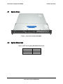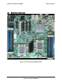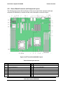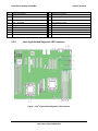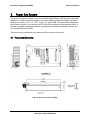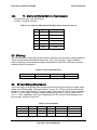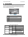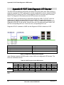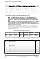
1
Intel® Server System SR1630BC Technical Product Specification Intel order number E44588-003 Revision 1.3 June, 2009 Enterprise Platforms and Services Division - Marketing Revision History Intel® Server System SR1630BC Revision History Date January 2009 Revision Number 1.0 Modifications March 2009 1.1 Updated system feature set table April 2009 1.2 Updated Appendix B: POST Code Diagnostic LED Decoder according to BIOS EPS. Updated Appendix C: POST Error Messages and Handling according to BIOS EPS. Updated “System Status LED Indicator States Table”. Removed AXXHERAL option from “Rack and Cabinet Mounting Options” section. Removed S4 state option from the “Power / Sleep LED” section. Updated cable length in the “Cable Harness Definition” table. May 2009 1.3 Updated memory description in “Table 1. System Feature Set”. Initial Release Disclaimers Information in this document is provided in connection with Intel® products. No license, express or implied, by estoppel or otherwise, to any intellectual property rights is granted by this document. Except as provided in Intel's Terms and Conditions of Sale for such products, Intel assumes no liability whatsoever, and Intel disclaims any express or implied warranty, relating to sale and/or use of Intel products including liability or warranties relating to fitness for a particular purpose, merchantability, or infringement of any patent, copyright or other intellectual property right. Intel products are not intended for use in medical, life saving, or life sustaining applications. Intel may make changes to specifications and product descriptions at any time, without notice. Designers must not rely on the absence or characteristics of any features or instructions marked "reserved" or "undefined." Intel reserves these for future definition and shall have no responsibility whatsoever for conflicts or incompatibilities arising from future changes to them. This document contains information on products in the design phase of development. Do not finalize a design with this information. Revised information will be published when the product is available. Verify with your local sales office that you have the latest datasheet before finalizing a design. The server boards / systems referenced in this document may contain design defects or errors known as errata which may cause the product to deviate from published specifications. Current characterized errata are available on request. Intel, Pentium, Itanium, and Xeon are trademarks or registered trademarks of Intel Corporation. *Other brands and names may be claimed as the property of others. Copyright © Intel Corporation 2009. All rights reserved. Revision 1.3 ii Intel order number E44588-003 Intel® Server System SR1630BC Introduction Table of Contents 1. 2. Introduction............................................................................................................................. 5 1.1 Chapter Outline ......................................................................................................... 5 1.2 Server System Use Disclaimer ................................................................................ 5 Product Overview.................................................................................................................... 6 2.1 System Views ........................................................................................................... 8 2.2 System Dimensions ................................................................................................... 8 2.3 System Components.................................................................................................. 9 2.4 Hard Drive and Peripheral Bays................................................................................ 11 2.5 Server Board Overview ........................................................................................... 12 2.5.1 Server Board Connector and Component Layout.................................................. 13 2.5.2 Intel® Light-Guided Diagnostic LED Locations....................................................... 14 2.5.3 Riser Card.............................................................................................................. 15 2.6 3. Power Sub-System ................................................................................................................ 16 3.1 Mechanical Overview............................................................................................... 16 3.2 Output Connectors .................................................................................................. 18 3.2.1 P1 – Main Power Connector ..................................................................................... 18 3.2.2 P2 – Processor/DDR3 Power Connector ................................................................... 18 3.2.3 P3 – Power Signal Connector ................................................................................... 19 3.2.4 P4 and P5 – SATA Hard Drive Power Connectors...................................................... 19 3.2.5 P6 – Slim-line SATA Optical Disk Drive Power Connector........................................... 20 3.3 Efficiency ................................................................................................................ 20 3.4 AC Input Voltage Requirement................................................................................. 20 3.5 Protection Circuits................................................................................................... 21 3.5.1 Over-current Protection (OCP) ................................................................................. 21 3.5.2 Over-voltage Protection (OVP)................................................................................. 21 3.5.3 Over-temperature Protection (OTP) ......................................................................... 22 3.6 4. Rack and Cabinet Mounting Options ......................................................................... 15 AC Power Cord Specification Requirements.............................................................. 22 Cooling Sub-System ............................................................................................................... 23 4.1.1 System Fan Connectors ........................................................................................... 24 1 Revision 1.3 Intel order number E44588-003 Intel® Server System SR1630BC 5. 6. Introduction 4.2 Power Supply Fans.................................................................................................. 25 4.3 Processor Air Duct and Air Baffle ............................................................................. 25 Peripheral and Hard Drive Support......................................................................................... 26 5.1 Optical Drive Support............................................................................................... 27 5.2 Hard Disk Drive Support .......................................................................................... 27 Front Control Panel................................................................................................................ 28 6.1.1 Power / Sleep LED ................................................................................................... 29 6.1.2 System Status LED .................................................................................................. 29 6.1.3 Drive Activity LED ................................................................................................... 30 7. PCI Riser Cards and Assembly ................................................................................................ 31 8. Environmental and Regulatory Specifications......................................................................... 32 8.1 System Level Environmental Limits.......................................................................... 32 8.2 Serviceability and Availability................................................................................... 32 8.3 Replacing the CMOS Battery .................................................................................... 33 8.4 Product Regulatory Compliance ............................................................................... 34 8.5 Use of Specified Regulated Components .................................................................. 34 8.6 Electromagnetic Compatibility Notices ..................................................................... 37 8.6.1 USA ........................................................................................................................ 37 8.6.2 FCC Verification Statement...................................................................................... 38 8.6.3 ICES-003 (Canada) ................................................................................................... 38 8.6.4 Europe (CE Declaration of Conformity) ..................................................................... 38 8.6.5 Japan EMC Compatibility........................................................................................... 38 8.6.6 BSMI (Taiwan) ......................................................................................................... 38 8.6.7 RRL (Korea)............................................................................................................. 39 8.6.8 CNCA (CCC-China) .................................................................................................... 39 8.7 Product Ecology Compliance .................................................................................... 39 8.8 Other Markings........................................................................................................ 42 Appendix A: Integration and Usage Tips ....................................................................................... 43 Appendix B: POST Code Diagnostic LED Decoder........................................................................... 44 Appendix C: POST Error Messages and Handling ........................................................................... 49 Glossary ....................................................................................................................................... 54 Reference Documents .................................................................................................................. 55 Revision 1.3 2 Intel order number E44588-003 Intel® Server System SR1630BC Introduction List of Figures Figure 1. Intel® Server System SR1630BC................................................................................... 8 Figure 2. Major System Components – Intel® Server System SR1630BC ................................... 9 Figure 3. Back Panel Features ................................................................................................... 10 Figure 4. Drive Bays – Intel® Server System SR1630BC ........................................................... 11 Figure 5. Intel® Server Board S5500BC picture .......................................................................... 12 Figure 6. Intel® Server Board S5500BC Layout .......................................................................... 13 Figure 7. Intel® Light-Guided Diagnostic LED Locations............................................................. 14 Figure 8. Overview of power Supply ........................................................................................... 16 Figure 9. Power Supply Mechanical Drawing ............................................................................. 17 Figure 10. AC Power Cord Drawing............................................................................................ 22 Figure 11. Fan Module Assembly – Intel® Server System SR1630BC ....................................... 23 Figure 12. Air Duct for the Intel® Server System SR1630BC...................................................... 25 Figure 13. Peripheral Location.................................................................................................... 26 Figure 14. Front Control Panel – Intel® Server System SR1630BC............................................ 28 Figure 15. PCI Riser Card Assembly .......................................................................................... 31 Figure 16. Diagnostic LED Placement Diagram ......................................................................... 44 3 Revision 1.3 Intel order number E44588-003 Intel® Server System SR1630BC Introduction List of Tables Updated memory description in “Table 1. System Feature Set”. .................................................. ii Table 2. System Feature Set ........................................................................................................ 6 Table 3. Intel® Server System SR1630BC Dimensions ................................................................ 8 Table 4. Board Layout reference ................................................................................................ 13 Table 5. Intel® Light-Guided Diagnostic LED reference .............................................................. 15 Table 6. Cable Harness Definition .............................................................................................. 18 Table 7. P1 – Main Power Connector Pin-out............................................................................. 18 Table 8. P2 – Processor/DDR3 Power Connector Pin-out ......................................................... 19 Table 9. P3 –Power Signal Connector Pin-out............................................................................ 19 Table 10. P4 and P5 – SATA Hard Drive Power Connector Pin-out........................................... 19 Table 11. P6 – Slim-line SATA Optical Disk Drive Power Connector Pin-out............................. 20 Table 12. Power Supply Efficiency ............................................................................................. 20 Table 13. AC Input Rating........................................................................................................... 20 Table 14. Over-current Protection (OCP) ................................................................................... 21 Table 15. Over-Voltage Protection (OVP) Limits ........................................................................ 21 Table 16. Cooling Zones............................................................................................................. 24 Table 17. System Fan Connector Pin-outs ................................................................................. 24 Table 18. Control Panel LED Functions...................................................................................... 28 Table 19. SSI Power LED Operation .......................................................................................... 29 Table 20. System Status LED Indicator States........................................................................... 29 Table 21. System Environmental Limits Summary ..................................................................... 32 Table 22. System Maintenance Procedure Times ...................................................................... 33 Table 23. Product Safety & Electromagnetic (EMC) Compliance ............................................... 35 Table 24. Product Ecology Compliance Reference Table .......................................................... 40 Table 25. POST Progress Code LED Example .......................................................................... 44 Table 26. Diagnostic LED POST Code Decoder ........................................................................ 45 Table 27. SEL Format for POST Error Messages ...................................................................... 49 Table 28. POST Error Messages and Handling.......................................................................... 49 Table 29. POST Error Beep Codes ............................................................................................ 52 Revision 1.3 4 Intel order number E44588-003 Intel® Server System SR1630BC 1. Introduction Introduction This Technical Product Specification (TPS) provides system specific information detailing the features, functionality, and high level architecture of the Intel® Server System SR1630BC. You should also reference the Intel® Server Board S5500BC Technical Product Specification more details regarding the functionality and architecture specific to the integrated server board and what is supported in this server system. The Intel® Server System SR1630BC may contain design defects or errors known as errata which may cause the product to deviate from published specifications. Refer to the Intel® Server Board S5500BC/ Intel® Server System SR1630BC Specification Update for published errata. 1.1 Chapter Outline This document is divided into the following chapters: Chapter 1 – Introduction Chapter 2 – Product Overview Chapter 3 – Power Sub-System Chapter 4 – Cooling Sub-System Chapter 5 – Peripheral and Drive Support Chapter 6 – Front Control Panel Chapter 7 – PCI Riser Card and Assembly Chapter 8 – Environmental and Regulatory Specifications Appendix A – Integration and Usage Tips Appendix B – POST Code Diagnostic LED Decoder Appendix C – Post Error Message and Handling Glossary Reference Documents 1.2 Server System Use Disclaimer Intel® Server Systems support add-in peripherals and contain a number of high-density VLSI and power delivery components that need adequate airflow to cool. Intel ensures through its own chassis development and testing that when Intel server building blocks are used together, the fully integrated system will meet the intended thermal requirements of supported components. It is the responsibility of the system integrator who chooses not to use Intel developed server building blocks to consult vendor datasheets and operating parameters to determine the amount of air flow required for their specific application and environmental conditions. Intel Corporation cannot be held responsible if components fail or the server system does not operate correctly when used outside any of their published operating or non-operating limits. 5 Revision 1.3 Intel order number E44588-003 Intel® Server System SR1630BC 2. Product Overview Product Overview The Intel® Server System SR1630BC is a 1U server system designed to support the Intel® Server Board S5500BC. The server board and the system have features designed to support the high-density server market. This chapter provides a high-level overview of the system features. Greater detail for each major system component or feature is provided in the following chapters. Table 2. System Feature Set Feature Description Dimensions • 1.7 inches (43.3 mm) high • 16.9 inches (430 mm) wide • 20 inches (508 mm) deep • 22 pounds (10 kg) weight Server Board Intel® Server Board S5500BC Processor ® ® ® LGA 1366 sockets supporting up to two Intel Xeon processor 5500 series with Intel QuickPath Interconnect (QPI) and Integrated Memory controllers. • Supports up to 95 W Thermal Design Power (TDP) ® ® 4.8 GT/s, 5.86 GT/s, and 6.4 GT/s Intel QuickPath Interconnect (Intel QPI) EVRD11.1 For a complete list of supported processors, see: http://support.intel.com/support/motherboards/server/s5500bc/compat.htm Memory Chipset Peripheral Interfaces Eight DDR3 DIMM slots supporting up to 32 GB of DDR3 800/166/1333 MT/s ECC Registered (RDIMM), or ECC Unbuffered (UDIMM) DDR3 memory • Four slots support CPU_1 and four slots support CPU_2. NOTE: Mixed memory is not tested or supported. Non-ECC memory is not tested and is not recommended for use in a server environment ® • Intel I/O Hub (IOH) 5500 chipset ® • Intel 82801Jx I/O Controller Hub 10 Raid (ICH10R) • ServerEngines* LLC Pilot II BMC controller (Integrated BMC) External connections: DB-15 video connector (back) RJ-45 serial Port A connector Two RJ-45 10/100/1000 Mb network connections Four USB 2.0 connectors (back) One USB 2.0 connector (front) Internal connections: Two USB 2x5 pin header, each supports two USB 2.0 ports One DH-10 Serial Port B header Six Serial ATA (SATA) II connectors One SSI-EEB compliant front panel header One SSI-EEB compliant 24-pin main power connector One SSI-compliant 8-pin CPU power connector One SSI-compliant 5-pin auxiliary power connector One 4-Pin SGPIO connector Revision 1.3 6 Intel order number E44588-003 Intel® Server System SR1630BC Product Overview Feature Description Add-in PCI, PCI Express* Cards Slot6 on server board supports one riser card supporting one half-length low-profile (6.6 inches) PCI Express* Gen2 x8 connector with X8 link width (support riser card) Video On-board ServerEngines* LLC Pilot II BMC controller Integrated 2D video controller 64 MB DDR2 667 MHz Memory LAN Two 10/100/1000 NICs One 82574LGbE PCI Express* Network Controller connects to the Gen2 x1 ® interface on the Intel 5500 IOH chipset. One 82567 Gigabit Network Connection that connects to the Gigabit LAN Connect ® Interface / LAN Connect Interface on the Intel ICH10R Two 10/100/1000 Base-TX Interfaces through RJ-45 connectors with integrated magnetics. Link and Speed LEDs on the RJ-45 Connector. Expansion Capabilities One x8 PCI Express* Gen 2 PCI riser slot capable of supporting one low-profile half-length PCI Express* add-in card which consumes power less than 15 W Hard Drive Options Fixed mount hard drive system: two SATA drives Peripherals • Slimline bay for slimline SATA optical drive • One PCI Express* x8 Add-in Card slot (Gen 2) Control Panel • Standard control panel LEDs and displays LEDs with standard control panel: NIC1 Activity NIC2 Activity Power / Sleep System Status Hard Drive Activity ® Intel Light-Guided diagnostic LEDs: Fan Fault DIMM Fault CPU Fault 5V-STBY System State POST Code Diagnostics Power Supply Single 400-W power supply Fans Two 97 x 94 x 33 mm, non-redundant, variable-speed system blower fans Two non-redundant 40 mm power supply internal fans Server Management On-board ServerEngines* LLC Pilot II Controller Integrated Baseboard Management Controller (Integrated BMC), IPMI 2.0 compliant Integrated Super I/O on LPC interface ® Support for Intel Server Management Software System Management ® Intel System Management Software 7 Revision 1.3 Intel order number E44588-003 Intel® Server System SR1630BC 2.1 Product Overview System Views Figure 1. Intel® Server System SR1630BC 2.2 System Dimensions Table 3. Intel® Server System SR1630BC Dimensions Height 1.7 inches Width without rails 16.9 inches Depth without CMA 20 inches Maximum weight 22 pounds Revision 1.3 8 Intel order number E44588-003 Intel® Server System SR1630BC 2.3 Product Overview System Components A Rack handles (two) F CPU Heatsink (two) B Processor air duct G System blower fans (two) C System memory DIMM sockets H Hard drives (two) D PCI add-in card bracket I Control panel E Power supply J Slimline optical drive Figure 2. Major System Components – Intel® Server System SR1630BC Note: The I/O connector locations on the back of the chassis are pre-cut, making an I/O shield unnecessary. You must install the supplied EMI gasket to maintain electromagnetic interference (EMI) compliance levels. 9 Revision 1.3 Intel order number E44588-003 Intel® Server System SR1630BC A Product Overview AC Power Connector E NIC 2 Connector (10 / 100 / 1000 Mb) BMC Management Port B Serial Port A F USB Ports 6 and 7 C Video Connector G USB Ports 8 and 9 D NIC 1 Connector (10 / 100 / 1000 Mb) H PCI Express* Slot Figure 3. Back Panel Features Revision 1.3 10 Intel order number E44588-003 Intel® Server System SR1630BC 2.4 Product Overview Hard Drive and Peripheral Bays The Intel® Server System SR1630BC is designed to support up to two fixed 3.5-inch Serial ATA (SATA) hard drives and one slimline optical device. A Slimline optical drive bay B Hard drive bay HDD0 (located under the slimline optical drive bay) C Hard drive bay HDD1 Figure 4. Drive Bays – Intel® Server System SR1630BC 11 Revision 1.3 Intel order number E44588-003 Intel® Server System SR1630BC 2.5 Product Overview Server Board Overview Figure 5. Intel® Server Board S5500BC picture Revision 1.3 12 Intel order number E44588-003 Intel® Server System SR1630BC Product Overview 2.5.1 Server Board Connector and Component Layout The following figure shows the board layout of the server board. Each connector and major component is identified by a number or letter, and a description is below the figure. Figure 6. Intel® Server Board S5500BC Layout Table 4. Board Layout reference A SATA 3 Description B Description Internal dual port USB2.0 header C SATA 5 D SATA 4 E Slot 3, PCI Express* x4 F Slot 4, PCI 32-bit/33 MHz G Intel® RMM3 slot H Slot 5, PCI Express* x8 I Slot 6, PCI Express* x8 (Riser card) J Slot 7, PCI Express* x8 K Back panel I/O ports L Diagnostic LEDs M Status LED N ID LED O External Serial B header P SATA Key 13 Revision 1.3 Intel order number E44588-003 Intel® Server System SR1630BC Product Overview Q Description System fan 3 header R Main power connector Description S DIMM sockets for Channel A & B (Supports CPU_1) T Power Supply Auxiliary Connector U SSI 24-pin Front Panel connector V System fan 2 header W CPU_1 fan header X CPU Power Connector Y CPU_1 Socket Z Intel® IOH 5500 chipset AA CPU Socket 2 BB CPU 2 fan header CC System fan 1 header DD DIMM sockets for Channels D and E (Supports CPU_2) EE SATA SGPIO FF SATA 0 GG SATA 1 HH SATA 2 2.5.2 Intel® Light-Guided Diagnostic LED Locations Figure 7. Intel® Light-Guided Diagnostic LED Locations Revision 1.3 14 Intel order number E44588-003 Intel® Server System SR1630BC Product Overview Table 5. Intel® Light-Guided Diagnostic LED reference 2.5.3 A Description Post-Code Diagnostic LEDs B Description Status LED C System ID LED D HDD LED E System Fan 3 Fault LED F 5 VSB LED G DIMM Fault LED H System Fan 2 Fault LED I CPU 1 Fan Fault LED J CPU 2 Fan Fault LED K System Fan 1 Fault LED L DIMM Fault LED Riser Card The system supports one PCI riser card that has one PCI Express* Gen2 x8 connector with X8 link width that supports one half-length half-height (6.6 inches) riser card consuming 15 W or less of power. 2.6 Rack and Cabinet Mounting Options You can install the Intel® Server System SR1630BC in 19-inch wide by up to 30-inch deep server cabinets. The system supports two rack mount options: A fixed mount relay rack / cabinet mount kit that can be configured to mount the system into either a 2-post or 4-post rack cabinet. (Product order code for the cabinet mount kit: AXXBRACKETS.) A basic slide rail kit designed to mount the chassis into a standard 19-inch by up to 30inch deep EIA-310D compatible server cabinet. (Product order code for the slide rail kit: AXXBASICRAIL.) 15 Revision 1.3 Intel order number E44588-003 Intel® Server System SR1630BC 3. Power Sub-System Power Sub-System The power sub-system consists of one, non-redundant high efficiency 400-W power supply that supports a 1U rack mount server system. The power supply and the power supply sub-system will have six outputs: 3.3 V, 5 V, 12 V1, 12V2, -12 V, and 5 VSB. The input is auto-ranging and power factor corrected. The form factor is EPS1U at 240 mm depth and wire harness output. It provides integrated management features, including over-temperature protection circuitry and over-voltage protection circuitry. The power supply provides two non-redundant 40 mm fans for self-cooling. 3.1 Mechanical Overview Figure 8. Overview of power Supply Revision 1.3 16 Intel order number E44588-003 Intel® Server System SR1630BC Power Sub-System Figure 9. Power Supply Mechanical Drawing Notes: 1. All dimensions are in mm. 2. The tolerance of the 40 mm height dimension (marked with letter C) pertains to the metal case only. 17 Revision 1.3 Intel order number E44588-003 Intel® Server System SR1630BC Power Sub-System 3.2 Output Connectors The power supply has a cable harness with five power connectors used to power various platform sub-systems. The following table defines each power connector. Table 6. Cable Harness Definition 3.2.1 Label Length (mm) Description P1 P2 P3 P4 P5 380 300 380 350 145 Main Power Connector Processor/DDR3 Power Connector Power Signal Connector P4 SATA drive power connector P5 SATA drive power connector P6 200 Slim SATA DVD power connector P1 – Main Power Connector Connector housing: 24-pin Molex* Mini-Fit Jr. 39-01-2245 (94V2) or equivalent Contact: Molex* Mini-Fit Jr, Crimp 5558 or equivalent Table 7. P1 – Main Power Connector Pin-out Pin 1 Signal +3.3 VDC 18 Awg Color Orange Pin 13 Signal +3.3 VDC 18 Awg Color Orange 2 +3.3 VDC Orange 14 -12 VDC Blue 3 COM Black 15 COM Black 4 +5 VDC 1 Red 16 PSON# Green 5 COM Black 17 COM Black 6 +5 VDC Red 18 COM Black 7 COM Black 19 COM Black 8 PWR OK Gray 20 Reserved N.C. 9 5 VSB Purple 21 +5 VDC Red 10 +12 V Yellow/Black 22 +5 VDC Red 11 +12 V Yellow/Black 23 +5 VDC Red 12 +3.3 VDC Orange 24 COM Black Notes: 1. 5V Remote Sense double-crimped into pin 4. 3.2.2 P2 – Processor/DDR3 Power Connector Connector housing: 8-pin Molex* 39-01-2085 (94V2) or equivalent Contact: Molex*, Mini-Fit Jr, HCS, 44476-1111 or equivalent Revision 1.3 18 Intel order number E44588-003 Intel® Server System SR1630BC Power Sub-System Table 8. P2 – Processor/DDR3 Power Connector Pin-out 3.2.3 Pin 1 Signal COM 18 Awg Color Black Pin 5 Signal +12V1 18 Awg Color Yellow 2 COM Black 6 +12V1 Yellow 3 COM Black 7 +12V1 Yellow 4 COM Black 8 +12V1 Yellow P3 – Power Signal Connector Connector housing: 5-pin Molex* 50-57-9705 (94V2) or equivalent Contacts: Molex* 16-02-0087 or equivalent Table 9. P3 –Power Signal Connector Pin-out Pin Signal 1 3.2.4 24 Awg Color 2 White/Green Stripe 2 I C Clock 2 I C Data White/Yellow Stripe 3 Reserved NC 4 COM Black 5 3.3RS White/Brown Stripe P4 and P5 – SATA Hard Drive Power Connectors Connector housing: JWT* A3811H00-5P (94V2) or equivalent Contact: JWT* A3811TOP-0D or equivalent Table 10. P4 and P5 – SATA Hard Drive Power Connector Pin-out Pin Signal 18 Awg Color 1 +3.3 V Orange 2 COM Black 3 +5VDC Red 4 COM Black 5 +12 V Yellow/Black 19 Revision 1.3 Intel order number E44588-003 Intel® Server System SR1630BC 3.2.5 Power Sub-System P6 – Slim-line SATA Optical Disk Drive Power Connector Connector housing: 6-pin SATA Power Contact: 15u plating minimum Table 11. P6 – Slim-line SATA Optical Disk Drive Power Connector Pin-out Pin Signal 22 AWG Color 1 Reserved N.C. 2 +5 VDC Red 3 +5 VDC Red 4 Reserved N.C. 5 COM Black 6 COM Black 3.3 Efficiency The following table provides the required minimum efficiency level at various loading conditions. These are provided at three different load levels: 100%, 50%, and 20%. Output should be loaded according to the proportional loading method defined by 80 Plus. Efficiency should be tested per 80 plus requirement. Table 12. Power Supply Efficiency Loading Minimum Efficiency 3.4 100% of Maximum 82% 50% of Maximum 85% 20% of Maximum 82% AC Input Voltage Requirement The power supply must operate within all specified limits over the following input voltage range, shown in the following table. Harmonic distortion of up to 10% THD must not cause the power supply to go out of specified limits. The power supply shall power off if the AC input is less than 75 VAC +/- 5 VAC range. The power supply should start up if the AC input is greater than 85 VAC +/- 4 VAC. Application of an input voltage below 85 VAC shall not cause damage to the power supply, including a fuse blow. Table 13. AC Input Rating Parameter Voltage (110) Minimum 90 Vrms Rated 100-127 Vrms Maximum 140 Vrms Voltage (220) 180 Vrms 200-240 Vrms 264 Vrms Frequency 47 Hz Start up VAC 85Vac +/-4Vac Power Off VAC 75Vac +/-5Vac 63 Hz Revision 1.3 20 Intel order number E44588-003 Intel® Server System SR1630BC 3.5 Power Sub-System Protection Circuits Protection circuits inside the power supply should cause only the power supply’s main outputs to shut down. If the power supply latches off due to a protection circuit tripping, an AC cycle off for 15 seconds and a PSON# cycle high for 1 second should be able to reset the power supply. 3.5.1 Over-current Protection (OCP) The power supply should have current limit to prevent the +3.3 V, +5 V, and +12 V outputs from exceeding the values shown in the following table. If the current limits are exceeded, the power supply will shut down and latch off. You can clear the latch by toggling the PSON# signal or with an AC power interruption. The power supply should not be damaged from repeated power cycling in this condition. -12 V and 5 VSB should be protected under over-current or shorted conditions so no damage can occur to the power supply. Auto-recovery feature is a requirement on 5 VSB rail. Table 14. Over-current Protection (OCP) Voltage +3.3 V +5 V 3.5.2 Over-current Limit (Iout limit) 110% minimum (= 16.5 A) ; 150% maximum (= 22.5 A) 110% min (= 11.0 A); 150% max (= 15.0 A) +12 V1 26 A min; 36 A max +12 V2 10 A min; 15 A max -12 V 0.625 A min; 2.0 A max 5 VSB 6.0 A max Over-voltage Protection (OVP) The power supply over-voltage protection should be locally sensed. The power supply will shut down and latch off after an over-voltage condition occurs. You can clear this latch by toggling the PSON# signal or with an AC power interruption. The following table contains the overvoltage limits. The values are measured at the output of the power supply’s connectors. The voltage should never exceed the maximum levels when measured at the power pins of the power supply connector during any single point of fail. The voltage should never trip any lower than the minimum levels when measured at the power pins of the power supply connector. Exception: +5 VSB rail should be able to recover after an over-voltage condition occurs. Table 15. Over-Voltage Protection (OVP) Limits Output Voltage +3.3 V Minimum (V) 3.9 Maximum (V) 4.5 +5 V 5.7 6.2 21 Revision 1.3 Intel order number E44588-003 Intel® Server System SR1630BC 3.5.3 Power Sub-System Output Voltage +12 V1,2 Minimum (V) 13.3 Maximum (V) 14.5 -12 V -13.3 -14.5 +5 VSB 5.7 6.5 Over-temperature Protection (OTP) The power supply is protected against over temperature conditions caused by loss of fan cooling or excessive ambient temperature. In an OTP condition, the power supply shuts down. When the power supply temperature drops to within specified limits, the power supply automatically restores power, while the 5 VSB remains always on. The OTP circuit must have built-in hysteresis such that the power supply will not oscillate on and off due to temperature recovering condition. The OTP trip level should have a minimum of 4 C of ambient temperature hysteresis. 3.6 AC Power Cord Specification Requirements The AC power cord must meet the following specification requirements: Cable Type Wire size SJT 16 AWG Temperature rating 105º C Amperage rating 13 A Voltage rating 125 V Figure 10. AC Power Cord Drawing Revision 1.3 22 Intel order number E44588-003 Intel® Server System SR1630BC 4. Cooling Sub-System Cooling Sub-System The cooling sub-system consists of two 97 x 94 x 33mm blower fans and a system air duct. These components provide the necessary cooling and airflow to the system. A fan on the processor heatsink is not needed. You must properly install the air duct and the top cover to maintain the required airflow within the system. Note: The Intel® Server System SR1630BC does not support redundant cooling. If a fan blower fails, you must power down the system as soon as possible so you can replace the failed fan blower. AF001524 Figure 11. Fan Module Assembly – Intel® Server System SR1630BC 23 Revision 1.3 Intel order number E44588-003 Intel® Server System SR1630BC Cooling Sub-System Table 16. Cooling Zones Cooling Zone CPU2 Fan System fan blower left System fan blower right 4.1.1 CPU1 Greatest Cooling Influence Primary cooling for CPU2, system memory, and PCIE card on riser card Primary cooling for CPU1, IOH, and system memory System Fan Connectors ® The Intel Server System SR1630BC supports two system fan blowers. The pin-out for the connector is provided in the following table. Table 17. System Fan Connector Pin-outs Pin J3K2 - SYS_FAN1 Signal Name Pin J8K3 - SYS_FAN2 Signal Name 1 GND 1 GND 2 P12V 2 P12V 3 FAN_TACH 3 FAN_TACH 4 FAN_PWM_SYS1 4 FAN_PWM_SYS2 Revision 1.3 24 Intel order number E44588-003 Intel® Server System SR1630BC 4.2 Cooling Sub-System Power Supply Fans The power supply incorporates two, non-redundant 40 mm fans for self-cooling. They are responsible for the cooling of the power supply. 4.3 Processor Air Duct and Air Baffle The system requires the use of the system air duct to direct airflow and sustain appropriate air pressure. Figure 12. Air Duct for the Intel® Server System SR1630BC 25 Revision 1.3 Intel order number E44588-003 Intel® Server System SR1630BC 5. Peripheral and Hard Drive Support Peripheral and Hard Drive Support The Intel® Server System SR1630BC provides support for two fixed hard drive bays and one slim-line peripheral drive bay at the front of the system. The fixed hard drive bays are designed to support SATA 3.5-inch drives. Item Feature A Slimline optical drive bay B Hard drive bay HDD0 (located under the slim-line optical drive bay) C Hard drive bay HDD1 Figure 13. Peripheral Location Revision 1.3 26 Intel order number E44588-003 Intel® Server System SR1630BC 5.1 Peripheral and Hard Drive Support Optical Drive Support The system provides a slimline drive bay that you can configure for a SATA optical CD-ROM or a DVD / CD-R drive. Drives are mounted on a tray which allows for easy installation into and removal from the system. The drive assembly is inserted in to the slim-line drive bay. A SATA cable connects the drive assembly to a SATA connector on the server board. The slimline devices are not hot-swappable. 5.2 Hard Disk Drive Support The Intel® Server System SR1630BC can support up to two 3.5-inch by 1-inch fixed SATA hard disk drives. The drives are mounted inside the systems. 27 Revision 1.3 Intel order number E44588-003 Intel® Server System SR1630BC 6. Front Control Panel Front Control Panel The standard control panel supports a power button, status LED, hard drive activity LED, and NIC 1 and NIC 2 activity LEDs. The control panel assembly comes pre-assembled into the system. The control panel assembly module slides into a predefined slot on the front of the system. Once installed, communication to the server board is achieved through a standard 24pin cable connected directly to the server board. A B C D E F G AF001000 Item A B Feature USB port Power button. This button also functions as a sleep button if enabled by an ACPI-compliant operating system. C Status LED D System power LED E Hard drive activity LED F NIC 1 LED G NIC 2 LED Figure 14. Front Control Panel – Intel® Server System SR1630BC Table 18. Control Panel LED Functions LED NIC1 / NIC2 Activity Power / Sleep (on standby power) Color Green Green Green Off Green System Status (on standby power) Amber Off State On Blink On Blink Off On Blink On Blink Off Description NIC Link/no access LAN access Power on Sleep / ACPI S1 state Power Off Running / normal operation System ready, but degraded Critical or non-recoverable condition. Possible critical power module failure, critical fan failure, voltage (power supply), voltage and thermal fault Non-critical condition. POST / system stop. System not ready Revision 1.3 28 Intel order number E44588-003 Intel® Server System SR1630BC LED Front Control Panel Color Green Off Disk Activity State Random blink Off Description HDD access No hard disk activity The current limiting resistors for the power LED, system fault LED, and NIC LEDs are located on the Intel® Server Board S5500BC. 6.1.1 Power / Sleep LED Table 19. SSI Power LED Operation State Power Off Power Mode Non-ACPI LED Off Description System power is off, and the BIOS has not initialized the chipset. Power On Non-ACPI On System power is on, but the BIOS has not yet initialized the chipset. Mechanical is off, and the operating system has not saved any context to the hard disk (soft-off state). S5 ACPI Off S3-S1 ACPI Slow blink 1 S0 ACPI Steady on DC power is still on. The operating system has saved context and gone into a level of low-power state (sleep state). System and the operating system are up and running (working state). Note: 1. The blink rate is ~ 1Hz with at 50% duty cycle. 6.1.2 System Status LED Table 20. System Status LED Indicator States Color Off State N/A Criticality Not ready Green Solid on Ok Green Blink Degraded Description System not ready: Post error/NMI event/PCI or terminator missing System booted and ready System degraded: Non-critical temperature threshold asserted. Non-critical voltage threshold asserted. Non-critical fan threshold asserted. Fan redundancy lost, sufficient system cooling maintained. This does not apply to non-redundant systems. Power supply predictive failure. Power supply redundancy lost. This does not apply to nonredundant systems. Correctable errors over a threshold of 10 and migrating to a spare DIMM (memory sparing). This indicates the user no longer has spared DIMMs indicating a redundancy lost condition. Corresponding DIMM LED should light up.1 29 Revision 1.3 Intel order number E44588-003 Intel® Server System SR1630BC Color State Criticality Amber Blink Non-critical Front Control Panel Description Non-fatal alarm – system is likely to fail: CATERR asserted. Critical temperature threshold asserted. Critical voltage threshold asserted. Critical fan threshold asserted. VRD hot asserted. Amber 6.1.3 Solid on SMI Timeout asserted. Fatal alarm – system has failed or shutdown: CPU Missing. Thermtrip asserted. Non-recoverable temperature threshold asserted. Non-recoverable voltage threshold asserted. Power fault / Power Control Failure. Fan redundancy lost, insufficient system cooling. This does not apply to non-redundant systems. Power supply redundancy lost, insufficient system power. This does not apply to non-redundant systems. This state will also happen when AC power is first applied to the system. This indicates that the BMC is booting. Critical, nonrecoverable Drive Activity LED The drive activity LED on the front panel indicates drive activity from the onboard hard disk controllers. Revision 1.3 30 Intel order number E44588-003 Intel® Server System SR1630BC 7. PCI Riser Cards and Assembly PCI Riser Cards and Assembly The Intel® Server Board S5500BC provides one PCI Express* x8 slot which supports one riser card with one riser card slot. The riser card supports one low-profile, half-length PCI Express* x8 add-in card which consumes power less than 15 W. Figure 15. PCI Riser Card Assembly 31 Revision 1.3 Intel order number E44588-003 Appendix A: Integration and Usage Tips 8. Environmental and Regulatory Specifications 8.1 System Level Environmental Limits The following table defines the system level operating and non-operating environmental limits. Table 21. System Environmental Limits Summary Parameter Operating Temperature Limits +10 C to +35 C with the maximum rate of change not to exceed 10 C per hour Non-Operating Temperature -40 C to +70 C Non-Operating Humidity 90%, non-condensing at 35 C Acoustic noise Sound power: 7.0 BA in an idle state at typical office ambient temperature. (23 +/- 2 degrees C) Shock, operating Half sine, 2 g peak, 11 mSec Shock, unpackaged Trapezoidal, 25 g, velocity change 136 inches/sec (≧40 lbs to > 80 lbs) Shock, packaged Non-palletized free fall in height of 24 inches (≧40 lbs to > 80 lbs) Vibration, unpackaged 5 Hz to 500 Hz, 2.20 g RMS random Shock, operating Half sine, 2 g peak, 11 mSec ESD* +/-15 KV except I/O port +/-8 KV per the Intel Environmental test specification System Cooling Requirement in BTU/Hr 2550 BTU/hour * IMPORTANT NOTES: The host system with the Intel® Server Board S5500BC requires the use of shielded LAN cable to comply with Immunity regulatory requirements. Use of non-shielded cables may result in the product having insufficient immunity electromagnetic effects, which may cause improper operation of the product. 8.2 Serviceability and Availability The system is designed to be serviced by qualified technical personnel only. The recommended Mean Time To Repair (MTTR) of the system is 30 minutes including diagnosis of the system problem. To meet this goal, the system enclosure and hardware were designed to minimize the MTTR. Following are the maximum times that a trained field service technician should take to perform the listed system maintenance procedures, after diagnosing the system and identifying the failed component. Revision 1.3 32 Intel order number E44588-003 Intel® Server Board S5000VCL TPS Appendix A: Integration and Usage Tips Table 22. System Maintenance Procedure Times Activity Remove cover Time Estimate 1 min Remove and replace hard disk drive 8.3 5 min Remove and replace power supply module 1 min Remove and replace system fan 7 min Remove and replace control panel module 2 min Remove and replace baseboard 15 min Replacing the CMOS Battery The lithium battery on the server board powers the real time clock (RTC) for several years in the absence of power. When the battery starts to weaken, it loses voltage, and the server settings stored in CMOS RAM in the RTC (for example, the date and time) may be wrong. Contact your customer service representative or dealer for a list of approved devices. WARNING Danger of explosion if battery is incorrectly replaced. Replace only with the same or equivalent type recommended by the equipment manufacturer. Discard used batteries according to manufacturer’s instructions. ADVARSEL! Lithiumbatteri - Eksplosionsfare ved fejlagtig håndtering. Udskiftning må kun ske med batteri af samme fabrikat og type. Levér det brugte batteri tilbage til leverandøren. ADVARSEL Lithiumbatteri - Eksplosjonsfare. Ved utskifting benyttes kun batteri som anbefalt av apparatfabrikanten. Brukt batteri returneres apparatleverandøren. VARNING Explosionsfara vid felaktigt batteribyte. Använd samma batterityp eller en ekvivalent typ som rekommenderas av apparattillverkaren. Kassera använt batteri enligt fabrikantens instruktion. VAROITUS Paristo voi räjähtää, jos se on virheellisesti asennettu. Vaihda paristo ainoastaan laitevalmistajan suosittelemaan tyyppiin. Hävitä käytetty paristo valmistajan ohjeiden mukaisesti. 33 Revision 1.3 Intel order number E44588-003 Appendix A: Integration and Usage Tips 8.4 Product Regulatory Compliance The server chassis product, when correctly integrated per this guide, complies with the following safety and electromagnetic compatibility (EMC) regulations. Intended Application – This product was evaluated as Information Technology Equipment (ITE), which may be installed in offices, schools, computer rooms, and similar commercial type locations. The suitability of this product for other product categories and environments (such as: medical, industrial, telecommunications, NEBS, residential, alarm systems, test equipment, etc.), other than an ITE application, may require further evaluation. Notifications to Users on Product Regulatory Compliance and Maintaining Compliance To ensure regulatory compliance, you must adhere to the assembly instructions in this guide to ensure and maintain compliance with existing product certifications and approvals. Use only the described, regulated components specified in this guide. Use of other products / components will void the UL listing and other regulatory approvals of the product and will most likely result in noncompliance with product regulations in the region(s) in which the product is sold. To help ensure EMC compliance with your local regional rules and regulations, before computer integration, make sure that the chassis, power supply, and other modules have passed EMC testing using a server board with a microprocessor from the same family (or higher) and operating at the same (or higher) speed as the microprocessor used on this server board. The final configuration of your end system product may require additional EMC compliance testing. For more information please contact your local Intel Representative. This is an FCC Class A device and its use is intended for a commercial type market place. 8.5 Use of Specified Regulated Components To maintain the UL listing and compliance to other regulatory certifications and/or declarations, the following regulated components must be used and conditions adhered to. Interchanging or use of other component will void the UL listing and other product certifications and approvals. Updated product information for configurations can be found on the Intel Server Builder Web site at the following URL: http://www.intel.com/go/serverbuilder If you do not have access to Intel’s Web address, please contact your local Intel representative. Server chassis (base chassis is provided with power supply and fans)UL listed. Server boardyou must use an Intel server board—UL recognized. Add-in boardsmust have a printed wiring board flammability rating of minimum UL94V1. Add-in boards containing external power connectors and/or lithium batteries must be UL recognized or UL listed. Any add-in board containing modem telecommunication circuitry must be UL listed. In addition, the modem must have the appropriate telecommunications, safety, and EMC approvals for the region in which it is sold. Peripheral Storage Devices - must be UL recognized or UL listed accessory and TUV or VDE licensed. Maximum power rating of any one device or combination of devices can not exceed manufacturer’s specifications. Total server configuration is not to exceed the maximum loading conditions of the power supply. Revision 1.3 34 Intel order number E44588-003 Intel® Server Board S5000VCL TPS Appendix A: Integration and Usage Tips The following table references Server Chassis Compliance and markings that may appear on the product. Markings below are typical markings however, may vary or be different based on how certification is obtained. Note: The Intel® Server System SR1630BC meets Class A Certifications Emissions requirements. Table 23. Product Safety & Electromagnetic (EMC) Compliance Compliance Regional Description Australia / New Zealand Compliance Reference Compliance Reference Marking Example AS/NZS 3548 (Emissions) N232 Argentina IRAM Certification (Safety) Belarus Belarus Certification Canada / USA CSA 60950 – UL 60950 (Safety) Industry Canada ICES-003 (Emissions) FCC CFR 47, Part 15 (Emissions) China CNCA – CB4943 (Safety) GB 9254 (Emissions) GB17625 (Harmonics) CENELEC Europe Low Voltage Directive 93/68/EEC; EMC Directive 89/336/EEC EN55022 (Emissions) EN55024 (Immunity) EN61000-3-2 (Harmonics) EN61000-3-3 (Voltage Flicker) CE Declaration of Conformity GS Certification – EN60950 Germany International None Required CANADA ICES-003 CLASS A CANADA NMB-003 CLASSE A This device complies with Part 15 of the FCC Rules. Operation of this device is subject to the following two conditions: (1) This device may not cause harmful interference, and (2) This device must accept interference receive, including interference that may cause undesired operation. CB Certification – IEC60950 CISPR 22 / CISPR 24 None Required 35 Revision 1.3 Intel order number E44588-003 Appendix A: Integration and Usage Tips Compliance Regional Description Compliance Reference Japan VCCI Certification Korea RRL Certification MIC Notice No. 1997-41 (EMC) & 1997-42 (EMI) Russia GOST-R Certification GOST R 29216-91 (Emissions) GOST R 50628-95 (Immunity) Ukraine Ukraine Certification Taiwan BSMI CNS13438 Compliance Reference Marking Example 인증번호: CPU-Model Name (A) None Required R33025 Revision 1.3 36 Intel order number E44588-003 Intel® Server Board S5000VCL TPS 8.6 Appendix A: Integration and Usage Tips Electromagnetic Compatibility Notices 8.6.1 USA This device complies with Part 15 of the FCC Rules. Operation is subject to the following two conditions: (1) this device may not cause harmful interference, and (2) this device must accept any interference received, including interference that may cause undesired operation. For questions related to the EMC performance of this product, contact: Intel Corporation 5200 N.E. Elam Young Parkway Hillsboro, OR 97124 1-800-628-8686 This equipment has been tested and found to comply with the limits for a Class A digital device, pursuant to Part 15 of the FCC Rules. These limits are designed to provide reasonable protection against harmful interference in a residential installation. This equipment generates, uses, and can radiate radio frequency energy and, if not installed and used in accordance with the instructions, may cause harmful interference to radio communications. However, there is no guarantee that interference will not occur in a particular installation. If this equipment does cause harmful interference to radio or television reception, which can be determined by turning the equipment off and on, the user is encouraged to try to correct the interference by one or more of the following measures: Reorient or relocate the receiving antenna. Increase the separation between the equipment and the receiver. Connect the equipment to an outlet on a circuit other than the one to which the receiver is connected. Consult the dealer or an experienced radio/TV technician for help. Any changes or modifications not expressly approved by the grantee of this device could void the user’s authority to operate the equipment. The customer is responsible for ensuring compliance of the modified product. Only peripherals (computer input/output devices, terminals, printers, etc.) that comply with FCC Class B limits may be attached to this computer product. Operation with noncompliant peripherals is likely to result in interference to radio and TV reception. All cables used to connect to peripherals must be shielded and grounded. Operation with cables, connected to peripherals that are not shielded and grounded may result in interference to radio and TV reception. 37 Revision 1.3 Intel order number E44588-003 Appendix A: Integration and Usage Tips 8.6.2 FCC Verification Statement Product Type: SR1630; S5500BC This device complies with Part 15 of the FCC Rules. Operation is subject to the following two conditions: (1) This device may not cause harmful interference, and (2) this device must accept any interference received, including interference that may cause undesired operation. For questions related to the EMC performance of this product, contact: Intel Corporation 5200 N.E. Elam Young Parkway Hillsboro, OR 97124-6497 Phone: 1 (800)-INTEL4U or 1 (800) 628-8686 8.6.3 ICES-003 (Canada) Cet appareil numérique respecte les limites bruits radioélectriques applicables aux appareils numériques de Classe A prescrites dans la norme sur le matériel brouilleur: “Appareils Numériques”, NMB-003 édictée par le Ministre Canadian des Communications. (English translation of the notice above) This digital apparatus does not exceed the Class A limits for radio noise emissions from digital apparatus set out in the interference-causing equipment standard entitled “Digital Apparatus,” ICES-003 of the Canadian Department of Communications. 8.6.4 Europe (CE Declaration of Conformity) This product has been tested in accordance too, and complies with the Low Voltage Directive (73/23/EEC) and EMC Directive (89/336/EEC). The product has been marked with the CE Mark to illustrate its compliance. 8.6.5 Japan EMC Compatibility Electromagnetic Compatibility Notices (International) English translation of the notice above: This is a Class A product based on the standard of the Voluntary Control Council For Interference (VCCI) from Information Technology Equipment. If this is used near a radio or television receiver in a domestic environment, it may cause radio interference. Install and use the equipment according to the instruction manual. 8.6.6 BSMI (Taiwan) The BSMI Certification number and the following warning is located on the product safety label which is located on the bottom side (pedestal orientation) or side (rack mount configuration). Revision 1.3 38 Intel order number E44588-003 Intel® Server Board S5000VCL TPS 8.6.7 Appendix A: Integration and Usage Tips RRL (Korea) Following is the RRL certification information for Korea. English translation of the notice above: 1. 2. 3. 4. 5. Type of Equipment (Model Name): On License and Product Certification No.: On RRL certificate. Obtain certificate from local Intel representative Name of Certification Recipient: Intel Corporation Date of Manufacturer: Refer to date code on product Manufacturer/Nation: Intel Corporation/Refer to country of origin marked on product 8.6.8 CNCA (CCC-China) The CCC Certification Marking and EMC warning is located on the outside rear area of the product. 声明 此为A级产品,在生活环境中,该产品可能会造成无 线电干扰。在这种情况下,可能需要用户对其干扰采 取可行的措施。 8.7 Product Ecology Compliance Intel has a system in place to restrict the use of banned substances in accordance with world wide product ecology regulatory requirements. The following is Intel’s product ecology compliance criteria. 39 Revision 1.3 Intel order number E44588-003 Appendix A: Integration and Usage Tips Table 24. Product Ecology Compliance Reference Table Compliance Regional Description Compliance Reference California California Code of Regulations, Title 22, Division 4.5; Chapter 33: Best Management Practices for Perchlorate Materials. China China RoHS Administrative Measures on the Control of Pollution Caused by Electronic Information Products” (EIP) #39. Referred to as China RoHS. Mark requires to be applied to retail products only. Mark used is the Environmental Friendly Use Period (EFUP). Number represents years. Compliance Reference Marking Example Special handling may apply. See www.dtsc.ca.gov/hazardo uswaste/perchlorate This notice is required by California Code of Regulations, Title 22, Division 4.5; Chapter 33: Best Management Practices for Perchlorate Materials. This product / part includes a battery which contains Perchlorate material. China Recycling (GB18455-2001) Mark requires to be applied to be retail product only. Marking applied to bulk packaging and single packages. Not applied to internal packaging such as plastics, foams, etc. Intel Internal Specification Europe All materials, parts and subassemblies must not contain restricted materials as defined in Intel’s Environmental Product Content Specification of Suppliers and Outsourced Manufacturers – http://supplier.intel.com/ehs/environmental.htm Waste Electrical and Electronic Equipment (WEEE) Directive 2002/96/EC – Mark applied to system level products only. European Directive 2002/95/EC Restriction of Hazardous Substances (RoHS) Threshold limits and banned substances are noted below. Quantity limit of 0.1% by mass (1000 PPM) for: Lead, Mercury, Hexavalent Chromium, Polybrominated Biphenyls Diphenyl Ethers (PBB/PBDE) Quantity limit of 0.01% by mass (100 PPM) for: Cadmium Germany None Required None Required German Green Dot Applied to Retail Packaging Only for Boxed Boards Revision 1.3 40 Intel order number E44588-003 Intel® Server Board S5000VCL TPS Compliance Regional Description Intel Internal Specification International Appendix A: Integration and Usage Tips Compliance Reference All materials, parts and subassemblies must not contain restricted materials as defined in Intel’s Environmental Product Content Specification of Suppliers and Outsourced Manufacturers – http://supplier.intel.com/ehs/environmental.htm ISO11469 - Plastic parts weighing >25gm are intended to be marked with per ISO11469. Compliance Reference Marking Example None Required >PC/ABS< Recycling Markings – Fiberboard (FB) and Cardboard (CB) are marked with international recycling marks. Applied to outer bulk packaging and single package. Japan Japan Recycling Applied to Retail Packaging Only for Boxed Boards 41 Revision 1.3 Intel order number E44588-003 Appendix A: Integration and Usage Tips 8.8 Other Markings Compliance Description Stand-by Power Compliance Reference Compliance Reference Marking Example 60950 Safety Requirement Applied to product is stand-by power switch is used. . Multiple Power Cords 60950 Safety Requirement Applied to product if more than one power cord is used. Ground Connection 60950 Deviation for Nordic Countries Country of Origin Logistic Requirements Applied to products to indicate where product was made. English: This unit has more than one power supply cord. To reduce the risk of electrical shock, disconnect (2) two power supply cords before servicing. Simplified Chinese: 注意: 本设备包括多条电源系统电缆。 为避免遭受电击,在进行维修之 前应断开两(2)条电源系统电 缆。 Traditional Chinese: 注意: 本設備包括多條電源系統電纜。 為避免遭受電擊,在進行維修之 前應斷開兩(2)條電源系統電 纜。 German: Dieses Geräte hat mehr als ein Stromkabel. Um eine Gefahr des elektrischen Schlages zu verringern trennen sie beide (2) Stromkabeln bevor Instandhaltung. Line1 : “WARNING:” Swedish on line2: “Apparaten skall anslutas till jordat uttag, när den ansluts till ett nätverk.” Finnish on line 3: “Laite on liitettävä suojamaadoituskoskettimilla varustettuun pistorasiaan.” English on line 4: “Connect only to a properly earth grounded outlet.” Made in XXXX Revision 1.3 42 Intel order number E44588-003 Intel® Server Board S5000VCL TPS Appendix A: Integration and Usage Tips Appendix A: Integration and Usage Tips This section provides a list of useful information unique to the Intel® Server System SR1630BC that you should keep in mind while integrating the server system. The Intel® Server System SR1630BC requires the use of a shielded LAN cable to comply with Immunity regulatory requirements. Intel® Remote Management Module 3 is not supported the Intel® Server System SR1630BC. The Intel® Server system SR1630BC supports one riser card that supports one lowprofile half-length PCI Express* x8 add-in card which consumes power less than 15 W. Processor fans are not needed and are not supported. The system fan module provides the necessary cooling needed for the system. You must use the system air duct to maintain system thermals. System fans are not hot-swappable. A screw on the front edge of the top cover is required when the unit is installed in a useraccessible environment. The FRUSDR utility must be run to load the proper sensor data records for the server chassis onto the server board. Make sure the latest system software is loaded. This includes the system BMC firmware, FRUSDR, and BIOS. You can download the latest system software from: http://support.intel.com/support/motherboards/server/S5500BC/ 43 Revision 1.3 Intel order number E44588-003 Appendix B: POST Code Diagnostic LED Decoder Appendix B: POST Code Diagnostic LED Decoder The BIOS executes platform configuration processes during the system boot. Each process is assigned a specific hex POST code number. As each configuration routine is started, the BIOS displays the POST code on the POST Code Diagnostic LEDs on the back edge of the server board. The Diagnostic LEDs identify the last POST process to be executed. Each POST code is represented by the eight amber Diagnostic LEDs. The POST codes are divided into two nibbles: an upper nibble and a lower nibble. The upper nibble bits are represented by Diagnostic LEDs #4, #5, #6, and #7. The lower nibble bits are represented by Diagnostics LEDs #0, #1, #2, and #3. Given the bit is set in the upper and lower nibbles, and then the corresponding LED is lit. If the bit is clear, corresponding LED is off. Diagnostic LED #7 is labeled as “MSB” and the Diagnostic LED #0 is labeled as “LSB”. A. ID LED F. Diagnostic LED #4 B. Status LED G. Diagnostic LED #3 C. Diagnostic LED #7 (MSB LED) H. Diagnostic LED #2 D. Diagnostic LED #6 I. Diagnostic LED #1 E. Diagnostic LED #5 J. Diagnostic LED #0 (LSB LED) Figure 16. Diagnostic LED Placement Diagram In the following example, the BIOS sends a value of ACh to the diagnostic LED decoder. The LEDs are decoded as follows: Table 25. POST Progress Code LED Example Upper Nibble LEDs Status MSB LED #7 8h ON 1 LED #6 4h OFF 0 LED #5 2h ON 1 Lower Nibble LEDs LED #4 1h OFF 0 LED #3 8h ON 1 Ah LED #2 4h ON 1 LED #1 2h OFF 0 LSB LED #0 1h OFF 0 Ch Upper nibble bits = 1010b = Ah; Lower nibble bits = 1100b = Ch; the two are concatenated as ACh. Revision 1.3 44 Intel order number E44588-003 Appendix B: POST Code Diagnostic LED Decoder Table 26. Diagnostic LED POST Code Decoder Diagnostic LED Decoder O = On, X=Off Checkpoint Upper Nibble Lower Nibble Description MSB LSB 8h 4h 2h 1h 8h 4h 2h 1h LED #7 #6 #5 #4 #3 #2 #1 #0 Multi-use code – This POST Code is used in different contexts. 0xF2h O O O O X X O X Seen at the start of Memory Reference Code (MRC) Start of the very early platform initialization code Very late in POST, it is the signal that the operating system has switched to virtual memory mode Memory Error Codes (Accompanied by a beep code) Note that these are codes used in early POST by Memory Reference Code. Later in POST these same codes are used for other Progress Codes. (These progress codes are not controlled by BIOS and are subject to change at the discretion of the Memory Reference Code team.) 0xE8h No Usable Memory Error: No memory in the system, or SPD bad so O O O X O X X X no memory could be detected 0xEAh Channel Training Error: DQ/DQS training failed on a channel during O O O X O X O X memory channel initialization. If no usable memory remains, system is halted. 0xEBh 0xEDh O O O X O X O O Memory Test Error: memory failed Hardware BIST. Population Error: RDIMMs and UDIMMs cannot be mixed in the O O O X O O X O system 0xEEh O O O X O O O X Mismatch Error: more than 2 Quad Ranked DIMMS in a channel. Memory Reference Code Progress Codes (Not accompanied by a beep code) 0xB0h O X O O X X X X Chipset Initialization Phase 0xB1h O X O O X X X O Reset Phase 0xB2h O X O O X X O X DIMM Detection Phase 0xB3h O X O O X X O O Clock Initialization Phase 0Xb4h O X O O X O X X SPD Data Collection Phase 0Xb6h O X O O X O O X Rank Formation Phase 0xB8h O 0xB9h O 0xBAh O 0xBBh O 0xBCh O Host Processor X X X X X O O O O O O O O O O O O O O O X X X X O X X O O X X O X O X Channel Training Phase Memory Test Phase Memory Map Creation Phase RAS Initialization Phase MRC Complete 0x04h X X X O X O X X 0x10h 0x11h 0x12h 0x13h Chipset 0x21h Memory 0x22h 0x23h 0x24h 0x25h 0x26h 0x27h 0x28h PCI Bus 0x50h 0x51h X X X X X X X X X X X X O O O O X X X X X X X X X X O O X O X O Early processor initialization (flat32.asm) where system BSP is selected Power-on initialization of the host processor (bootstrap processor) Host processor cache initialization (including AP) Starting application processor initialization SMM initialization X X O X X X X O Initializing a chipset component X X X X X X X X X X X X X X O O O O O O O X X X X X X X X X X X X X O X X O O O O X O O X X O O X X O X O X O X Reading configuration data from memory (SPD on DIMM) Detecting presence of memory Programming timing parameters in the memory controller Configuring memory parameters in the memory controller Optimizing memory controller settings Initializing memory, such as ECC init Testing memory X X O O X X O O X X X X X X X O Enumerating PCI buses Allocating resources to PCI buses 45 Revision 1.3 Intel order number E44588-003 Appendix B: POST Code Diagnostic LED Decoder Diagnostic LED Decoder O = On, X=Off Checkpoint Upper Nibble Lower Nibble MSB LSB 8h 4h 2h 1h 8h 4h 2h 1h LED #7 #6 #5 #4 #3 #2 #1 #0 0x52h X O X O X X O X 0x53h X O X O X X O O 0x54h X O X O X O X X 0x55h X O X O X O X O 0X56h X O X O X O O X 0x57h X O X O X O O O USB 0x58h X O X O O X X X 0x59h X O X O O X X O ATA/ATAPI/SATA 0x5Ah X O X O O X O X 0x5Bh X O X O O X O O SMBUS 0x5Ch X O X O O O X X 0x5Dh X O X O O O X O Local Console 0x70h X O O O X X X X 0x71h X O O O X X X O 0x72h X O O O X X O X Remote Console 0x78h X O O O O X X X 0x79h X O O O O X X O 0x7Ah X O O O O X O X Keyboard (only USB) 0x90h O X X O X X X X 0x91h O X X O X X X O 0x92h O X X O X X O X 0x93h O X X O X X O O 0x94h O X X O X O X X 0x95h O X X O X O X O Mouse (only USB) 0x98h O X X O O X X X 0x99h O X X O O X X O 0x9Ah O X X O O X O X 0x9Bh O X X O O X O O Fixed Media 0xB0h O X O O X X X X 0xB1h O X O O X X X O 0xB2h O 0xB3h O Removable Media 0xB8h O 0xB9h O 0xBAh O Description Hot Plug PCI controller initialization Reserved for PCI bus Reserved for PCI bus Reserved for PCI bus Reserved for PCI bus Reserved for PCI bus Resetting USB bus Reserved for USB devices Resetting SATA bus and all devices Reserved for ATA Resetting SMBUS Reserved for SMBUS Resetting the video controller (VGA) Disabling the video controller (VGA) Enabling the video controller (VGA) Resetting the console controller Disabling the console controller Enabling the console controller Resetting the keyboard Disabling the keyboard Detecting the presence of the keyboard Enabling the keyboard Clearing keyboard input buffer Instructing keyboard controller to run Self Test(PS/2 only) Resetting the mouse Detecting the mouse Detecting the presence of mouse Enabling the mouse Resetting fixed media device Disabling fixed media device Detecting presence of a fixed media device (hard drive detection, and so forth.) Enabling / configuring a fixed media device X O O X X O X X O O X X O O X X O O O O O O X X X X X O X O O O X O X O O O X X Resetting removable media device Disabling removable media device Detecting presence of a removable media device (CD-ROM detection, and so forth.) Enabling / configuring a removable media device O O O O O X X X X X X X X X O X X O O X X O X O X Trying to boot device selection 0 Trying to boot device selection 1 Trying to boot device selection 2 Trying to boot device selection 3 Trying to boot device selection 4 0xBCh O X O Boot Device Selection (BDS) 0xD0 O O X 0xD1 O O X 0xD2 O O X 0xD3 O O X 0xD4 O O X Revision 1.3 46 Intel order number E44588-003 Appendix B: POST Code Diagnostic LED Decoder Diagnostic LED Decoder O = On, X=Off Checkpoint Upper Nibble Lower Nibble Description MSB LSB 8h 4h 2h 1h 8h 4h 2h 1h LED #7 #6 #5 #4 #3 #2 #1 #0 0xD5 X O X O Trying to boot device selection 5 O O X O 0xD6 O O X O X O O X Trying to boot device selection 6 0Xd7 O O X O X O O O Trying to boot device selection 7 O X X X Trying to boot device selection 8 0xD8 O O X O 0xD9 O O X O O X X O Trying to boot device selection 9 X O X Trying to boot device selection A 0xDA O O X O O 0xDB O O X O O X O O Trying to boot device selection B 0xDC O O X O O O X X Trying to boot device selection C 0xDD O O X O Trying to boot device selection D O O X O 0xDE O O O X Trying to boot device selection E O O X O 0xDF O O X O O O O O Trying to boot device selection F Pre-EFI Initialization (PEI) Core 0xE0h O O O X X X X X Started dispatching early initialization modules (PEIM) 0xE1h O O O X X X X O Reserved for Initializaiton module use (PEIM) 0xE2h O O O X X X O X Initial memory found, configured, and installed correctly 0xE3h O O O X X X O O Reserved for Initializaiton module use (PEIM) Driver eXecution Environment (DXE) Core (not accompanied by a beep code) 0xE4h O O O X X O X X Entered EFI driver execution phase (DXE) 0xE5h O O O X X O X O Started dispatching drivers 0xE6h O O O X X O O X Started connecting drivers DXE Drivers 0xE7h O O O X O O X O Waiting for user input 0xE8h O O O X O X X X Checking password 0xE9h O O O X O X X O Entering BIOS setup 0xEAh O O O X O X O X Flash Update 0xEEh O O O X O O O X Calling Int 19. One beep unless silent boot is enabled. 0xEFh O O O X O O O O Unrecoverable boot failure Runtime Phase / EFI Operating System Boot 0xF4h O O O O X O X X Entering Sleep state 0xF5h O O O O X O X O Exiting Sleep state Operating system has requested EFI to close boot services 0xF8h O O O O O X X X (ExitBootServices ( ) Has been called) Operating system has switched to virtual address mode 0xF9h O O O O O X X O (SetVirtualAddressMap ( ) Has been called) Operating system has requested the system to reset (ResetSystem 0xFAh O O O O O X O X ( ) has been called) Pre-EFI Initialization Module (PEIM) / Recovery 0x30h X X O O X X X X Crisis recovery has been initiated because of a user request 0x31h X X O O X X X O Crisis recovery has been initiated by software (corrupt flash) 0x34h X X O O X O X X Loading crisis recovery capsule 0x35h X X O O X O X O Handing off control to the crisis recovery capsule 0x3Fh X X O O O O O O Unable to complete crisis recovery capsule 47 Revision 1.3 Intel order number E44588-003 Appendix C: POST Error Messages and Handling Appendix C: POST Error Messages and Handling Whenever possible, the BIOS outputs the current boot progress codes on the video screen. Progress codes are 32-bit quantities plus optional data. The 32-bit numbers include class, subclass, and operation information. The class and subclass fields point to the type of hardware being initialized. The operation field represents the specific initialization activity. Based on the data bit availability to display progress codes, a progress code can be customized to fit the data width. The higher the data bit, the higher the granularity of information that can be sent on the progress port. The progress codes may be reported by the system BIOS or option ROMs. The Response section in the following table is divided into three types: Minor: The message displays on the screen or in the Error Manager screen. The system continues booting with a degraded state. The user may want to replace the erroneous unit. The setup POST error Pause setting does not have any effect with this error. Major: The message is displayed in the Error Manager screen and an error is logged to the SEL. The setup POST error Pause setting determines whether the system pauses to the Error Manager for this type of error where the user can take immediate corrective action or choose to continue booting. Fatal: The message displays in the Error Manager screen, an error is logged to the SEL, and the system cannot boot unless the error is resolved. The user must replace the faulty part and restart the system. The setup POST error Pause setting does not have any effect with this error. Table 27. SEL Format for POST Error Messages Generator ID 33h (BIOS POST) Sensor Type Code 0Fh (System Firmware Progress) Sensor number 06h (BIOS POST Error) Type code 6Fh (Sensor Specific Offset) Event Data1 A0h (OEM Codes in Data2 & Data3) Event Data2 xxh (Low Byte of POST Error Code) Event Data3 xxh (High Byte of POST Error Code) Table 28. POST Error Messages and Handling Error Code 0012 CMOS date / time not set Error Message Response Major 0048 Password check failed Major 0108 Keyboard component encountered a locked error. Minor 0109 Keyboard component encountered a stuck key error. Minor 0113 Fixed Media: The SAS RAID firmware can not run properly. The user should attempt to reflash the firmware. Major 0140 PCI component encountered a PERR error. Major 0141 PCI resource conflict Major 0146 PCI out of resources error Major 0192 Processor 0x cache size mismatch detected. Fatal 0193 Processor 0x stepping mismatch. Minor 0194 Processor 0x family mismatch detected. Fatal Revision 1.3 48 Intel order number E44588-003 Appendix C: POST Error Messages and Handling Error Code 0195 Error Message Processor 0x Intel(R) QPI speed mismatch. Response Major 0196 Processor 0x model mismatch. Fatal 0197 Processor 0x speeds mismatched. Fatal 0198 Processor 0x family is not supported. Fatal 019F Processor and chipset stepping configuration is unsupported. Major 5220 CMOS/NVRAM Configuration Cleared Major 5221 Passwords cleared by jumper Major 5224 Password clear Jumper is Set. Major 8160 Processor 01 unable to apply microcode update Major 8161 Processor 02 unable to apply microcode update Major 8180 Processor 0x microcode update not found. Minor 8190 Watchdog timer failed on last boot Major 8198 OS boot watchdog timer failure. Major 8300 Baseboard management controller failed self-test Major 84F2 Baseboard management controller failed to respond Major 84F3 Baseboard management controller in update mode Major 84F4 Sensor data record empty Major 84FF System event log full Minor 8500 Memory component could not be configured in the selected RAS mode. Major 8501 DIMM Population Error. Major 8502 CLTT Configuration Failure Error. Major 8520 DIMM_A1 failed Self Test (BIST). Major 8521 DIMM_A2 failed Self Test (BIST). Major 8522 DIMM_B1 failed Self Test (BIST). Major 8523 DIMM_B2 failed Self Test (BIST). Major 8524 DIMM_C1 failed Self Test (BIST). Major 8525 DIMM_C2 failed Self Test (BIST). Major 8526 DIMM_D1 failed Self Test (BIST). Major 8527 DIMM_D2 failed Self Test (BIST). Major 8528 DIMM_E1 failed Self Test (BIST). Major 8529 DIMM_E2 failed Self Test (BIST). Major 852A DIMM_F1 failed Self Test (BIST). Major 852B DIMM_F2 failed Self Test (BIST). Major 8540 DIMM_A1 Disabled. Major 8541 DIMM_A2 Disabled. Major 8542 DIMM_B1 Disabled. Major 8543 DIMM_B2 Disabled. Major 8544 DIMM_C1 Disabled. Major 8545 DIMM_C2 Disabled. Major 8546 DIMM_D1 Disabled. Major 8547 DIMM_D2 Disabled. Major 8548 DIMM_E1 Disabled. Major 8549 DIMM_E2 Disabled. Major 854A DIMM_F1 Disabled. Major 49 Revision 1.3 Intel order number E44588-003 Appendix C: POST Error Messages and Handling Error Code 854B DIMM_F2 Disabled. Error Message Response Major 8560 DIMM_A1 Component encountered a Serial Presence Detection (SPD) fail error. Major 8561 DIMM_A2 Component encountered a Serial Presence Detection (SPD) fail error. Major 8562 DIMM_B1 Component encountered a Serial Presence Detection (SPD) fail error. Major 8563 DIMM_B2 Component encountered a Serial Presence Detection (SPD) fail error. Major 8564 DIMM_C1 Component encountered a Serial Presence Detection (SPD) fail error. Major 8565 DIMM_C2 Component encountered a Serial Presence Detection (SPD) fail error. Major 8566 DIMM_D1 Component encountered a Serial Presence Detection (SPD) fail error. Major 8567 DIMM_D2 Component encountered a Serial Presence Detection (SPD) fail error. Major 8568 DIMM_E1 Component encountered a Serial Presence Detection (SPD) fail error. Major 8569 DIMM_E2 Component encountered a Serial Presence Detection (SPD) fail error. Major 856A DIMM_F1 Component encountered a Serial Presence Detection (SPD) fail error. Major 856B DIMM_F2 Component encountered a Serial Presence Detection (SPD) fail error. Major 85A0 DIMM_A1 Uncorrectable ECC error encountered. Major 85A1 DIMM_A2 Uncorrectable ECC error encountered. Major 85A2 DIMM_B1 Uncorrectable ECC error encountered. Major 85A3 DIMM_B2 Uncorrectable ECC error encountered. Major 85A4 DIMM_C1 Uncorrectable ECC error encountered. Major 85A5 DIMM_C2 Uncorrectable ECC error encountered. Major 85A6 DIMM_D1 Uncorrectable ECC error encountered. Major 85A7 DIMM_D2 Uncorrectable ECC error encountered. Major 85A8 DIMM_E1 Uncorrectable ECC error encountered. Major 85A9 DIMM_E2 Uncorrectable ECC error encountered. Major 85AA DIMM_F1 Uncorrectable ECC error encountered. Major 85AB DIMM_F2 Uncorrectable ECC error encountered. Major 8604 Chipset Reclaim of non critical variables complete. Minor 9000 Unspecified processor component has encountered a non specific error. Major 9223 Keyboard component was not detected. Minor 9226 Keyboard component encountered a controller error. Minor 9243 Mouse component was not detected. Minor 9246 Mouse component encountered a controller error. Minor 9266 Local Console component encountered a controller error. Minor 9268 Local Console component encountered an output error. Minor 9269 Local Console component encountered a resource conflict error. Minor 9286 Remote Console component encountered a controller error. Minor 9287 Remote Console component encountered an input error. Minor 9288 Remote Console component encountered an output error. Minor 92A3 Serial port component was not detected Major 92A9 Serial port component encountered a resource conflict error Major 92C6 Serial Port controller error Minor 92C7 Serial Port component encountered an input error. Minor 92C8 Serial Port component encountered an output error. Minor 94C6 LPC component encountered a controller error. Minor 94C9 LPC component encountered a resource conflict error. Major Revision 1.3 50 Intel order number E44588-003 Appendix C: POST Error Messages and Handling Error Code 9506 Error Message ATA/ATPI component encountered a controller error. Response Minor 95A6 PCI component encountered a controller error. Minor 95A7 PCI component encountered a read error. Minor 95A8 PCI component encountered a write error. Minor 9609 Unspecified software component encountered a start error. Minor 9641 PEI Core component encountered a load error. Minor 9667 PEI module component encountered a illegal software state error. Fatal 9687 DXE core component encountered a illegal software state error. Fatal 96A7 DXE boot services driver component encountered a illegal software state error. Fatal 96AB DXE boot services driver component encountered invalid configuration. Minor 96E7 SMM driver component encountered a illegal software state error. Fatal 0xA022 Processor component encountered a mismatch error. Major 0xA027 Processor component encountered a low voltage error. Minor 0xA028 Processor component encountered a high voltage error. Minor 0xA421 PCI component encountered a SERR error. Fatal 0xA500 ATA/ATPI ATA bus SMART not supported. Minor 0xA501 ATA/ATPI ATA SMART is disabled. Minor 0xA5A0 PCI Express component encountered a PERR error. Minor 0xA5A1 PCI Express component encountered a SERR error. Fatal 0xA5A4 PCI Express IBIST error. Major 0xA6A0 DXE boot services driver Not enough memory available to shadow a legacy option ROM. Minor 0xB6A3 DXE boot services driver Unrecognized. Major The following table lists POST error beep codes. Prior to system video initialization, the BIOS uses these beep codes to inform users of error conditions. The beep code is followed by a uservisible code on POST Progress LEDs. Table 29. POST Error Beep Codes Beeps 3 Error Message Memory error POST Progress Code Multiple Description System halted because a fatal error related to the memory was detected. The following Beep Codes are from the BMC, and are controlled by the Firmware team. They are listed here for convenience. 1-5-2-1 CPU: Empty slot / population error. N/A CPU sockets are populated incorrectly – CPU1 must be populated before CPU2. 1-5-4-2 Power fault: DC power unexpectedly lost (power good dropout) N/A Power unit sensors – power unit failure offset. 1-5-4-4 Power control fault (Power good assertion timeout) N/A Power unit sensors – soft power control failure offset. 51 Revision 1.3 Intel order number E44588-003 Appendix C: POST Error Messages and Handling In case of POST error(s) listed as Major, the BIOS enters the error manager and waits for the user to press an appropriate key before booting the operating system or entering the BIOS Setup. The user can override this option by setting the POST Error Pause option as disabled on the BIOS setup Main screen. If this option is disabled, the system boots the operating system without user intervention. The default is disabled. Revision 1.3 52 Intel order number E44588-003 Glossary Glossary Word / Acronym ACA Australian Communication Authority Definition ANSI American National Standards Institute BMC Baseboard Management Controller CMOS Complementary Metal Oxide Silicon D2D DC-to-DC EMP Emergency Management Port FP Front Panel FRB Fault Resilient Boot FRU Field Replaceable Unit LCD Liquid Crystal Display LPC Low-Pin Count MTBF Mean Time Between Failure MTTR Mean Time to Repair OTP Over-temperature Protection OVP Over-voltage Protection PFC Power Factor Correction PSU Power Supply Unit RI Ring Indicate SCA Single Connector Attachment SDR Sensor Data Record SE Single-Ended UART Universal Asynchronous Receiver Transmitter USB Universal Serial Bus VCCI Voluntary Control Council for Interference 53 Revision 1.3 Intel order number E44588-003 Reference Documents Reference Documents See the following documents for additional information: Intel® Server Board S5500BC Technical Product Specification Intel® Server Board S5500BC / Intel® Server Chassis SC5650 / Intel® Server System SR1630BC Spares/Parts List and Configuration Guide Intel® S5500 Chipsets Server Board BIOS External Product Specification Revision 1.3 54 Intel order number E44588-003