1
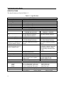
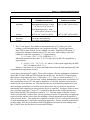
PORT POWERED
INSERTION READER
TECHNICAL REFERENCE MANUAL
Manual Part Number 99875129 Rev 18
MAY 2009
REGISTERED TO ISO 9001:2000
1710 Apollo Court
Seal Beach, CA 90740
Phone: (562) 546-6400
FAX: (562) 546-6301
Technical Support: (651) 415-6800
www.magtek.com
Copyright© 1998-2009
MagTek®, Inc.
Printed in the United States of America
Information in this document is subject to change without notice. No part of this document may
be reproduced or transmitted in any form or by any means, electronic or mechanical, for any
purpose, without the express written permission of MagTek, Inc.
MagTek is a registered trademark of MagTek, Inc.
REVISIONS
Rev Number
1
2
Date
7 Dec 98
29 Mar 99
3
14 Jun 99
4
5
1 Dec 99
11 Jan 00
6
14 Sep 00
7
8
6 Oct 00
01 Jan 01
9
20 Mar 01
10
11
01 Aug 01
27 Nov 01
12
09 Sep 02
13
21 Feb 03
14
15
13 Mar 03
13 May 03
16
26 Jun 03
17
9 May 07
18
25 May 09
ii
Notes
Initial Release
Title: Deleted Dual Head in order to add single head units; Section 1: Added 6 part
numbers and Windows Driver reference, added transfer rates to specification;
Section 2: Added Molex part number, added note to Table 2-1, removed connector
J5 from Figure 2-2, and added note for optional cable; Section 3: Added Figure
3-4, Timing.
Title: Dropped MT-215 and RS-232; Sec 2, added Table 2-2, Pin List, and changed
Figure 2-2 , added Pin Numbers for optional Cable 21040077.
Section 2: Updated J4 Connector Table.
Section 1: added Track 2-3 version to Table 1-1; Section 2: Clarified Fig 2-2 for
connector uses with Tracks. Remove cable 21051498; add cables 21051499 and
21041469. Section 3: added Track 2-3 version to “Reader to Host Formats” and to
“Timing for ID sign-on and Transmission Bursts.”
Section 1: Specifications, changed all cm dimensions to mm. Corrected
temperature ranges. Written to SI, International System of Units.
Section 1: Editorial; Section 3: Qualified Inquiry command for two models.
Front Matter: Changed copyright date; Changed warranty from 90 days to one
year; added agency approvals to current manual.
Front Matter: Added Address for Warranty RMA. Changed Agency approvals to
Class B. Section 2: Fig 2-1, Added to Back View “of Bezel”. Section 3: Added
Transmission examples. Added Appendix A. Bezel Design
Front Matter: Editorial corrections to CE and UL/CUL.
Sec 2, Fig 2-2: Added extended bezel illustration; Appendix A: Added extended
bezel mechanical drawing
Front Matter: added ISO line to logo, changed Tech Support phone number, added
new warranty statement. Editorial throughout. Sec 1: added two P/Ns to
Configurations, added statement to unbuffered mode. Sec 3: Editorial; Clarified
Table 3-2. Added new Appendix A, Optional Firmware Features. Changed
Appendix A to B.
Sec 2: Note added after Figure 2-3 stating cable with tie wrap adds approximately
.25 inch to length of unit.
Replaced some fonts so manual would print on all printers.
Front Matter: added ISO line to logo, changed Tech Support phone number, added
new warranty statement.
Changed operating temperature to before (32 oF) and after (-4 oF) 1 Nov 03
shipping date.
Removed 21065131 & 21066008; modified specifications to reflect change-over to
21063619.
Added 21065142. Updated Limited Warranty and Agency approvals.
LIMITED WARRANTY
MagTek warrants that the products sold pursuant to this Agreement will perform in accordance with MagTek’s
published specifications. This warranty shall be provided only for a period of one year from the date of the shipment
of the product from MagTek (the “Warranty Period”). This warranty shall apply only to the “Buyer” (the original
purchaser, unless that entity resells the product as authorized by MagTek, in which event this warranty shall apply
only to the first repurchaser).
During the Warranty Period, should this product fail to conform to MagTek’s specifications, MagTek will, at its
option, repair or replace this product at no additional charge except as set forth below. Repair parts and replacement
products will be furnished on an exchange basis and will be either reconditioned or new. All replaced parts and
products become the property of MagTek. This limited warranty does not include service to repair damage to the
product resulting from accident, disaster, unreasonable use, misuse, abuse, negligence, or modification of the product
not authorized by MagTek. MagTek reserves the right to examine the alleged defective goods to determine whether
the warranty is applicable.
Without limiting the generality of the foregoing, MagTek specifically disclaims any liability or warranty for goods
resold in other than MagTek’s original packages, and for goods modified, altered, or treated without authorization by
MagTek.
Service may be obtained by delivering the product during the warranty period to MagTek (1710 Apollo Court, Seal
Beach, CA 90740). If this product is delivered by mail or by an equivalent shipping carrier, the customer agrees to
insure the product or assume the risk of loss or damage in transit, to prepay shipping charges to the warranty service
location, and to use the original shipping container or equivalent. MagTek will return the product, prepaid, via a three
(3) day shipping service. A Return Material Authorization (“RMA”) number must accompany all returns. Buyers
may obtain an RMA number by contacting Technical Support at (888) 624-8350.
EACH BUYER UNDERSTANDS THAT THIS MAGTEK PRODUCT IS OFFERED
AS IS. MAGTEK MAKES NO OTHER WARRANTY, EXPRESS OR IMPLIED,
AND MAGTEK DISCLAIMS ANY WARRANTY OF ANY OTHER KIND,
INCLUDING ANY WARRANTY OF MERCHANTABILITY OR FITNESS FOR A
PARTICULAR PURPOSE.
IF THIS PRODUCT DOES NOT CONFORM TO MAGTEK’S SPECIFICATIONS, THE SOLE REMEDY SHALL
BE REPAIR OR REPLACEMENT AS PROVIDED ABOVE. MAGTEK’S LIABILITY, IF ANY, SHALL IN NO
EVENT EXCEED THE TOTAL AMOUNT PAID TO MAGTEK UNDER THIS AGREEMENT. IN NO EVENT
WILL MAGTEK BE LIABLE TO THE BUYER FOR ANY DAMAGES, INCLUDING ANY LOST PROFITS,
LOST SAVINGS, OR OTHER INCIDENTAL OR CONSEQUENTIAL DAMAGES ARISING OUT OF THE USE
OF, OR INABILITY TO USE, SUCH PRODUCT, EVEN IF MAGTEK HAS BEEN ADVISED OF THE
POSSIBILITY OF SUCH DAMAGES, OR FOR ANY CLAIM BY ANY OTHER PARTY.
LIMITATION ON LIABILITY
EXCEPT AS PROVIDED IN THE SECTIONS RELATING TO MAGTEK’S LIMITED WARRANTY,
MAGTEK’S LIABILITY UNDER THIS AGREEMENT IS LIMITED TO THE CONTRACT PRICE OF THIS
PRODUCT.
MAGTEK MAKES NO OTHER WARRANTIES WITH RESPECT TO THE PRODUCT, EXPRESSED OR
IMPLIED, EXCEPT AS MAY BE STATED IN THIS AGREEMENT, AND MAGTEK DISCLAIMS ANY
IMPLIED WARRANTY, INCLUDING WITHOUT LIMITATION ANY IMPLIED WARRANTY OF
MERCHANTABILITY OR FITNESS FOR A PARTICULAR PURPOSE.
MAGTEK SHALL NOT BE LIABLE FOR CONTINGENT, INCIDENTAL, OR CONSEQUENTIAL DAMAGES
TO PERSONS OR PROPERTY. MAGTEK FURTHER LIMITS ITS LIABILITY OF ANY KIND WITH
RESPECT TO THE PRODUCT, INCLUDING ANY NEGLIGENCE ON ITS PART, TO THE CONTRACT PRICE
FOR THE GOODS.
MAGTEK’S SOLE LIABILITY AND BUYER’S EXCLUSIVE REMEDIES ARE STATED IN THIS SECTION
AND IN THE SECTION RELATING TO MAGTEK’S LIMITED WARRANTY.
iii
FCC WARNING STATEMENT
This equipment has been tested and was found to comply with the limits for a Class B digital device pursuant to Part
15 of FCC Rules. These limits are designed to provide reasonable protection against harmful interference when the
equipment is operated in a residential environment. This equipment generates, uses, and can radiate radio frequency
energy and, if not installed and used in accordance with the instruction manual, may cause harmful interference with
radio communications. However, there is no guarantee that interference will not occur in a particular installation.
FCC COMPLIANCE STATEMENT
This device complies with Part 15 of the FCC Rules. Operation of this device is subject to the following two
conditions: (1) this device may not cause harmful interference, and (2) this device must accept any interference
received, including interference that may cause undesired operation.
CANADIAN DOC STATEMENT
This digital apparatus does not exceed the Class B limits for radio noise from digital apparatus set out in the Radio
Interference Regulations of the Canadian Department of Communications.
Le présent appareil numérique n’émet pas de bruits radioélectriques dépassant les limites applicables aux appareils
numériques de la classe B prescrites dans le Réglement sur le brouillage radioélectrique édicté par le ministère des
Communications du Canada.
This Class B digital apparatus complies with Canadian ICES-003.
Cet appareil numériqué de la classe B est conformé à la norme NMB-003 du Canada.
CE STANDARDS
Testing for compliance with CE requirements was performed by an independent laboratory. The unit under test was
found compliant with standards established for Class B devices.
UL/CSA
This product is recognized per Underwriter Laboratories and Canadian Underwriter Laboratories 1950.
RoHS STATEMENT
When ordered as RoHS compliant, this product meets the Electrical and Electronic Equipment (EEE) Reduction of
Hazardous Substances (RoHS) European Directive 2002/95/EC. The marking is clearly recognizable, either as
written words like “Pb-free”, “lead-free”, or as another clear symbol ( ).
iv
TABLE OF CONTENTS
SECTION 1. FEATURES AND SPECIFICATIONS----------------------------------------------------------------------1 FEATURES............................................................................................................................................... 1 CONFIGURATIONS ................................................................................................................................. 2 MODES OF OPERATION ........................................................................................................................ 2 Unbuffered Mode.................................................................................................................................. 2 Buffered Mode ...................................................................................................................................... 3 RELATED DOCUMENTS ......................................................................................................................... 3 SPECIFICATIONS.................................................................................................................................... 4 SECTION 2. INSTALLATION -------------------------------------------------------------------------------------------------7 CONNECTORS ........................................................................................................................................ 7 OPTIONAL RS-232 CABLE...................................................................................................................... 7 MOUNTING .............................................................................................................................................. 8 CARD INSERTION AND ORIENTATION............................................................................................... 12 SECTION 3. COMMANDS, FORMATS, TIMING----------------------------------------------------------------------- 13 HOST TO READER COMMANDS ......................................................................................................... 13 READER TO HOST FORMATS ............................................................................................................. 14 TIMING FOR ID SIGN-ON AND TRANSMISSION BURSTS................................................................. 16 TRANSMISSIONS EXAMPLES.............................................................................................................. 17 APPENDIX A. OPTIONAL FIRMWARE FEATURES ----------------------------------------------------------------- 19 JIS PORT POWERED INSERT READER.............................................................................................. 19 HALF CARD READER ........................................................................................................................... 19 APPENDIX B. BEZEL DESIGN -------------------------------------------------------------------------------------------- 21 FIGURES and TABLES
Figure 1-1. Port Powered Insertion Reader Configurations ----------------------------------------------------------- vi Table 1-1. Configurations*------------------------------------------------------------------------------------------------------2 Table 1-2. Specifications--------------------------------------------------------------------------------------------------------4 Table 2-1. J4 Connector - RS232---------------------------------------------------------------------------------------------7 Table 2-2. Pin List for Cables 21051499 and 21041469 ----------------------------------------------------------------7 Figure 2-1. MagTek Flat-Faced Bezel Mounting Dimensions----------------------------------------------------------9 Figure 2-2. MagTek Extended Bezel Mounting Dimensions --------------------------------------------------------- 10 Figure 2-3. Board Layout and Cable Connections---------------------------------------------------------------------- 11 Figure 2-4. Card Insertion and Orientation ------------------------------------------------------------------------------- 12 Table 3-1. Commands and Responses ----------------------------------------------------------------------------------- 13 Table 3-2. Options and Reader Responses------------------------------------------------------------------------------ 14 Figure 3-1. Timing For ID Sign-on and Transmission Bursts.-------------------------------------------------------- 16 Table 3-3. Transmission Data Examples Not in Buffered Mode ---------------------------------------------------- 17 Table 3-4. Transmission Data Examples in Buffered Mode With STX and ETX Included -------------------- 17 Table A-1. Options for 21088827 Firmware (JIS Reader) ------------------------------------------------------------ 19 Table A-2. Options for 21088828 Firmware (Half Card Reader) ---------------------------------------------------- 19 Figure B-1. Dimensions for Flat-Faced Bezel Design, Sheet 1------------------------------------------------------ 22 Figure B-2. Dimensions for Flat-Faced Bezel Design, Sheet 2------------------------------------------------------ 23 Figure B-3. Dimensions for Extended Bezel Design, Sheet 1 ------------------------------------------------------- 24 Figure B-4. Dimensions for Extended Bezel Design, Sheet 2 ------------------------------------------------------- 25 v
Figure 1-1. Port Powered Insertion Reader Configurations
vi
SECTION 1. FEATURES AND SPECIFICATIONS
The Port Powered Insertion Reader can be single or dual head configuration. Figure 1-1 shows
the Reader, the card orientation, and two bezel configurations. The dual head configuration can
read the card on insertion and removal with the magnetic stripe facing up or down. The single
head configuration can read the card on insertion and removal if the stripe is oriented to match
the position of the head.
The Reader also has circuitry that automatically ensures that the ISO magnetic stripe is read in
the case where a dual-stripe JIS (Japanese) credit card is inserted on the dual head unit.
The Reader conforms to the following specifications: ISO (International Standards
Organization), ANSI (American National Standards Institute). The Reader conforms to
specifications for Tracks 1 and 2 of the following 3-Track formats: AAMVA (American
Association of Motor Vehicle Administrators) and CDL (California Drivers License).
FEATURES
Features of the Reader are as follows:
• Port Powered RS-232 Interface – No power pack required, powered from PC port with
•
•
•
•
•
•
•
•
•
•
•
•
•
computers having an RS-232 interface.
Card Present Opto-sensor – Detects if card is fully inserted in Reader.
Single or Dual Read Head – Configuration can be Single or Dual Read Head.
JIS Discrimination circuitry – On dual head modules, automatically detects if a dual-stripe
JIS (Japanese Industrial Standard) card is inserted, and autoroutes the ISO data signals to
microcontroller. This ensures that dual-head features still work for Japanese card holders.
Mag-Stripe reading during insertion and removal of card – For reliable card reading.
Open Chassis design – Provides superior debris clearing capability.
Half-card Drop out – Allows half-sized credit cards and coins to be cleared from insert
channel.
Isolated PCB – Isolates electronics from debris and liquids.
AGC (Automatic Gain Control) in MagTek's latest read IC – Enhances read performance
with less susceptibility to RF interference.
Beam-mounted Read-heads – Provides superior tracking of bowed or warped cards.
Ruggedized Chassis and Bezel Material – Improves temperature and impact performance.
Command Selectable Buffered or Unbuffered Modes – Provides greater versatility of
operating modes.
Command Selectable Framing Characters – Provides selection of STX, ETX, ESC, and CR.
ASCII Message Format at 9600 bps.
1
Port Powered Insertion Reader
CONFIGURATIONS
Table 1-1 lists the part numbers, single or dual head, head positions, and bezel types.
Table 1-1. Configurations*
Part Number
Single or
Head Position**
Bezel
Track
Head
Dual Head
Connector
21065085
Single
Head down /left
No Bezel
1-2
J3
21065086
Single
Head up/right
No Bezel
1-2
J2
21065087
Single
Head down/left
Extended Bezel
1-2
J3
21065088
Single
Head up/right
Extended Bezel
1-2
J2
21065089
Single
Head down/left
Flat Faced Bezel
1-2
J3
21065090
Single
Head up/right
Flat Faced Bezel
1-2
J2
21065091
Dual
Both
No Bezel
1-2
J2, J3
21065092
Dual
Both
Extended Bezel
1-2
J2, J3
21065093
Dual
Both
Flat Faced Bezel
1-2
J2, J3
21065097
Single
Head down/left
Flat Faced Bezel
2-3
J2
21065142
Dual
Both
Flat Faced Bezel
1,2,3
J2, J3
*
Cables not supplied. (See Section 2 for descriptions of cables.)
** The magnetic stripe is inserted in the same orientation as the head position; for example,
Head down/left means Magnetic Stripe down or left.
MODES OF OPERATION
The Reader can operate in either unbuffered or buffered mode. The modes are described below.
The note that follows applies to both modes.
Note
The insertion and removal of the card must be done in a
continuous motion. If not, the Reader may not read the encoded
data properly. In that case, the Reader responds by either
transmitting the ASCII character “E” representing an error, or by
not transmitting any character, which indicates that the Reader
has not detected data and the card was not completely inserted.
Unbuffered Mode
When a card is inserted and removed, a read attempt is made during both insertion and removal.
If the read is successful, data (including the two sentinel characters) is sent to the PC. The data
is transmitted immediately after removing the card and not retained in the Reader.
When operating in the unbuffered mode, the Reader does not need to receive commands from the
host in order to transmit data or status characters, and data, if available; however, the Reader
does respond to an “Inquiry Command” by sending status characters. The inquiry command that
requests the transmission is the ESCAPE (ESC) character followed by “I” (0x49).
2
Section 1. Features and Specifications
In the unbuffered mode, data can be retrieved from the card after the card has been inserted and
while it is blocking the rear sensor. Issuing an “Inquiry Command” (see Section 3) will retrieve
data from the card.
Buffered Mode
When a card is inserted and removed, a read attempt is made during both insertion and removal.
Upon removal of the card if the read is successful, data (including the two sentinel characters) is
stored in a memory buffer on the Reader and is not transmitted until the Reader receives an
“Inquiry Command” from the host. This command is the ESCAPE character followed by “I”.
The data or error status is available when the back sensor is blocked, however the Release
Command will not clear the buffer. The Reader cannot read another card until the buffer is
cleared. To clear the buffer, the Host must transmit the ESCAPE character followed by “R”.
The unit will always output a 1 and enabled optional characters when the back sensor is first
blocked. It will output a 0 and enabled optional characters when the card has been withdrawn.
See Section 3, Table 3-4 for detailed examples.
RELATED DOCUMENTS
MagTek 99875125
The MagTek Device Drivers for Windows, Part Number
30037385; may be used with the Port Powered Insertion Reader.
The title of the manual is MagTek Device Drivers For Windows
Programming Reference Manual.
The Port Powered Insertion Reader will read cards that meet the standards defined by ISO
(International Standards Organization):
ISO 7811
ISO 7810
Identification Cards - Mag-stripe Cards, Tracks 1-3
Identification Cards - Physical Specifications (ID-1 Cards)
Available from ANSI
Phone 212-642-4900, www.ansi.org
3
Port Powered Insertion Reader
SPECIFICATIONS
The Specifications are listed in Table 1-2.
Table 1-2. Specifications
Reference Standards
Power Input
Interface Signal
Message Format
Tracks (tracks 1-2 versions)
Tracks (tracks 2-3 versions)
Track Card Speed
Head Life
DTR Voltage (Input)
VDTR
Transmit Data (TXD)
Receive Data (RXD)
Communication
(bursts of 5 ms transmit with
10 ms idle between bursts)
DTR Current
Or Auxiliary Supply Current
(Positive supply to unit)
Power On
Transmitting
Quiescent
RXD Current
Output Cable
Dimensions
Length
Width
Height
Bezel Thickness
Weight
4
OPERATING
ISO7810 and 7811; JIS B9561
From RS-232 Interface
RS-232 compatible
ASCII
Reads ISO Tk1 and Tk2 data locations
Reads ISO Tk2 and Tk3 data locations
3 to 100 IPS (7,6 to 250 cm/sec)
500,000 Insertion Cycles (1,000,000 head passes)
ELECTRICAL
Printed Circuit Board
Printed Circuit Board
21063608 (discontinued)
21063619 or 21063550
+5 to +15 VDC operating
+5 to +15 VDC operating
+16 VDC absolute maximum
+/-20 VDC absolute maximum
-25 VDC absolute maximum
+/-5 VDC minimum
+/-(VDTR – 0.4 V) VDC minimum
+/-15 VDC operating
+/-15 VDC operating
+/-25 VDC absolute maximum
+/-20 VDC absolute maximum
Transfer Rate: 9600 bps, 33%
Transfer Rate: 9600 bps, 33%
duty cycle; 8 data bits, no parity, 1
duty cycle; 8 data bits, no parity, 1
stop bit
stop bit
* 3.7 mA minimum required under
See below
all operating conditions with cable
capacitance limited to 1000pF
(and practically unlimited inrush
current)
12 mA Max (and practically
See above.
unlimited inrush current)
11 mA typical, 5 ms duration
See above.
6 mA typical, continuous
See above.
Within RS-232 specified limits
Average current approximates that
(does not function as a negative
of a normal RS-232 load.
supply to unit)
(Negative supply to unit)
Not Specified
See note “*” below.
MECHANICAL
Without bezel
With Flat-faced Bezel With Extended Bezel
4.4" (111.8 mm) 4.58" (116.3 mm)
5.09" (129.3 mm)
3.51" (89.2 mm) 4.00" (101.6 mm)
4.00" (101.6 mm)
1.24" (31.5 mm) 3.00" (76.2 mm)
3.00" (76.2 mm)
Flat Faced: 0.31" (7.9mm); Extended: 0.82" (20.8 mm)
Without bezel
With Flat-faced Bezel With Extended Bezel
2.25 oz (65 gr)
3.85 oz (109 gr)
4.02 oz (114 gr)
Section 1. Features and Specifications
ENVIRONMENTAL
Printed Circuit Board
21063608 (discontinued)
Temperature
Operating
Units shipped prior to Nov 1, 2003:
32 oF to 131 oF (0 oC to 55 oC)
Printed Circuit Board
21063619 or 21063550
-40°F to 158°F (-40°C to 70°C)
Units shipped after Nov 1, 2003:
-4 oF to 158 oF (-20 oC to 70 oC)
Storage
Humidity
Operating
Storage
-40 oF to 176 oF (-40 oC to 80 oC)
-40oF to 176oF (-40oC to 80oC)
10% to 90% noncondensing
Up to 100% noncondensing
*
The 3.7 mA figure is for continuous data transmission at 33% duty cycle while
reading a card with both heads at once (stripe on each side). Typical capacitance
from TXD is about 1000 pF for our standard 2 m cable. Minimum DTR current ‘IT’
required for continuous transmission at 33% duty cycle, while reading a card with
both heads, with cable capacitance ‘C’ is approximately:
IT = (3.5 mA) + (10 V) * 33% *(9600 Hz) / 2 * C.
Maximum transmission burst time ‘T’ at 33% duty cycle for RS-232 compatibility is
approximately:
T = (64 μF) * (5 V - 3.4 V) / (IT - IS), where IS is the current supplied by the DTR
line (T is unlimited for IS > IT)
Subtract 1 mA from IT if it is known that both heads will not be used simultaneously (this
is guaranteed on single-head versions).
A note about “port-powered” readers: These readers operate off some combination of otherwise
unused RS-232 lines, DTR and TXD from the host in this case. Per the RS-232 specification,
these lines are only required to drive a 3 kΩ load at +/-5 V. This is a current of merely 5 V / 3
kΩ=1.67 mA per line. All “port-powered” readers fundamentally require more current than 1.67
mA (consider that at least 1.67 mA must be supplied to a 3 kΩ load, and some extra current is
needed for the circuit that does so). Thus these readers are not technically guaranteed to work
unless multiple unused lines are used for power and/or some duty cycle limit is imposed on
transmitting while employing an energy storage device (a capacitor). In practice, however most
ports can easily supply the 2.7 mA at +5 V required by this new reader on DTR and the nearspecification average TXD (from host) current at -5 V. This new reader is MagTek’s lowest
current “port-powered” reader to date. Strictly speaking, some RS-232 ports may not supply the
required current, and this is the reason for including a current consumption specification for a
“port-powered” device. The current drive capability of an RS-232 port is not typically specified,
so experimentation may be required in a particular application. If more current is needed for the
positive supply, RTS may be paralleled with DTR (both host-referenced) in the cabling to the
unit. If this is done, the host must of course hold RTS high.
5
Port Powered Insertion Reader
6
SECTION 2. INSTALLATION
This section describes cabling information, mounting dimensions and PCB layout.
The installation consists of mounting the Reader and connecting the cable. The head may be on
top of the PCB, under the PCB, or if the unit has dual heads, both. The head, or heads, are
installed in the factory to customer specifications.
CONNECTORS
The connector pin list is shown in Table 2-1. The mating connector for J4 is Molex 51021-0400.
The terminals are Molex 50058-8000.
Table 2-1. J4 Connector - RS232
PIN NUMBER
SIGNAL (HOST AS REFERENCE)
J4-1
RXD (To PC)
J4-2
TXD (From PC)
J4-3
DTR (From PC)
J4-4
GND
All pins must be connected as shown.
OPTIONAL RS-232 CABLE
Optional serial cables, part numbers 21051499 (black) or 21041469 (white), are available. One
end connects to J4 and the other end is a DE-9 female. The pin list for the cable connectors is
shown in Table 2-2.
Table 2-2. Pin List for Cables 21051499 and 21041469
P1
SIGNAL
COLOR
1
NC*
-2
RXD
YELLOW
3
TXD
GREEN
4
DTR
ORANGE
5
GND
BROWN
6-9
NC*
-All pins must be connected as shown.
* NC = No connection
P2
-1
2
3
4
--
7
Port Powered Insertion Reader
MOUNTING
Figure 2-1 shows the dimensions for mounting when using a flat-faced MagTek Bezel.
Figure 2-2 shows the dimensions for mounting when using an extended MagTek Bezel. In these
configurations, the top view and the side view show the head mounted under the PCB with
connector J2 used. Note that for newer units (using PCB 21063619), the printed circuit board is
reduced in size from that shown, and the location of J4 is shifted.
The other head configurations are shown in Figure 1-1.
Note
For users who are interested in designing their own bezel, please
refer to the dimensions provided in Appendix A.
Figure 2-3 shows the board layout and indicates the cable connections for all head positions.
8
Section 2. Installation
of Bezel
Figure 2-1. MagTek Flat-Faced Bezel Mounting Dimensions
9
Port Powered Insertion Reader
.5
.72
.830
3.35
Figure 2-2. MagTek Extended Bezel Mounting Dimensions
10
Section 2. Installation
Figure 2-3. Board Layout and Cable Connections
Note
As shown in Figure 2-3, there is also a cable with a tie wrap,
which may add to the length of the unit. If used as shown,
approximately 0.25 inch is added to the length of the unit.
11
Port Powered Insertion Reader
CARD INSERTION AND ORIENTATION
The Reader can be mounted in two positions as shown in Figure 2-4. On the left panel of the
illustration, the card is inserted with the magnetic stripe to the left. On the right panel of the
illustration, the card is inserted with the magnetic stripe up. These are the mounting positions
that permit any foreign object inserted into the slot to drop out of the reader.
The card may be inserted with the magnetic stripe either facing up or down, and data is read in
either the forward or reverse direction as indicated in the illustration. For forward read, the start
sentinel is read first; for reverse read, the start sentinel is read last.
Figure 2-4. Card Insertion and Orientation
Although the card is read during insertion, the data will not be transmitted until the card is
withdrawn. If an error is encountered during insertion, the card will be read again as the card is
removed. In either case, the device will indicate that the card has been inserted when the rear
sensor is blocked.
12
SECTION 3. COMMANDS, FORMATS, TIMING
This section includes commands, message formats, and transmission timing.
The MagTek Device Drivers for Windows, part number 30037385, may be used with the Port
Powered Insertion Reader. When these drivers are used, refer to MagTek Device Driver for
Windows, Programming Reference Manual, Part Number 99875125.
When power is applied, the Reader transmits a sign-on ID message. About 150 milliseconds
after DTR is applied, the Reader sends the part number of the firmware in the following form:
21088819A01. The first 8 characters indicate the firmware number; the letter is the revision,
which is followed by a revision sublevel of 01 to 99.
Since the input voltage is supplied by a relatively low source of power, the Reader depends on its
input capacitor to maintain proper charge during all operations. In order to reduce the drain on
this internal power source during data transmission, the output data is transmitted in 5 to 6
millisecond bursts with a 10-millisecond gap between bursts to allow the capacitor to recharge.
The PC software should be able to tolerate this 10-millisecond space between characters.
HOST TO READER COMMANDS
All commands transmitted from the Host to the Reader must be preceded by the ASCII
“ESCAPE” character (0x1B). These command messages may contain other framing characters
that are ignored by the Reader. Table 3-1 describes the commands and responses. Table 3-2 lists
setting and clearing options and the responses.
Table 3-1. Commands and Responses
COMMAND
PREFIX
<ESC>
(0X1B)
<ESC>
(01B)
HOST COMMANDS
USE EITHER CHARACTER
I (0x49)
+ (0x2B)
R (0x52)
- (0x2D)
READER RESPONSES
Inquiry command causes the
Reader to transmit data, error, or
status message. This command
works in both the buffered and
unbuffered modes.
Release command causes the
Reader to clear its memory buffer of
any data present. This command
works only in the Buffered mode.
With firmware part number 21088819 Revision D or above and firmware part number 21088823
Revision B or above, the Inquiry command (I/+) will transmit data after the card has been
inserted even if not in the buffered mode. This allows a card to remain in the slot during the
transaction. If not in the buffered mode, the card data will also be transmitted when the card is
removed. (Refer to Tables 3-3 and 3-4 for examples.)
13
Port Powered Insertion Reader
Table 3-2. Options and Reader Responses
COMMAND
PREFIX
<ESC> (0x1B)
<ESC> (0x1B)
<ESC> (0x1B)
<ESC> (0x1B)
<ESC> (0x1B)
TO SET OPTION
S (0x53)
E (0x45)
C (0x43)
P (0x50)
B (0x42)
TO CLEAR OPTION
(DEFAULT)
s (0x73)
e (0x65)
c (0x63)
p (0x70)
b (0x62)
READER FUNCTION
Send STX
Send ETX
Send CR
Send ESC
Buffered Mode
Note
If DTR is dropped and restored, the setup options are returned to
the default state.
READER TO HOST FORMATS
The following diagram represents the format of the data transmitted to the Host:
STX ESC % Track 1 Data ? ; Track 2 Data ? + Track 3 Data ? Sensor CR ETX
Optional
Where optional characters
STX (0x02)
ESC (0x1B)
CR (0x0D)
ETX (0x03)
=
=
=
=
Start of text character
Escape character
Carriage return character
End of Text
are used to frame data.
%
;
+
?
=
=
=
=
Start Sentinel Track 1
Start Sentinel Track 2
Start Sentinel Track 3
End Sentinel
The LRC character is not transmitted.
Track 2 data may be represented as follows:
SS Track 2 Data ES Card Sensor
14
Section 3. Commands, Formats, Timing
Where
SS
Data
=
=
ES
=
Sensor =
Start Sentinel: "%" for Track 1; ";" for Track 2; "+" for Track 3
Track Data in track order
that is, Track 1 then Track 2 or Track 2 then Track 3
End Sentinel: "?"
"0" no card in reader
"1" card present in reader (rear sensor blocked)
If there is an error in one of the tracks, the "Track Data" field will be replaced with "E" (0x45).
An example of a card insertion or removal is as follows:
STX ESC 1 CR ETX
Optional
Where
1
0
=
=
Sensor blocked
Sensor unblocked
The following is an example of a good read on withdrawal of a card:
STX ESC % Track 1 Data ? ; Track 2 Data ? 0 CR ETX
Optional
Where 0 represents the sensor unblocked.
The following is an example of a bad read on Track 1 and a good read on Track 2 on withdrawal
of a card:
STX ESC % E ? ; Track 2 Data ? 0 CR ETX
Optional
Where
E (0x45)
=
Track 2 Data =
0
=
Error
Good read Track 2 Data
Sensor unblocked
15
Port Powered Insertion Reader
TIMING FOR ID SIGN-ON AND TRANSMISSION BURSTS
Timing for the ID Sign-on and transmission bursts (5 ms with 10 ms between bursts) are shown
in Figure 3-1.
DTR
ss
150 ms
Sign-on ID
ss
ss
Transmission
Burst
5 ms
10 ms
NOT TO SCALE
Figure 3-1. Timing For ID Sign-on and Transmission Bursts.
The firmware controls the operation of ID Sign-on and Transmission bursts. The ID sign-on is
21088819Ann (Track 1-2)
21088823Ann (Track 2-3)
21088851Ann(Track 1,2,3)
Where:
210888xx is the firmware part number,
A is the alpha revision, and
nn is the number sub-revision.
16
ss
Section 3. Commands, Formats, Timing
TRANSMISSIONS EXAMPLES
The following tables show transmission examples:
Table 3-3. Transmission Data Examples Not in Buffered Mode
Action
Card Inserted
PC Sends Inquiry (if the application needs data
before card removed)
Bad read on insert so reader sends error plus
card status
Card removed
Port Powered Insert Reader Data
1 (0x31)
Card Inserted
PC Sends Inquiry (if the application needs data
before card removed)
Sends card data plus card status
Card removed (card data is always transmitted
when the card is removed if not in buffered
mode)
1 (0x31)
PC Data
<ESC> I
(0x1B, 0x49)
%E?;E?11 (0x25, 0x45, 0x3F, 0x3B,
0x45, 0x3F, 0x31, 0x31)
%<track 1 data>?;<track 2 data>?0
<ESC> I
(0x1B, 0x49)
%<track 1 data>?;<track 2 data>?11
%<track 1 data>?;<track 2 data>?0
Table 3-4. Transmission Data Examples in Buffered Mode With STX and ETX Included
Action
PC Sets Buffered Mode
Port Powered Insert Reader Data
PC Sets STX
PC Sets ETX
Card Inserted
PC Sends Inquiry
<STX>1<ETX> (0x02, 0x31, 0x03)
If bad read on insert, reader just sends status
If good read on insert, sends card data
<STX>1<ETX> (0x02, 0x31, 0x03)
<STX>%<track 1 data>?;<track 2
data>?1<ETX>
<STX>0<ETX> (0x02, 0x30, 0x03)
Card removed
PC Sends Inquiry
Sends card data
<ESC>I
(0x1B, 0x49)
<ESC>I
(0x1B, 0x49)
<STX>%<track 1 data>?;<track 2
data>?0<ETX>
PC Sends Inquiry
Sends card data (data remains in buffer until a
release command has been received)
Buffer cleared (released)
<ESC>I
(0x1B, 0x49)
<STX>%<track 1 data>?;<track 2
data>?0<ETX>
<ESC>R
(0x1B, 0x52)
<ESC>I
(0x1B, 0x49)
PC Sends Inquiry
Sends status
PC Data
<ESC>B
(0x1B, 0x42)
<ESC>S
(0x1B, 0x53)
<ESC>E
(0x1B, 0x45)
<STX>0<ETX> (0x02, 0x30, 0x03)
17
Port Powered Insertion Reader
18
APPENDIX A. OPTIONAL FIRMWARE FEATURES
JIS PORT POWERED INSERT READER
Port Powered Insert Reader part number 21065131 (using firmware 21088827) supports both
ISO and JIS card reading. By default, it reads the JIS information on track 2. In order to read
ISO tracks 1 and 2, disable the JIS collection command by sending <ESC>j (see table A-1).
Table A-1. Options for 21088827 Firmware (JIS Reader)
COMMAND
PREFIX
<ESC> (0x1B)
TO SET OPTION
(DEFAULT)
J (0x4A)
TO CLEAR OPTION
j (0x6A)
READER FUNCTION
Enable JIS
HALF CARD READER
Port Powered Insert Reader part number 21066008 (using firmware 21088828) supports reading
of ISO-formatted tracks 1 and 2 with short tracks (maximum of 51 characters on track 1 and 25
characters on track 2). Additionally, the reader incorporates a Red/Green LED. Either LED can
be turned on independently or both can be turned off; the default is off.
Table A-2. Options for 21088828 Firmware (Half Card Reader)
COMMAND
PREFIX
<ESC> (0x1B)
<ESC> (0x1B)
<ESC> (0x1B)
TO SET OPTION
G (0x47)
L (0x4C)
TO CLEAR OPTION
(DEFAULT)
n/a
O (0x4F)
n/a
READER FUNCTION
Turn Green LED on
Turn both LEDs off
Turn Red LED on
19
Port Powered Insertion Reader
20
APPENDIX B. BEZEL DESIGN
The engineering drawings in this section are for customers interested in designing their own
bezel. The examples shown are a typical designs from MagTek.
Please note that the bezel is an active part of the Reader; therefore the bezel design is important
for card alignment and the performance of the Reader.
21
Port Powered Insertion Reader
Figure B-1. Dimensions for Flat-Faced Bezel Design, Sheet 1
22
Section 3. Commands, Formats, Timing
Figure B-2. Dimensions for Flat-Faced Bezel Design, Sheet 2
23
Port Powered Insertion Reader
Figure B-3. Dimensions for Extended Bezel Design, Sheet 1
24
Section 3. Commands, Formats, Timing
Figure B-4. Dimensions for Extended Bezel Design, Sheet 2
25
Port Powered Insertion Reader
26