1
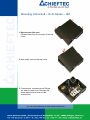
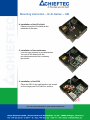
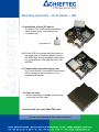
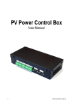
Mounting instruction – Hi-Fi-Series – HM
Specification:
Color:
black / silver
Material:
complete aluminium
Figure HM-01B:
VFD (mou
unted)
DVD cover
Open/
Close
Volume control
Power
switch
Navigator
Resset
buttton
Front connectors /
Card reader
Mounting instruction
n – Hi-Fi-Series – HM
1. How to open the case
Please loosen the four screws of the top
cover.
2. Now easily remove the top covver.
3. Components, connectors and fittings
are easy to reach now. Removve the
three g
green bolts to take out th
he
accessories.
Mounting instruction – Hi-Fi-Series – HM
4. Installation of the I/O shield
Please mount the I/O shield on
n the
backside of the case.
5. Installation of the mainboard
d
Find the right position for the mainboard
m
mainboard.
You can fix the board with the
provided screws and the necesssary
grommets.
6. Installation of the PSU
Place the PSU in the right position (as shown
on the image) and fix it with four screws.
Mounting instruction – Hi-Fi-Series – HM
7. Installation of 3,5“ HDD (only
y HM-01 / HM-02)
To install a 3,5“ HDD use the ne
ecessary
screws (Img. 1) provided in the accessory box.
Im
mg.1
g HDD Screw
8. Press the red tagged levers an
nd open the
cage
g like shown on the image.
g .
9 Now you can put the HDD upright in the
9.
HDD cage.
Mounting instruction
n – Hi-Fi-Series – HM
10. Now close the cage but be ca
areful with
the special HDD screws.
IMPORTANT! ATTENTION!!!
11. Installation of 3,5“ HDD (on
nly HM-03)
Please see step 7 first. In ord
der to mount
th HDD on the
the
th bottom
b tt
off the
the cage,
install the screws in the middle and rear
holes of the HDD. Be careful when you
e not to
slide in the HDD into the cage
touch the nearby iMON modu
ule .
12. Hold the HDD horizontally an
nd slide it
into the cage. Now switch the
e safety
hook (yellow/red arrow) to fixx the
HDD.
Mounting instruction – Hi-Fi-Series – HM
13. Installation of the 5,25“ de
evice
To install a 5
5,25
25“ ODD use the necessary
white screws (Img. 2) provid
ded in the
accessory box.
I
Img.2
2 ODD S
Screw
14. Put the ODD in the slide rails like shown on
the image and fix it with the safety hook on
g Now connecct all components,
p
,
the ODD cage.
e.g. motherboard, VGA card
d, fans etc. with
the PSU.
15. Connect the front cables of
o the case
E.g. Power Switch, Power LED,
L
Reset button,
etc. according
di to the
h instruct
i
tion
i off your
motherboard manual.
16. Close the case
When everything is installe
ed, screw the top
cover back onto the case.
Have fun with your new CHIE
EFTEC case!