1
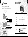
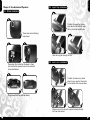
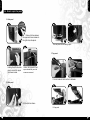
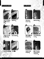
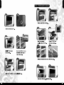
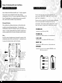
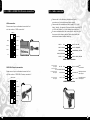
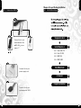
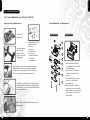
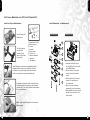
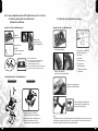
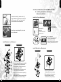
VD500LBNA
User's Manual
Benutzerhandbuch
Mode d’emploi
Manual del usuario
Manuale dell’utente
安裝說明書
用戶手冊
ユーザーズマニュアル
Руководство пользователя
C 2007 Thermaltake Technology Co., Ltd. All Rights Reserved. 2007.05
All other registered trademarks belong to their respective companies. www.thermaltake.com
Tested To Comply
With FCC Standards
FOR HOME OR OFFICE USE
English
English
TM
VD500LBNA
User's Manual
English
English
Chapter 1. Product Introduction
ontents
Specification
Chapter 1. Product Introduction
1-1
Specification
02
Chapter 2. Case Mechanical Operation
2-1
Wheel installation
03
2-2
Upper flap installation
04
2-3
Lower visor installation
04
2-4
How to open the panel
05
Model
A.Side panel
05
Case Type
Super Tower
B.Rear panel
05
Dimension
(H*W*D)
C.Top panel
06
650 x 240 x 770 mm
25.6 x 9.4 x 30.3 inch
2-5
5.25" device installation
07
Material
Aluminum Extrusion
2-6
Color
Black
HDD installation
08
2-7
How to install the Power Supply
09
2-8
PCI slot usage
09
2-9
7" LCD monitor installation (optional)
10
2-10
7" LCD monitor removal
12
Chapter 3. Motherboard & Lends Installation
3-1
Motherboard installation
13
3-2
Case LED connections
14
3-3
USB2.0 & IEEE1394 Firewire connection
15
3-4
Audio connection
16
3-5
Connexion eSATA
17
VD500LBNA
Cooling
System
Motherboards
Drive Bays
-7" Drive Bay
-5.25" Drive Bay
-3.5" Drive Bay
9.6" x 9.6" (Micro ATX), 12" x 9.6" (ATX),
12" x 13" (Extend ATX)
2
4
3 (HDD)
or
6
3 (HDD)
Front I/O
e-SATA connector x 1, USB2.0 x 2,
IEEE 1394 Firewire x 1, HD Audio
Expansion Slots
9
Chapter 4. Liquid Cooling Installation
1
4-1
Installation steps
18
4-2
Install waterblock
19
4-3
Install watertube
29
4-4
Fill Coolant
31
4-5
Schedule Maintenance
33
Liquid
Cooling
System
Application
Optional
Components
7" LCD Monitor (P/N:A2413-03)
2
English
English
2-2 Upper flap installation
Chapter 2. Case Mechanical Operation
2-1 Wheel installation
1
1
To attach the upper flap, please
align the visor flap with the hinge
tabs on top of the SwordM case.
These holes are for attaching
case wheels.
2
3
Slide the hinge bar through the visor.
2
3
2-3 Lower visor installation
Please align the 4 holes from the wheel to these
four holes on the case and screw in the wheel with
the provided screws.
1
4
To attach the lower visor, please
place the visor over the three holes
on the bottom of the case as shown.
5
Please repeat with the last three wheels.
2
3
Please screw in the visor with supplies hardware through
the three holes circled.
3
4
English
English
2-4 How to open the panel
A.Side panel
1
Remove the two screws,
the upper and lower screws on
the right side, side panel.
2
3
The rear panel should swing open.
C.Top panel
3
2
Holding the left side, side
panel, remove the upper
and lower screws.
1
Caution, the Hydraulic lift will
open automatically once the
screws are removed.
2
1
2
1
2
Pull both sides of latch and turn clockwise.
B.Rear panel
3
1
4
Pull the latch as shown.
Lift top panel.
5
6
English
English
2-5 5.25" device installation
7
2-6 HDD installation
1
2
1
2
3
4
3
4
5
6
5
6
8
English
English
2-7 How to install the Power Supply
2-9 7" LCD monitor installation (Optional)
1
2
1
2
1
Unscrew screws shown
at the top edge of the case
and remove the power
supply cage.
2
Slide the power supply into
the power supply cage.
1
4
3
Place power supply cage
back into position as shown.
Place power supply cage with
power supply as shown and
screw in to secure.
2
3
4
5
2-8 PCI slot usage
2
1
Pull the latch on the
PCI card holder.
Insert the PCI card in the
corresponding slot
2
1
Secure the latch on the
PCI card holder
3
9
10
English
English
2-10 7" LCD monitor removal
6
8
10
11
1
2
3
4
6
7
8
9
7
9
11
12
English
English
Chapter.3 Motherboard & Leads Installation
3-1 Motherboard Installation
3-2 Case LED connections
Each motherboard has different standoff layout. It is highly suggested
that you refer to your motherboard's manual when installing
motherboard into the Case. The cases are applicable with Standard ATX,
Micro ATX motherboards. Your motherboard may require a special I/O
Panel, which should be included with your motherboard.
Placement Direction:
When installing the motherboard, make sure you follow the direction
provided by your motherboard manufacturer. On most standard
motherboards, the edge with external ports goes to the rear part of the
chassis. It is highly recommended that you install CPU, heat sink and
modular components before fixing the motherboard inside the chassis.
On the front of the case, you can find some LEDs and
switch leads (POWER SW*1, POWER LED*1, H.D.D. LED*1,
RESET SW*1, SPEAKER*1).
Please consult user manual of your motherboard manufacturer,
then connect these leads to the panel header on the
motherboard. These leads are usually labeled; if not, please
trace them back to the case front to find out their source.
POWER LED
connects to your M/B at the PLED.
POWER SW
Note
Due to the variety of motherboards on the market, the majority of the
motherboards come with their own I/O plates. It s necessary for you
to remove the fan holder before install the I/O plates.
connects to the PWR connector on the motherboard.
H.D.D LED
connects to the 2-pin labeled HDD LED connector.
RESET SW
connects to the RSW connector on the motherboard.
478
SPEAKER
connector: find out the 4-pin labeled SPEAKER on the
M/B then connect it.
This side towards
the rear of the
chassis
The locations of the
screw holes. Note
these locations and
place included
standoffs on the
chassis first.
Above illustration is a sample of what the motherboard's
layout. For more detail screw hole placement, please refer
to your motherboard manual.
13
14
English
English
3-3 USB2.0 & IEEE1394 Firewire connection
USB connection
Please consult your motherboard manual to find
out the section of "USB connection".
USB2.0
(Brank)
GND1
3-4 Audio connection
Please refer to the following illustration of Audio
connector and your motherboard user manual.
Please select the motherboard which used AC'97 or HD
Audio (Azalia), (be aware of that your audio supports AC'97
or HD Audio (Azalia)) or it will damage your device(s).
On some motherboards, the connectors for Audio are not
the same as the drawing below. Please check with your
motherboard manual before installing.
GND2
Data+1
Data-1
BLACK
AUD GND
PORT1 R BROWN
BLACK
PRESENCE#
PORT2 R YELLOW
ORANGESENSE1_RETURN
PORT1 L
Data+2
Data-2
RED
SENSE_SENDPURPLE
Vcc1
KEY
Vcc 2
PORT2 L
BLUE
GREEN SENSE2_RETURN
AUDIO AZALIA Function
IEEE1394 Firewire connection
Please consult your motherboard manual to find
out the section of "IEEE1394 Firewire connection".
VG
TPB+
VP
TPA-
MIC IN
RED
NC
Front Left Channel
Audio Signal
IEEE1394a
TPA+
Front Microphone
input Signal
Front Microphone MIC POWER BROWN
Power
Front Right Channel
R-OUTYELLOW
Audio Signal
L-OUT
BLUE
BLACK
Front
GROUND
Audio Ground
NC
YELLOW R-RET
Rear Right Channel
Audio Signal
KEY
BLUE
L-RET
Rear Left Channel
Audio Signal
AUDIO AC'97 Function
(Brank)
TPB(Brank)
GND
15
16
English
English
Chapter 4. Liquid Cooling Installation
3-5 Connexion eSATA
4-1 Installation steps
Components check
Connect this to your
motherboard at the
HDD LED
arrow
means "+"
Install Waterblock
4-2-1
4-2-2
4-2-3
4-2-4
Connect this to your
P19
Intel LGA 775
Intel P4 478
AMD K8
AMD AM2
Install Water tube
P29
Fill Coolant
P31
power supply unit.
Complete installation
Connect this to your
motherboard at SATA.
17
18
English
English
4-2 Install waterblock
4-2-1 Secure Waterblock onto CPU (Intel LGA 775)
Install the Clip on Motherboard
Install Waterblock on Motherboard
Intel LGA 775
Motherboard
Tear off the tape on
the back of the
Insulator (C) and
place it on the metal
H-type clip(A).
C
B
A
E
D
I
Exploded View
J
Completed View
G
Components for LGA 775:
A-Metal H-type clip
B-Cushion
C-Insulator
D-50mm screws
E-Thumb nuts
G-Thermal compound
I -Stand offs
J -Red washers
E
A
I
G
J
B
Note: Placing the cushion onto the motherboard with the
adhesive will prevent you from removing the cushion in
the future. If you are planning to remove the cushion for
future use, please don't remove the protective tape.
Combine the Insulator(C) and the cushion (B) using
the adhesive.Stick the metal H-type clip(A) with the
insulators (BC). Tear off the protective layer to adhere
it onto the motherboard.
C
A
D
21
1.Insert the screws (D) through
the Clip(ABC) into the four holes
on the Motherboard.
2.Put the washers (J) along the
screws to prevent the electric
current.
3.Put the stand offs (I) along the
screws to fix the screws on
the motherboard.
4.Apply a thin layer of thermal
compound (G) onto the processor.
5.Place waterblock on the processor
through the screws and fix it by
thumb nuts(E).
Attach H-type clips(including ABC) on the back side
of motherboard.
19
20
English
English
4-2-2 Secure Waterblock onto CPU (Intel P4 Socket 478)
Install the Clip on Motherboard
Install Waterblock on Motherboard
Intel P4 Socket 478
Motherboard
Tear off the tape on
the back of the
Insulator (C) and
place it on the metal
H-type clip(A).
C
B
A
E
D
I
Exploded View
J
Completed View
G
Components for P4 478:
A-Metal H-type clip
B-Cushion
C-Insulator
D-50mm screws
E-Thumb nuts
G-Thermal compound
I -Stand offs
J -Red washers
E
A
I
G
J
B
Note: Placing the cushion onto the motherboard with the
adhesive will prevent you from removing the cushion in
the future. If you are planning to remove the cushion for
future use, please don't remove the protective tape.
Combine the Insulator(C) and the cushion (B) using
the adhesive.Stick the metal H-type clip(A) with the
insulators (BC). Tear off the protective layer to adhere
it onto the motherboard.
C
A
D
21
1.Insert the screws (D) through
the Clip(ABC) into the four holes
on the Motherboard.
2.Put the washers (J) along the
screws to prevent the electric
current.
3.Put the stand offs (I) along the
screws to fix the screws on
the motherboard.
4.Apply a thin layer of thermal
compound (G) onto the processor.
5.Place waterblock on the processor
through the screws and fix it by
thumb nuts(E).
Attach H-type clips(including ABC) on the back side
of motherboard.
21
22
English
English
4-2-3 Secure Waterblock onto CPU (AMD K8 Socket 754 / 939 / 940)
A. Install by back plate for motherboard
(Standard installation)
Install the Clip on Motherboard
G
Install the Clip on Motherboard
Components for
AMD K8:
G-Thermal compound
H-38mm screws
Remove the
retention frame
from motherboard.
C
B
A
AMD K8
Motherboard
H
B. Install by clips bundled in package
D
E
F
G
I
AMD K8 Motherboard
Check Your Back Plate!
A. If the back plate does have threaded
stand offs, please continue with
standard installation.(4-2-3 A)
B. If the back plate does NOT have threaded
stand offs, please continue with 4-2-3 B.
Remove the retention
module from the motherboard.
Components for AMD K8:
A-Metal H-type clip
B-Cushion
C-Insulator
D-50mm screws
E-Thumb nuts
F-White washers
G-Thermal compound
I -Stand offs
Install Waterblock on Motherboard
Exploded View
Completed View
Remove the back plate on
back side of motherboard.
H
Tear off the tape on the back of
the Insulator (C) and place it on
the metal H-type clip(A).
G
1.Apply a thin layer of thermal
compound(G) onto the processor.
2.Place waterblock on the processor.
3.Secure the waterblock on the
motherboard by using screws(H).
23
Note:
Placing the cushion onto the motherboard with the adhesive will prevent you from
removing the cushion in the future. If you are planning to remove the cushion for
future use, please don't remove the protective tape.
24
English
English
4-2-4 Secure Waterblock onto CPU (AMD Socket AM2)
A. Install by back plate for motherboard
(Standard installation)
Combine the Insulator(C) and the cushion (B)
using the adhesive. Stick the metal H-type clip(A)
with the insulators (BC). Tear off the protective
layer to adhere it onto the motherboard.
Attach H-type clips(including ABC) on the back
side of motherboard.
Install the Clip on Motherboard
AMD AM2
Motherboard
G
H
Components for
AMD AM2:
G-Thermal compound
H-38mm screws
Check Your Back Plate!
A. If the back plate does have threaded
stand offs, please continue with
standard installation.(4-2-4 A)
B. If the back plate does NOT have threaded
stand offs, please continue with 4-2-4 B.
Install Waterblock on Motherboard
Exploded View
Remove the
retention frame
from motherboard.
Completed View
Install Waterblock on Motherboard
E
Exploded View
Completed View
A
I
G
H
F
B
C
A
D
25
1.Insert the screws (D) through the Clip(ABC)
into the two holes on the Motherboard.
2.Put the washers (F) along the screws to
prevent the electric current.
3.Put the stand offs (I) along the screws to
fix the screws on the motherboard.
4.Apply a thin layer of thermal compound(G)
onto the processor.
5.Place waterblock on the processor through
the screws and fix it by thumb nuts(E).
G
1.Apply a thin layer of thermal
compound(G) onto the processor.
2.Place waterblock on the processor.
3.Secure the waterblock on the
motherboard by using screws(H).
26
English
English
B. Install by clips bundled in package
Combine the Insulator(C) and the cushion (B)
using the adhesive. Stick the metal H-type clip(A)
with the insulators (BC). Tear off the protective
layer to adhere it onto the motherboard.
Install the Clip on Motherboard
C
B
A
E
D
AMD AM2 Motherboard
Remove the retention
module from the motherboard.
F
G
I
Components for AMD AM2:
A-Metal H-type clip
B-Cushion
C-Insulator
D-50mm screws
E-Thumb nuts
F-White washers
G-Thermal compound
I -Stand offs
Attach H-type clips(including ABC) on the back
side of motherboard.
Install Waterblock on Motherboard
Exploded View
Completed View
E
A
Remove the back plate on
back side of motherboard.
I
G
F
B
Tear off the tape on the back of
the Insulator (C) and place it on
the metal H-type clip(A).
C
A
D
Note:
Placing the cushion onto the motherboard with the adhesive will prevent you from
removing the cushion in the future. If you are planning to remove the cushion for
future use, please don't remove the protective tape.
27
1.Insert the screws (D) through the Clip(ABC)
into the two holes on the Motherboard.
2.Put the washers (F) along the screws to
prevent the electric current.
3.Put the stand offs (I) along the screws to
fix the screws on the motherboard.
4.Apply a thin layer of thermal compound(G)
onto the processor.
5.Place waterblock on the processor through
the screws and fix it by thumb nuts(E).
28
English
English
4-3 Install watertube
Copper
waterblock
Use pliers to tighten the hose clips.
Repeat the steps for the other side.
Pump
Liquid
tank
Radiator
Unscrew the nut on waterblock.
29
Unscrew the nut of tank and insert
the tube from radiator through the
nut of pump. Then tighten it.
Insert a tube through the
nut of waterblock. Tighten
the nut on the waterblock.
Unscrew the nut of pump and insert
a new tube through the nut of pump.
Then tighten it.
Insert the hose clip and the
hose connector through the
tube from the waterblock.
Unscrew the nut of waterblock and
insert the tube from pump through
the nut of pump. Then tighten it.
Connect the 4-pin connector of pump
to power supply.
30
English
English
4-4 Fill Coolant
Open the cover of liquid tank and
fill the tank up with coolant.
Turn on the PC power switch.
Note:
1. If bubbles are forming within the tubing, you
may tap the tubing gently to remove them
until all are gone.
2. After installation is completed, please ensure
there are no bent tubings.
Liquid level will decrease when you
power on the system, please keep
filling coolant until the tank is filled up.
Please make sure liquid is flowing
continuously and smoothly within the
tube. Close the cover of liquid tank.
31
32
English
English
4-5 Schedule Maintenance
Performing scheduled check up for the liquid cooling system will
ensure optimal cooling performance!
Pump
Fan Assembly
Make sure fan is operating properly without abnormal noise.
Ensure pump is working proper.
Tubing
Water Tank
Tubing within the system must not be bent.
Replace tubing if necessary.
Check for water level within the water tank. If the liquid level is below the low level,
please follow the installation steps on manual to refill the coolant.
( we strongly recommend checking the water level once a month)
Note: It is recommended that coolant to be replaced once every 6 months. Depending
on the workload of the system, coolant may need to be refilled more often.
Tubing Connections
Make sure each connection is tightly secured and
that there are no sign of leakage.
33
34