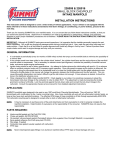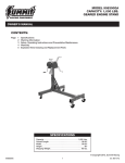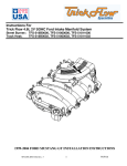
1
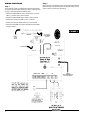
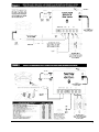
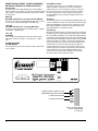
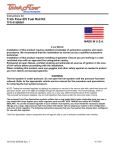
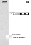
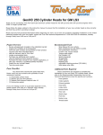
FORM #1468SUM 4/07
INSTALLATION INSTRUCTIONS
SUMMIT RACING
STREET & STRIP SPORTSMAN
CD DIGITAL IGNITION
Part No. SUM-850702
Notice: This product is legal for sale or use only on vehicles which may never be used on highways.
Summit Racing Street & Strip Sportsman CD Digital Ignition Controls are not compatible with
distributorless systems or positive ground applications. The RPM Limiter will not work properly with
odd-fire or semi-even fire V6 applications. Not designed for marine use.
GENERAL INFORMATION
Spark Plug Gaps
The RPM limiter in this ignition system is not recommended as an
engine speed governor. The use of the RPM limiters is not recommended for applications equipped with a catalytic converter.
Similarly, forcing engine RPM past the RPM limiter continuously for
long sustained intervals can cause problems resulting from fuel build
up in the exhaust system that may adversely affect the application.
For street applications, use your engine manufacturer’s specifications. For racing applications, start with your engine manufacturer’s
specifications, then experiment with the plug gap to achieve maximum performance.
Ignition Ballast Resistor/Loom Resistance Wire
Electric Welding
Disconnect the ignition system and unplug any distributor harnesses
(if possible) before any welding is done on the vehicle.
This ignition’s performance is not affected by the presence of the
factory ignition resistors or ignition ballast resistors in the wire from
the ignition switch. It is not necessary to install ignition ballast resistors as specified by the instructions for the particular distributor.
Ignition Coils
This ignition system is designed to work with the Summit Racing
Street & Strip Ignition Coil (Part No. SUM-850510). Avoid using any
other type of ignition coil.
Spark Plug Wires
YOU MUST USE suppression type (carbon core, spiral core) spark
plug wire. We recommend spiral core ignition wire. Suppression type
spark plug wires prevent false triggering and the possibility of
premature ignition or accessory failures.
DO NOT USE solid core (copper core; stainless steel core) spark
plug wire with any electronic ignition system or accessory. Solid
core spark plug wire is a source of ignition noise, which can cause
false triggering and premature ignition or accessory failure.
MOUNTING PROCEDURE
Step 1
Disconnect the battery (–) cable to cut power to the system.
Step 2
Select a convenient location to mount the ignition system. Keep the
unit away from hot engine components or extreme heat such as the
exhaust system and manifolds. Keep the unit away from moving
devices, such as fans, belts and linkages. The location must be dry.
Moisture will damage components inside the unit.
Step 3
Mounting to a flat surface with shock mounts
• Hold the unit in its mounting position and center punch the
mounting pattern on the mounting surface for drilling mounting
holes. Drill mounting holes using a 9/32" drill bit.
• Install the shock mounts into the bottom plate of the unit. Hold the
unit in position where it will be mounted.
• From the backside of the mounting surface, insert the washers and
the 1/4-20 nylock nuts onto the shock mount studs. Tighten each
nut until snug.
1
WIRING PROCEDURE
Step 2
Step 1
When wiring the Summit Racing Street & Strip Sportsman CD Digital
Ignition System to an electronic ignition or magnetic pickup, refer to
Figures 2 and 3, and trace wires for hookup.
Ensure that your vehicle is equipped with a ground cable between
the engine block and firewall (10 gauge or larger is required). Refer
to Figure 1 while performing the following steps.
• Connect the HEAVY RED wire to the 12-volt battery (+) post or
battery (+) terminal on the starter solenoid.
• Connect the HEAVY BLACK wire to engine or chassis ground.
• Connect wires between the COIL (+) and (–) terminals.
• Connect 12-volts from ignition switch to the +12V terminal.
• Connect the tach/RPM sensing wire and optional external RPM
control to sockets.
FIGURE 1
2
3
SUMMIT RACING STREET & STRIP SPORTSMAN
CD DIGITAL IGNITION TOP PANEL CONTROLS
Basic Operation
The top panel has a three-digit LED display, three LED indicators,
and three switches. The switches are used to set the mode and mode
values, and the 3 separate LEDs indicate the mode. The four modes
are listed below:
RPML LED
Main RPML (normally used as an engine protection RPM limit)
This value is valid as long as another RPM limit has not been selected. The range is 1,000 to 12,000 RPM, in 100 RPM steps.
“AUX” LED
Aux RPML2 (normally used as a launching RPM control)
This value, if selected, overrides the main RPML. Range is 1,000 to
12,000 RPM, in 100 RPM steps.
“RET” LED
HS RETARD1
This is a high-speed retard function which will retard the engine
timing when selected. The range is 1 to 15 degrees in .1 degree
steps.
ALL MODE LEDs BLANK
CYLINDER NUMBER
This function allows you to select the engine cylinder number from
4 to 12 cylinders.
Setting Mode and Values
To adjust one of the modes, press the "MODE" switch until the
proper mode LED is lit (or none are lit, if you're selecting the
cylinder mode), then use the arrow keys to increase or decrease
the value. If you go past one end of the mode range, the display
will start over at the other end. For example, if you continue to
increase the RPML value past 12,000, the display will start over
at 1,000 RPM.
Start Retard
The Summit Racing Street & Strip Sportsman CD Digital Ignition has
a built-in automatic start retard. This automatically retards the engine
timing below 500 RPM. The retard increases to 20 degrees at 100
RPM. Below 100 RPM, the retard is fixed at 30 milliseconds, and
above 500 RPM there is no automatic retard.
Activation Plug
Although the activation plug has 8 contacts, only two are used on the
Summit Racing Street & Strip Sportsman CD Digital Ignition: RPML2
for the Aux RPML, and HSRET 1 for the High-Speed Retard function.
If you add the optional Summit Racing Street & Strip 3R/3R Upgrade
Controller Part No. SUM-850708, all other functions except the RPM
switch relay contacts are available. The plug has clamp-type terminals that will accept up to 14 gauge wire (stranded is preferred, but
solid will work). Insert the wire into the clamp, then tighten the
screw to hold the wire in place. The plug also has screws at each
end to firmly fasten to the socket on the ignition’s circuit board. Do
not overtighten these screws. Each RPML or Retard function
requires 12 volts to activate. Typical methods are clutch switch,
trans-brake switch, nitrous solenoid, or similar.
SUMMIT RACING STREET & STRIP
SPORTSMAN CD DIGITAL IGNITION
+12 VOLTS TO ACTIVATE
+12 VOLTS TO ACTIVATE
NC
C
NO
RPM2
RPM3
RET1
*RET2
*RET3
*Only used when optional
Part No. SUM-850708
is connected.
4
Summit Racing Street & Strip
Sportsman CD Digital Ignition Warranty
Summit Racing Equipment warrants this product for 1 year from date
of purchase. If used for racing or competition, this warranty is limited
to manufacturer defects only; wear and breakage are not covered
under any circumstances.
If the product shows, in our opinion, evidence of being used or
installed contrary to the instructions and/or subjected to improper
handling, packaging, or shipping by the customer, it will not be
covered by our limited warranty.
Summit Racing Equipment’s liability for losses or damages, arising
out of any cause whatsoever, is limited to full refund of the purchase
price or, at our option, repair or replacement of the product(s).
Summit Racing Equipment shall not be liable for any consequential
or incidental damages. Some states do not allow exclusion or
limitation of consequential or incidental damages, so the above
limitation or exclusion may not apply to you.
SUMMIT RACING EQUIPMENT
1200 SOUTHEAST AVENUE
TALLMADGE, OHIO 44278
800.230.3030
FORM #1468SUM
4/07
5