1
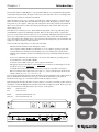
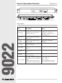
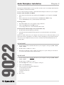
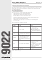
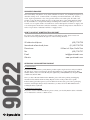
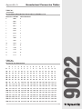
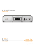
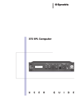
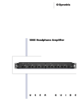
9022 User’s Guide
9022 2x2 DSP Engine
Table of Contents
Introduction
1
Chapter 2
Operator Safety Summary
2
Chapter 3
Hardware Installation
3
Chapter 4
Front & Rear Panel Controls
4
Chapter 5
Audio Workplace Installation
8
Chapter 6
Using Audio Workplace
10
Chapter 7
Specifications
17
Chapter 8
Block Diagram
18
Chapter 9
Warranty & Service
19
Appendix A Hexadecimal Conversion Tables
21
Appendix B Declaration of Conformity
23
9022
Chapter 1
Rev A.03, 2 March, 2000
Symetrix part number 5390220A03
Subject to change without notice.
©2000, Symetrix, Inc. All right reserved.
Symetrix is a registered trademark of Symetrix, Inc.
Mention of third-party products is for informational
purposes only and constitutes neither an endorsement
nor a recommendation. Symetrix assumes no responsibility
with regard to the performance or use of these products.
Under copyright laws, no part of this manual may be
reproduced or transmitted in any form or by any means,
electronic or mechanical, including photocopying,
scanning, recording or by any information storage and
retrieval system, without permission, in writing, from
Symetrix, Inc.
i
6408 216th St. SW
Mountlake Terrace, WA 98043
Tel (425) 778-7728
Fax (425) 778-7727
Email: [email protected]
Chapter 1
Introduction
The Symetrix 9022 2x2 DSP Engine is a programmable DSP processor intended for the installed
sound market. Symetrix Audio Workplace software provides real-time control over multiple audio
functions from a Windows 95/98 PC environment.
Audio Workplace allows you to configure, program presets, adjust parameters, or download new
DSP code in the field. The 9022 has a minimal front panel; Audio Workplace provides a virtual
front panel via your computer. After setup and configuration, the settings remain stored inside the
9022’s non-volatile memory. The virtual front panel disappears with your PC. This leaves the
chassis tamper-proof.
The 9022 is a two-channel processor. Each channel has EQ, high- and low-pass filtering, delay,
and multiband compression and limiting available. There are two inputs and two outputs. The
processor’s user interface imitates a dual-row, 8-slot card frame. The highly intuitive user interface
allows you to drag and drop processor blocks into the frame, and to interconnect them. Don’t
worry about what works and what doesn’t; the software has been designed to prevent mistakes and
simply won’t allow an incorrect interconnection.
You’ll need the following items to use and control the 9022:
The 9022 and the Symetrix Audio Workplace software.
A PC computer running the Microsoft Windows 95 or 98 graphical operating system. The
computer must have an unused serial (COM) port. If you’re starting from scratch, install
Windows first, and make sure that it is running before trying to install the Audio Workplace
software.
·
Processor requirements are determined by your version of the Windows operating system.
·
You should have at least 16 Mb of RAM.
·
You need at least 2 Mb of free space on the computer’s hard drive.
·
The display subsystem should use at least 64K colors (also known as 16-bit high-color) and
should also be set to use small fonts.
·
A suitable interconnect cable from the computer’s serial port to the 9022’s front-panel
RS-232 connection. The cable needs to have pins 2, 3, 4, and 5 wired between the male and
female connectors (2 to 2, 3 to 3, 4 to 4, 5 to 5).
You can install and run the Symetrix Audio Workplace software without having a 9022 connected.
Refer to the Hardware Installation section (pg. 3) to install the 9022. Refer to the Software
Installation section (pg. 8) to install the Symetrix Audio Workplace software.
This printed guide describes the 9022’s features and how to install it. For further product and usage
information, consult the HELP menu available in the Audio Workplace program. Please report any
bugs or inconsistencies with the hardware, the software, or this guide to:
Phone:
Fax:
Email:
Web site:
(425) 778-7728
(425) 778-7727
[email protected]
www.symetrixaudio.com
PRESET
SYSTEM STATUS
CH1
TM
AUDIO WORKPLACE
9022
2X2 DSP ENGINE
CLIP
RS-232 CONTROL
CH2
1
2
3
4
SIGNAL
SIGNAL
5
6
BYPASS
BYPASS
7
8
POWER
COMM
CLIP
INPUT
Front panel
CH2 OUTPUT
TM
REMOTE PROGRAM SELECT
1 2
3 4
5 6
7 8
9022 AUDIO WORKPLACE
CONNECT TO
SYMETRIX PS3 OR
PS3E POWER
SUPPLY ONLY.
SLAVE PORT
CH2 INPUT
CH1 INPUT
CH2 IN
CH1 IN
AUDIO WORKPLACE
TM
9022
2X2 DSP ENGINE
1
FABRIQUÉ AUX E.-U. PAR SYMETRIX INC., LYNNWOOD, WASHINGTON.
RÉFÉREZ TOUTE RÉPARATION À UN TECHNICIEN QUALIFIÉ.
CH1 OUTPUT
CH2 OUT CH1 OUT
DEVICE
ADDRESS
HOST PORT
DOWNSTREAM
UPSTREAM
2
3
4
5
6
7
8
MANUFACTURED IN
LYNNWOOD, WA, USA
THIS UNIT CONTAINS NO
USER SERVICEABLE PARTS
Rear panel
1
9022
·
·
Operator Safety Summary
Equipment Markings
CAUTION
RISK OF ELECTRIC SHOCK
DO NOT OPEN
TO REDUCE THE RISK OF FIRE OR
SHOCK DO NOT EXPOSE
WARNING: ELECTRIC
THIS EQUIPMENT TO RAIN OR MOISTURE
DE CHOC ELECTRIQUE
AVIS: RISQUE
NE PAS OUVRIR
SEE OWNERS MANUAL. VOIR CAHIER D’INSTRUCTIONS.
No user serviceable parts inside. Refer servicing to qualified service personnel.
Il ne se trouve a l’interieur aucune piece pourvant entre reparée l’usager.
S’adresser a un reparateur compétent.
The lightning flash with arrowhead symbol within an
equilateral triangle is intended to alert the user of the
presence of uninsulated “dangerous voltage” within
the product’s enclosure that may be of sufficient
magnitude to constitute a risk of electric shock to
persons. The exclamation point within an equilateral
triangle is intended to alert the user of the presence of
important operating and maintenance (servicing)
instructions in the literature accompanying the product
(i.e. this manual).
Caution To prevent electric shock, do not use the
Terms
polarized plug supplied with the unit with
any extension cord, receptacle, or other
outlet unless the blades can be fully
inserted.
9022
Several notational conventions are used in this
manual. Some paragraphs may use Note, Caution,
or Warning as a heading. Certain typefaces and
capitalization are used to identify certain words.
These are:
Note
Caution
Warning
CAPITALS
Boldface
2
Identifies information that needs
extra emphasis. A Note generally
supplies extra information to help
you to better use the 9022.
Identifies information that, if not
heeded, may cause damage to the
9022 or other equipment in your
system.
Identifies information that, if
ignored, may be hazardous to your
health or that of others.
Controls, switches or other markings
on the 9022’s chassis.
Strong emphasis.
Chapter 2
Important Safety Instructions
Please read and keep these instructions. Heed
and follow all warnings and instructions.
Install in accordance with the manufacturer’s
instructions.
Grounding The chassis of this product is
grounded through the grounding conductor of the
PS-3/PS-3E power cord. To avoid electric shock,
plug the power cord into a properly wired
receptacle before making any connections to the
product. A protective ground connection, by way
of the grounding conductor in the power cord, is
essential for safe operation. Do not defeat the
safety purpose of the grounding plug. The
grounding plug has two blades and a third
grounding prong. The third prong is provided for
your safety. When the provided plug does not fit
your outlet, consult an electrician for replacement
of the obsolete outlet.
Danger from Loss of Ground If the protective
ground connection is lost, all accessible conductive parts, including knobs and controls that may
appear to be insulated, can render an electric
shock.
Proper Power Cord Use only the power cord
and connector specified for the product and your
operating locale. Use only a cord that is in good
condition. Protect the power cord from being
walked on or pinched, particularly at plugs,
convenience receptacles, and the point where
they exit from the apparatus.
Operating Location Do not operate this
equipment under any of the following conditions: explosive atmospheres, in wet locations,
in inclement weather, improper or unknown AC
mains voltage, or if improperly fused. Do not
install near any heat source such as radiators, heat
registers, stoves, or other apparatus (including
amplifiers) that produce heat. Unplug this
apparatus during lightning storms or when
unused for long periods of time.
Stay Out of the Box To avoid personal injury
(or worse), do not remove the product covers or
panels. Do not operate the product without the
covers and panels properly installed. Only use
accessories specified by the manufacturer. Clean
only with a damp cloth.
User-serviceable parts There are no user
serviceable parts inside the 9022. In case of
failure, refer all servicing to the factory. Servicing is required when the 9022 has been damaged
in any way, such as when a power supply cord or
plug is damaged, liquid has been spilled or
objects have fallen into the apparatus, the
apparatus has been exposed to rain or moisture,
does not operate normally, or has been dropped.
Chapter 3
Hardware Installation
1.
Provide sufficient rackspace. Avoid situating the 9022 next to wireless microphone
receivers (just in case). No extra rackspace is required between adjacent 9022’s.
2.
Use the appropriate Symetrix PS-3 AC power transformer for your locale’s mains voltage.
Accept no substitutes. “Similar-looking” is not close enough to guarantee compatibility.
3.
Make the audio input and output connections as required.
4.
The balanced input stage uses a simple diffamp circuit. For unbalanced operation, ground the
low side of the input, preferably at the source.
5.
The balanced output stage emulates a grounded-center tap transformer. For unbalanced
operation, float the unused output.
6.
If you are using multiple units with one control path, daisy chain the rear-panel Host and
Slave port connectors to each other. Do not loop the last device back to the first one. All
signal lines within the connector are passed through the 9022 for compatibility with other
non-Symetrix units. The Host and Slave port connectors are male to female connectors, like
numbered pins wired together. For a 9022-only system, only pins 2, 3, 4, and 5 are needed. If
there are other non-Symetrix devices in the chain of devices, then you may need to wire the
remaining pins together. The 9022 passes connections through on all other pins (i.e. they’re
wired together).
7.
Connect the first 9022’s Host port connector to the computer used for device control. You
can also use the front-panel connector.
8.
Set each 9022’s device address switch to something unique. We suggest starting at 1 and
incrementing the address by 1 for each additional device. The switches require a binary
number that represents the device address (convert the decimal device address to binary) in
binary notation. (See Appendix A).
9.
Connect the Remote Program Select terminals as required. A momentary ground connection
is required. This could be an SPST switch, a transistor pulldown, etc. These connections are
not required for operation. If not used, leave them (or unused terminals) unconnected.
9022
Installing the 9022 is straightforward.
3
Front & Rear Panel Controls
Chapter 4
PRESET
SYSTEM STATUS
CH1
TM
AUDIO WORKPLACE
9022
2X2 DSP ENGINE
2
CLIP
3
4
SIGNAL
SIGNAL
5
6
BYPASS
BYPASS
7
8
POWER
COMM
CH2 OUTPUT
TM
REMOTE PROGRAM SELECT
1 2
3 4
5 6
7 8
9022 AUDIO WORKPLACE
CONNECT TO
SYMETRIX PS3 OR
PS3E POWER
SUPPLY ONLY.
SLAVE PORT
CLIP
CH1 OUTPUT
INPUT
CH1 INPUT
CH2 INPUT
CH2 OUT CH1 OUT
DEVICE
ADDRESS
HOST PORT
CH2 IN
CH1 IN
AUDIO WORKPLACE
TM
9022
2X2 DSP ENGINE
1
FABRIQUÉ AUX E.-U. PAR SYMETRIX INC., LYNNWOOD, WASHINGTON.
RÉFÉREZ TOUTE RÉPARATION À UN TECHNICIEN QUALIFIÉ.
RS-232 CONTROL
CH2
1
DOWNSTREAM
2
3
4
5
6
7
MANUFACTURED IN
LYNNWOOD, WA, USA
THIS UNIT CONTAINS NO
USER SERVICEABLE PARTS
8
UPSTREAM
9022
FRONT PANEL
4
Ite m
De scription
Note s
PRESET LEDS
Identifies the preset configuration
currently in operation.
Rear panel contact closure
connections or the Audio
Workplace software select the
configuration in use.
SYSTEM STATUS
LEDS
Tells at a glance what is going on
inside the box.
CLIP LEDS
Indicates signal clipping anywhere
within the 9022.
SIGNAL LEDS
Indicates signal presence at the output
of the A/D converter.
BYPASS LEDS
Indicates BYPASS status of signal
processor.
POWER LED
Indicates presence of electrical
power.
COMM LED
Flickers during data exchange via an
RS-232 control port.
RS-232 CONTROL
DB-9 female connector. Connect host
computer here to control front panel
settings.
Control signals introduced via this
port affect only downstream 9022s.
This LED should NEVER
illuminate.
Pin 2 - RXD out
Pin 3 - TXD in
Pin 4 - DTR in, Pin 5 - ground
All other pins are not needed.
REAR PANEL
De scription
Note s
EXTERNAL POWER
INPUT
DIN-7 female connector for power
input. Use only the Symetrix PS-3 AC
power supply. Other similar-looking
“power adapters” may damage the
9022.
SLAVE PORT
(DOWNSTREAM)
DB-9 male connector. Sends RS-232
control signals to downstream units.
All signal lines passed through for
compatibility with non-Symetrix
RS-232 controlled units. See table
on page 7.
HOST PORT
(UPSTREAM)
DB-9 female connector. Accepts
RS-232 control signals from Host
computer or upstream signal
processor.
All signal lines passed through for
compatibility with non-Symetrix
RS-232 controlled units. See table
on page 7.
REMOTE PROGRAM
SELECT
Euroblock connector for remote
program control. Momentarily
grounding any of the remote program
select connections causes the 9022 to
load and execute that preset program.
DEVICE ADDRESS
dipswitch
8-way dipswitch. This switch
S1: up = 38400 baud, down =
determines the device address for this 19200 baud. 8 bits, no parity, 1
9022. Each 9022 in a controlled
stop bit.
chain must have a unique address.
Switch 1 changes the baud rate
S2-8: The address range is 1-126.
(speed) of the RS-232 interface from The switches require converting the
19200 to 38400 baud. Switches 2-8
address into a binary number (see
affect the address.
Appendix A).
CH 2 OUTPUT
XLR3-M connector. Supplies
balanced line-level output signals
from a 320-ohm source impedance.
Pin 2 is hot. The maximum output
level is +25 dBu.
CH 2 OUT
3-circuit Euroblock connector.
Paralleled with XLR3 output
connector.
CH 1 OUT
3-circuit Euroblock connector.
Paralleled with XLR3 output
connector.
9022
Ite m
The output stage emulates a
grounded center-tap transformer
winding. For unbalanced usage,
float pin 3, and remember that
you’ll lose 6 dB signal level and
output headroom.
(Table continued on next page.)
5
9022
6
CH 1 OUTPUT
XLR3-M connector. Supplies
balanced line-level output signals
from a 320-Ohm source impedance.
Pin 2 is hot. The maximum output
level is +25 dBu.
The output stage emulates a
grounded center-tap transformer
winding. For unbalanced usage,
float pin 3, and remember that
you’ll lose 6 dB signal level and
output headroom.
CH 2 INPUT
XLR3-female connector. Accepts
balanced or unbalanced line-level
signals. The input impedance is 20kilohms balanced. The maximum input
level is +25 dBu. This connector
should be driven from a lowimpedance source for best CMR
rejection.
The input stage is a simple
differential amplifier.
For unbalanced sources, connect
the minus (pin 3) connection to
ground (pin 1), preferably at the
source.
CH 2 IN
3-circuit Euroblock connector.
Paralleled with XLR3 input
connector.
CH 1 IN
3-circuit Euroblock connector.
Paralleled with XLR3 input
connector.
CH 1 INPUT
XLR3-female connector. Accepts
balanced or unbalanced line-level
signals. The input impedance is 20kilohms balanced. The maximum input
level is +25 dBu. This connector
should be driven from a lowimpedance source.
The input stage is a simple
differential amplifier.
For unbalanced sources, connect
the minus (pin 3) connection to
ground (pin 1), preferably at the
source.
Host Port Connections
The Host (upstream) port uses a DB-9 female connector with the following connections:
Pin Numbe r
Assignme nt
9022 Usage
1
CD out
pass through
2
RXD out
yes
3
TXD in
yes
4
DTR in
sense only
5
Circuit ground
yes
6
DSR out
pass through
7
RTS in
pass through
8
CTS out
pass through
9
RI out
pass through
9022
Slave Port Connections
The Slave (downstream) port uses a DB-9 male connector with the following connections:
Pin Numbe r
Assignme nt
9022 Usage
1
CD in
pass through
2
RXD out
yes
3
TXD out
yes
4
DTR out
yes
5
Circuit ground
yes
6
DSR in
pass through
7
RTS out
pass through
8
CTS in
pass through
9
RI in
pass through
7
Audio Workplace Installation
Chapter 5
The Symetrix AudioWorkplace software provides real-time control over multiple audio functions
from a Windows 95/98 PC environment.
Use one of the following procedures to install the Audio Workplace software on your computer.
From the Audio Workplace CD-ROM:
1.
The software should autorun after inserting the CD-ROM into your computer’s CD-ROM
drive.
2.
If the software does not autorun, then Click on the Start button, Run d:\setup
(if your CD-ROM drive isn’t d:, then substitute its drive letter)
From floppy discs:
1.
Insert disk number 1 into your computer’s floppy disk drive.
2.
Click on the Start button, then Run a:\setup
(if your floppy drive isn’t a:, then substitute its drive letter)
From the Symetrix Website (http://www.symetrixaudio.com):
1.
Download the Audio Workplace program file.
2.
From the Start button, Run the file/program that you just downloaded to start the Setup
program.
If there is no 9022 connected to your computer, the software reverts to offline mode. Here you can
explore the software, experiment to your heart’s content, and perhaps even get useful work done.
You can save any configurations that you create to a file that can be downloaded later into an
operating 9022.
9022
OFFLINE MODE
1.
Use the control panel to determine the name of your computer’s serial port (COM1, COM2,
COM3, COM4).
2.
Double click on “s9022.exe” to run it.
3.
When the program fails to detect a 9022 on its serial port, it opens a dialog box and asks if
you want to work offline. Click on the Yes button.
ONLINE MODE
1.
Use the control panel to determine the name of your computer’s serial port (COM1, COM2,
COM3, COM4).
2.
Double click on “s9022.exe” to run it.
3.
From the Setup menu, select your computer’s serial port.
4.
Click on the ONLINE button.
5.
Choose an option from the buttons displayed:
a. Create New Location File
b. Upload from Devices
c. Download to Devices
d. Cancel
6.
Get to work.
8
The button options are:
Create New Location File
Start New Location file. When you are done, be sure to save
it. Since you’re working online, your work is communicated
to the 9022 as you work.
Upload from Devices
Upload the location file information FROM the currently
connected 9022(s).
Download to Devices
Download the current location file to the 9022(s). Use this
option if you’ve been working offline and want to hear the
results of your work.
Cancel
Didn’t want to do this. Get me out of here.
FINDING YOUR SERIAL (COM) PORT
The 9022 requires a serial port on the host computer for communications.
1.
Click Start, Settings, Control Panel.
2.
From the Control Panel screen, locate the System icon and left-doubleclick it.
3.
Select the Device Manager tab.
4.
Locate the Ports icon and left-doubleclick it.
5.
The device manager now displays the ports used by the computer and their assignments.
Clicking on any of them displays additional information. If you have a modem, you may need
to go back to step 4, locate the Modems icon, and doubleclick it to see its COM port
assignment. Sometimes your mouse may also use a serial port.
9022
Remember the port number of an unassigned serial port for use with the 9022.
9
Using Audio Workplace
Chapter 6
SYMETRIX AUDIO WORKPLACE SOFTWARE
The Symetrix Audio Workplace is a Windows 95/98 application designed to configure and control
the 9022. Most of the software is self-explanatory, especially if you have any experience with
other Windows applications.
Device Configuration Screen
This screen allows you to configure the signal path within the 9022.
·
Click and drag any processor to the single-line diagram.
·
Click and drag any connecting line to alter the signal path.
·
Remember that there are only two inputs and two outputs.
·
The Device Configuration Screen will refuse to allow any connection that is ‘illegal.’
·
Only one split (two inputs paralleled) is allowed.
·
Think about the order of processing as you would if you were connecting physical
processors together.
Try it. It’s much easier to do than it is to describe.
9022
Fe ature
Usage
Note s
ONLINE
Connect to a 9022.
You’ll be prompted for:
Create New Location File
Upload Audio Workplace from
9022.
Download current configuration to
9022.
OFFLINE
Edit without an active connection to a
9022.
PINK NOISE
Enables an internal pink noise source
as an input signal. Separate on/off
controls are provided for each
channel, and there is an overall level
control.
DEVICE
Shows the device name, ID number.
Device name and ID number are
editable. Pick a name that is
meaningful to you.
Use the Edit Device List command
(Edit menu) to change the device
ID number associated with a
particular device..
PRESET
Edits or selects preset name in online
or offline mode.
Presets may also be named via this
dialog box.
(Table continued on next page.)
10
Virtual block diagram that displays
the current configuration.
Left click on processing blocks and
then drag and drop them into the
diagram. Click and drag between the
dots in the signal paths to change the
signal flow.
CONFIGURATION
EDITOR
Double click on any processor to edit
its settings once it is in the chain. The
MASTER buttons on the processors
make its settings the master control
for both processing blocks.
You can put several processing
blocks of the same type (like both
equalizers) into the same signal
path.
You cannot mix inputs.
The Pink LED illuminates when the
pink noise source is enabled.
The Bypass button places that channel The bypass configuration can be
of the 9022 into bypass mode. This
condition is the same as during power altered via circuit board jumpers.
off.
INPUT LEVEL
METER
Adjusts the analog input gain of each
input of the 9022.
Displays the input signal level after
the input level slider. The meter is
calibrated in dBFS; decibels relative
to full-scale (converter overload).
GAIN REDUCTION
METER
Displays the amount of gain reduction
taking place within the
compressor/limiter blocks.
OUTPUT LEVEL
SLIDER
Adjusts the analog output gain of each
output of the 9022.
This control is always displayed,
regardless of the processor block
being edited.
Another way to look at the meters
is as a headroom meter. When you
illuminate the 0dBFS segment,
you're out of headroom.
This control is always displayed,
regardless of the processor block
being edited.
9022
INPUT LEVEL
SLIDER
This control is always displayed,
regardless of the processor block
being edited.
This control is always displayed,
regardless of the processor block
being edited.
OUTPUT LEVEL
METER
MINI DEVICE
CONFIGURATION
DIAGRAM
Displays the input signal level after
the output level slider. The meter is
calibrated in dBu; decibels relative to There is also a clip LED that
0.775V RMS.
diplays for 3 seconds seconds
anytime that clipping occurs in any
of the internal modules.
Located in the lower right of the
display, this diagram allows you to
easily access any other processing
This block is always displayed,
block in the 9022. Clicking on any
regardless of the processor block
box in the diagram takes you to that
being edited.
block’s screen. Clicking on the EDIT
button returns you to the Configuration
Editor.
11
Graphic Equalizer Screen
The equalizer block can be either a 31-band graphic equalizer or a 10-band parametric equalizer.
The high- and low-pass filters are also integral to these processing blocks. The two different
equalizer types are mutually exclusive: you can’t use the graphic EQ and then switch to the
parametric EQ to notch something as well. You can cascade the two equalizer blocks and set one
as a graphic and the other as a parametric.
9022
The frequency response graph shows the cumulative effects of the equalizer and the high- and lowpass filters.
Fe ature
Usage
ONLINE
Allows you to work online (realtime)
if there is a 9022 connected.
OFFLINE
Allows you to work on a
configuration without an active
connection to a 9022.
BYPASS
Bypasses the equalizer.
FLAT
Restores controls to flat frequency
response setting.
NARROW BW
Sets filter bandwidth to
approximately 1/4 octave.
WIDE BW
Sets filter bandwidth to
approximately 4/10 octave.
GRAPHIC/
PARAMETRIC
Selects graphic equalizer or
parametric equalizer.
HIGHPASS FILTER
If enabled via the Device
Configuration screen, the highpass
filter has a 12 or 24 dB/octave slope,
and a frequency range of 20Hz 20khz.
LOWPASS FILTER
If enabled via the Device
Configuration screen, the lowpass
filter has a 12 or 24 dB/octave slope,
and a frequency range of 20Hz 20khz.
EQUALIZER SLIDERS
12
Sets boost or attenuation of a
particular band.
Note s
.
Sharp, resonate filters.
Gentle, low resonance filters.
Click and drag a slider to change
its setting.
Click on a slider, then use the up
and down arrow keys to change its
setting.
You can left-click on a dot in the
graph area of the screen and drag
that dot to set a particular control.
You can right-click in the graph
area and ‘draw’ a curve using the
mouse.
Parametric Equalizer Screen
The equalizer block can be either a 31-band graphic equalizer or a 10-band parametric equalizer.
The high- and low-pass filters are also integral to these processing blocks. The two different
equalizer types are mutually exclusive: you can’t use the graphic EQ and then switch to the
parametric EQ to notch something as well. You can cascade the two equalizer blocks in the device
configuration screen and set one as a graphic and the other as a parametric.
The frequency response graph shows the cumulative effects of the equalizer and the high- and lowpass filters.
Usage
ONLINE
Allows you to work online (realtime)
if there is a 9022 connected.
OFFLINE
Allows you to work on a
configuration without an active
connection to a 9022.
EQ BYPASS
Bypasses the equalizer.
FLAT
Restores controls to flat frequency
response setting.
INDIVIDUAL BAND
CONTROLS:
There are 10 bands, each with the
same frequency range.
BYPASS Bypasses this band of the equalizer.
Note s
There are individual per-band
bypass buttons too.
You can left-click any dot in the
display area to drag and drop it for
setting.
9022
Fe ature
Don’t confuse this with the EQ
Bypass button located in the upperleft corner of the screen.
F Sets the center frequency of this band.
BW Sets the bandwidth of this band.
GN Sets the gain of this band.
GRAPHIC/
PARAMETRIC
Selects graphic equalizer or
parametric equalizer.
HIGHPASS FILTER
If enabled via the Device
Configuration screen, the highpass
filter has a 12 or 24 dB/octave slope,
and a frequency range of 20Hz 20khz.
LOWPASS FILTER
If enabled via the Device
Configuration screen, the lowpass
filter has a 12 or 24 dB/octave slope,
and a frequency range of 20Hz 20khz.
This is the boost/cut knob.
13
Delay Screen
9022
The delay implements a single-input, single-output digital delay. You can enter the delay time in
seconds, feet, or meters.
Fe ature
Usage
ONLINE
Allows you to work online (realtime)
if there is a 9022 connected.
OFFLINE
Allows you to work on a
configuration without an active
connection to a 9022.
DELAY BYPASS
Bypasses the delay module.
DELAY SLIDER
Drag this slide control to set the
delay time.
FEET (INPUT BOX)
Type in the delay time in feet.
METERS (INPUT
BOX)
Type in the delay time in meters.
SECONDS
Type in the delay time in seconds.
ENVIRONMENT
WINDOW
Since the speed of sound is dependent
No, the 9022 does not have
on temperature, this window allows
temperature sensors within.
you to supply your own values.
14
Note s
Indicated value does not include
1.5mS propagation delay (time
required for A/D and D/A
conversion).
Compressor/Limiter Screen
The compressor/limiter implements a single- or dual-band gain reduction processor.
If the Master button has been pressed in the Device Configuration Screen block diagram, the
sidechains (gain reduction signal) of the two compressors operate using a signal representing the
sum of the two inputs.
If you want both compressors (A and B) to have the same settings, yet be independently settable,
start with the Master button pressed on the Device Configuration Screen. Make your initial settings
on the Master device, then return to the Device Configuration Screen and unclick the Master button
for the compressors.
Usage
Note s
ONLINE
Allows you to work online (realtime)
if there is a 9022 connected.
OFFLINE
Allows you to work on a
configuration without an active
connection to a 9022.
COMP/LIM BYPASS
Bypasses the compressor block.
BAND SPLIT
FREQUENCY SLIDER
Sets the frequency division between
the two bands of the
compressor/limiter when using the
split-band mode.
FULL RANGE
Selects full range mode. This is a
traditional compressor/limiter device
only. Only the controls on the righthand side of the screen are active in
this mode.
SPLIT BAND
Selects split-band mode. In this mode,
a crossover (highpass and lowpass
Split-band mode can be very
filters with inputs paralleled) drives
effective in preventing audible
separate compressor/limiter
compression artifacts.
processors, whose outputs are then
mixed back into a single signal.
GAIN SLIDER
Adjusts output makeup gain.
GRAPH AREA
Displays input/output graph
illustrating current knee, threshold,
and ratio settings.
You can drag and drop the green
dot in the input/output graph to set
the threshold. Then you can drag
the green dot at the right-end of the
graph line to set the ratio.
KNEE BUTTONS
Selects knee characteristic: soft,
medium, hard.
The knee describes the shape of the
compression curve as the signal
level transits through the threshold
level.
9022
Fe ature
(Table continued on next page.)
15
ATTACK TIME
SLIDER
Sets the attack time of the
compressor.
Longer attack times retain highfrequency transient content.
RELEASE TIME
SLIDER
Sets the release time of the
compressor.
Slower release times minimize
pumping.
THRESHOLD SLIDER
Sets the threshold level of the
compressor.
9022
RATIO SLIDER
16
Sets the compression ratio.
Generally, ratios less than 10:1 are
considered compression, while
those above 10:1 are considered
limiting.
Chapter 7
Specifications
SPECIFICATIONS
Analog to Digital Conversion
Physical
Dynamic Range
THD+Noise
Size (hwd)
Weight
>114 dBFS, A-weighted
< .002% THD @ -1dBFS, 1KHz,
input attenuators set to unity gain
Input Impedance
>20k balanced
Maximum Input Level
+25dBu balanced
Minimum Recommended Nominal Input Level
-10dBu balanced,
Minimum CMR
40dB at 60Hz
1.75 x 19 x 6 inches, 4.44 x 48.26 x 15.24 centimeters
4.4 lbs (1.99 kg) net
Electrical
Power requirements
Digital to Analog Conversion
Dynamic Range
THD+Noise
Output Impedance
>112 dBFS, A-weighted
<.003% at -1 dBFS, 1kHz,
output attenuators set to unity gain
300 Ohms balanced
115V AC nominal, 105 to 125V AC
50 to 60Hz, 20 watts
230V AC nominal, 205 to 253V AC
50 to 60Hz, 20 watts
Specifications subject to change without notice.
Performance Data
Frequency Response
20 Hz to 20 kHz, ±0.5 dB
Sample Rate
48 kHz
Converter Types
Delta-Sigma
Conversion Method
24-bit
Filter Algorithms
Power normalized lattice structure
Pink Noise Periodicity
>6 minute cycle period
Number of Stored Programs
8
Maximum Number of Units on a Single Daisy Chain
125
Serial Baud Rate
19.2k or 38.4k, 8-bit, no parity
The digital signal processor (Processor) shall have two inputs and two outputs. There shall be no
user-accessible (front panel) controls. The Processor shall perform all signal processing functions
in the digital domain utilizing 24-bit digital wordlengths. Analog-to-digital and digital-to-analog
conversion shall use 24-bit delta-sigma converters.
The Processor shall provide the following signal processing functions: high-pass filters, low-pass
filters, equalization (either graphic or parametric), signal delay, and single- and dual-band compression/limiting. The Processor shall also provide pink noise for testing and sound masking
purposes.
All signal processing functions shall be controllable by a suitable graphical interface computer
program. The computer control program shall allow each channel of the Processor to be configured
to use the aforementioned signal processing functions via a drag-and-drop user interface. Each
channel shall have eight locations for signal processing blocks. It shall be possible to interconnect
the two channels of the Processor so that one input drives both outputs.
Communication with the Processor shall take place via RS-232 serial protocol. The Processor shall
be capable of storing 8 preset configurations in its own memory and recalling via a contact closure
arrangement. The system status shall be indicated on the front panel. The system programming port
shall be accessible from the front panel. Up to 125 multiple Processors shall be capable of being
chain-connected together while maintaining their addressability.
All audio connections shall be balanced and accessible via XLR connectors and bare wires. RS232 connections shall utilize DB-9 female connectors. There shall be no batteries within the
Processor.
The digital signal processor shall be the Symetrix 9022 2x2 DSP Engine.
17
9022
ARCHITECTS AND ENGINEERS SPECIFICATIONS
18
CH2
INPUTS
CH1
INPUTS
SLAVE
PORT
HOST
PORT
A/D
CONVERTER
(24-BIT)
2
3
4
5
7
8
HOST
PROCESSOR
POWER
MONITORING
CIRCUITRY
FLASH
ROM
AMP
AMP
4
6
8
3
5
7
POWER
BYPASS
SIGNAL
CLIP
CH2
SYSTEM STATUS
CH1
LED DRIVER AND DISPLAYS
2
1
PRESET
DIGITALLY
CONTROLLED
GAIN
BYPASS SOURCE
SELECTOR JUMPERS
D/A
CONVERTER
(24-BIT)
MASTER
CLOCK
HIGH
SPEED
RAM
DIGITAL SIGNAL
PROCESSOR
6
REMOTE PROGRAM SELECT
RS-232 CONTROL
INPUT
DIGITALLY
CONTROLLED
GAIN
1
DEVICE
ADDRESS
9022
COMM
BYPASS
SIGNAL
CLIP
CH2
OUTPUTS
CH1
OUTPUTS
Block Diagram
Chapter 8
Chapter 9
Warranty & Service
BEGGING AND PLEADING
WAIT! Before you toss this guide away, we’d like to offer you a blatant bribe. How does four
extra years of free warranty coverage sound? Good, huh? Just fill out and mail your completed
product registration card. Even simpler, you can register online at www.symetrixaudio.com. Either
way, five full years of warranty coverage can be yours.
If you don’t register your product, we’ll still give you one year of warranty coverage, but it only
takes a minute to fill out the card or register online. We promise that we won’t share your personal
information with anyone else. So what’s to lose?
Now for a little light reading ...
Symetrix, Inc. expressly warrants that the product will be free from defects in material and workmanship for one (1) year. An additional four (4) years will be added to this warranty period if
Buyer registers the product. Symetrix’s obligations under this warranty will be limited to
repairing or replacing, at Symetrix’s option, the part or parts of the product which prove
defective in material or workmanship within five years from date of purchase, provided that
the Buyer gives Symetrix prompt notice of any defect or failure and satisfactory proof thereof.
Products may be returned by Buyer only after a Return Authorization number (RA) has been
obtained from Symetrix. Buyer will prepay all freight charges to return the product to the
Symetrix factory. Symetrix reserves the right to inspect any products which may be the subject
of any warranty claim before repair or replacement is carried out. Symetrix may, at its option,
require proof of the original date of purchase (dated copy of original retail dealer’s invoice).
Final determination of warranty coverage lies solely with Symetrix. Products repaired under
warranty will be returned freight prepaid by Symetrix via United Parcel Service (surface), to
any location within the Continental United States. At Buyer’s request the shipment may be
returned via airfreight at Buyer’s expense. Outside the Continental United States, products
will be returned freight collect.
The foregoing warranties are in lieu of all other warranties, whether oral, written,
express, implied or statutory. Symetrix, Inc. expressly disclaims any IMPLIED warranties, including fitness for a particular purpose or merchantability. Symetrix’s warranty
obligation and buyer’s remedies hereunder are SOLELY and exclusively as stated
herein.
This Symetrix product is designed and manufactured for use in professional and studio audio
systems and is not intended for other usage. With respect to products purchased by consumers
for personal, family, or household use, Symetrix expressly disclaims all implied warranties,
including but not limited to warranties of merchantability and fitness for a particular
purpose.
This limited warranty, with all terms, conditions and disclaimers set forth herein, shall extend
to the original purchaser and anyone who purchases the product within the specified warranty
period.
Warranty Registration must be completed and mailed to Symetrix within thirty (30) days of
the date of purchase.
Symetrix does not authorize any third party, including any dealer or sales representative, to
assume any liability or make any additional warranties or representation regarding this product
information on behalf of Symetrix.
This limited warranty gives the buyer certain rights. You may have additional rights provided
by applicable law.
19
9022
LEGALESE
AND MORE LEGALESE
The total liability of Symetrix on any claim, whether in contract, tort (including negligence) or
otherwise arising out of, connected with, or resulting from the manufacture, sale, delivery,
resale, repair, replacement or use of any product will not exceed the price allocable to the
product or any part thereof which gives rise to the claim. In no event will Symetrix be liable
for any incidental or consequential damages including but not limited to damage for loss of
revenue, cost of capital, claims of customers for service interruptions or failure to supply, and
costs and expenses incurred in connection with labor, overhead, transportation, installation or
removal of products or substitute facilities or supply houses.
HOW TO CONTACT SYMETRIX TECH SUPPORT
If you have any technical questions regarding your Symetrix product, please contact our
Customer Service Department through one of the following methods:
US callers should phone:
International callers should phone:
Phone hours:
Fax:
(425) 778-7728
(01) 425-778-7728
8:00am to 4:30pm, Pacific Time
(425) 778-7727
[email protected]
Web site:
www.symetrixaudio.com
9022
E-mail:
SERVICING YOUR SYMETRIX PRODUCT
For US Customers:
If you have determined that your Symetrix product requires repair services and you reside in
the US, please contact our Customer Service Department for a return authorization (RA)
number. Phone (425) 778-7728, Monday through Friday, 8AM (0800 hours) though 4:30PM
(1630 hours) Pacific Time.
Once you have a Return Authorization Number, please follow the packing and shipping
instructions listed under the In-warranty Repairs section of the product user’s guide.
If the warranty period has passed, you’ll be billed for all necessary parts, labor, packaging
materials, and freight charges. Please remember, you must call for an RA number before
sending the unit to Symetrix.
For International Customers:
If you live outside of the United States, please contact your local Symetrix dealer or distributor for instructions on how to obtain service.
20
Appendix A
Hexadecimal Conversion Tables
TABLE A-1
DECIMAL BINARY
HEXADECIMAL
0
0000
0
1
0001
1
2
0010
2
3
0011
3
4
0100
4
5
0101
5
6
0110
6
7
0111
7
8
1000
8
9
1001
9
10
1010
A
11
1011
B
12
1100
C
13
1101
D
14
1110
E
15
1111
F
9022
Decimal/Binary/Hexadecimal Conversions for Numbers 1-16
TABLE A-2
Decimal to Hex Conversions
0
1
2
3
4
5
6
7
8
9
a
b
c
d
e
f
0
1
2
3
4
5
6
7
8
9
10
11
12
13
14
15
10: 16
17
18
19
20
21
22
23
24
25
26
27
28
29
30
31
20: 32
33
34
35
36
37
38
39
40
41
42
43
44
45
46
47
30: 48
49
50
51
52
53
54
55
56
57
58
59
60
61
62
63
40: 64
65
66
67
68
69
70
71
72
73
74
75
76
77
78
79
50: 80
81
82
83
84
85
86
87
88
89
90
91
92
93
94
95
60: 96
97
98
99
100 101 102 103 104 105 106 107 108 109 110 111
0:
70: 112 113 114 115 116 117 118 119 120 121 122 123 124 125 126 127
80: 128 129 130 131 132 133 134 135 136 137 138 139 140 141 142 143
90: 144 145 147 147 148 149 150 151 152 153 154 155 156 157 158 159
100: 160 161 162 163 164 165 166 167 168 169 170 171 172 173 174 175
110: 176 177 178 179 180 181 182 183 184 185 186 187 188 189 190 191
120: 192 193 194 195 196 197 198 199 200 201 202 203 204 205 206 207
130: 208 209 210 211 212 213 214 215 216 217 218 219 220 221 222 223
140: 224 225 226 227 228 229 230 231 232 233 234 235 236 237 238 239
150: 240 241 242 243 244 245 246 247 248 249 250 251 252 253 254 255
21
TABLE A-3
Hex to Decimal Conversions
9022
0
10:
20:
30:
40:
50:
60:
70:
80:
90:
100:
110:
120:
130:
140:
150:
160:
170:
180:
190:
200:
210:
220:
230:
240:
250:
22
0
1
2
3
4
5
6
7
8
9
0
a
14
1e
28
32
3c
46
50
5a
64
6e
78
82
8c
96
a0
aa
b4
be
c8
d2
dc
e6
f0
fa
1
b
15
1f
29
33
3d
47
51
5b
65
6f
79
83
8d
97
a1
ab
b5
bf
c9
d3
dd
e7
f1
fb
2
c
16
20
2a
34
3e
48
52
5c
66
70
7a
84
8e
98
a2
ac
b6
c0
ca
d4
de
e8
f2
fc
3
d
17
21
2b
35
3f
49
53
5d
67
71
7b
85
8f
99
a3
ad
b7
c1
cb
d5
df
e9
f3
fd
4
e
18
22
2c
36
40
4a
54
5e
68
72
7c
86
90
9a
a4
ae
b8
c2
cc
d6
e0
ea
f4
fe
5
f
19
23
2d
37
41
4b
55
5f
69
73
7d
87
91
9b
a5
af
b9
c3
cd
d7
e1
eb
f5
ff
6
10
1a
24
2e
38
42
4c
56
60
6a
74
7e
88
92
9c
a6
b0
ba
c4
ce
d8
e2
ec
f6
7
11
1b
25
2f
39
43
4d
57
61
6b
75
7f
89
93
9d
a7
b1
bb
c5
cf
d9
e3
ed
f7
8
12
1c
26
30
3a
44
4e
58
62
6c
76
80
8a
94
9e
a8
b2
bc
c6
d0
da
e4
ee
f8
9
13
1d
27
31
3b
45
4f
59
63
6d
77
81
8b
95
9f
a9
b3
bd
c7
d1
db
e5
ef
f9
Appendix B
Declaration of Conformity
Declaration of Conformity
We, Symetrix Incorporated, 6408 216th St. SW, Mountlake Terrace, Washington,
USA, declare under our sole responsibility that the product:
9022 2x2 DSP Engine
to which this declaration relates, is in conformity with the following standards:
EN 55103-1
Electromagnetic compatibility - Generic emission standard
Part 1: Residential, commercial, and light industry.
EN 55103-2
Electromagnetic compatibility - Generic immunity standard
Part 1: Residential, commercial, and light industry.
The technical construction file is maintained at:
9022
Symetrix, Inc.
6408 216th St. SW
Mountlake Terrace, WA, 98043
USA
The authorized representative located within the European Community is:
World Marketing Associates
P.O. Box 100
St. Austell, Cornwall, PL26 6YU, U.K.
Date of issue: 1 September 1999
Place of issue: Mountlake Terrace, Washington, USA
Authorized signature:
Dane Butcher, President, Symetrix Incorporated.
23
9022
24
Symetrix, Inc.
6408 216th St. SW
Mountlake Terrace, WA, 98043
USA
Tel: (425) 778-7728
Fax: (425) 778-7727
Web site: http://www.symetrixaudio.com
Email: [email protected]