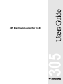
1
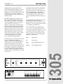
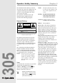
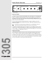
Users Guide
305
305 Distribution Amplifier (1x4)
Table of Contents
1
Chapter 2 Operator Safety Summary
2
Chapter 3 Fast Setup
3
Chapter 4 Front Panel Overview
4
Chapter 5 Rear Panel Overview
5
Chapter 6 Connecting to Other Gear
7
Chapter 7 Signal Flow Chart
10
Chapter 8 Troubleshooting
11
Chapter 9 Specifications
12
Chapter 10 Warranty and Service
13
Chapter 11 Declaration of Conformity
15
305
Chapter 1 Introduction
Rev A, 15 June, 1998
Symetrix part number 53305-0A00
Subject to change at our whim and fancy without
notice.
©1998, Symetrix, Inc. All right reserved.
Symetrix is a registered trademark of Symetrix, Inc.
Mention of third-party products is for informational
purposes only and constitutes neither an endorsement
nor a recommendation. Symetrix assumes no
responsibility with regard to the performance or use
of these products.
Under copyright laws, no part of this manual may be
reproduced or transmitted in any form or by any
means, electronic or mechanical, including photocopying, scanning, recording or by any information
storage and retrieval system, without permission, in
writing, from Symetrix, Inc.
i
6408 216th St. SW
Mountlake Terrace, WA 98043 USA
Tel (425) 778-7728
Fax (425) 778-7727
Email: [email protected]
Chapter 1
Introduction
Distribution amplifiers are generally used to
split one signal into multiple isolated sends.
For example, a sound reinforcement engineer
may wish to supply the mixer s mono output
signal to the house sound system, to a
backstage cueing system, to a DAT recorder
and to a media feed. The Symetrix 305 fits the
bill nicely, supplying four separate, isolated
outputs. In the event that one of the outputs
shorts (for example, the TV camera operator
inadvertently plugs a shorted cord into the
media feed), the other three outputs continue
to supply signal, unaffected by the short
circuit. The outputs are also isolated to
protect against ground hum problems.
The 305's input level control allows the sound
engineer to adjust the 305's input level
properly for the amount of signal being fed to
it from the mixer s output. The individual
output level trimpots allow each of the four
output levels to be tailored to their application.
For example, an output that is being fed to the
input of a DAT recorder may be adjusted to
provide a signal level that optimizes recording
resolution without overloading the input of the
DAT recorder.
The Symetrix 305 also offers a four-LED input
level meter, to assist the user in setting
optimum operating levels. The balanced input
stage is designed for high common mode
rejection and RF immunity. Output line drivers
are stable, short-circuit protected, and designed around industry standard 5532-type op
amps.
The Symetrix 305 offers high-quality, low-noise
audio distribution with convenient and
desirable features, all at a modest price. Only
minimal space in your equipment rack is needed
to contain this powerhouse unit.
We recommend that you read this manual
cover-to-cover. You will find the answers to
most of your questions inside. However, if you
are in a hurry, go directly to Chapter 3 (Fast
Setup). It will get you started quickly. Please
feel free to contact us if you have questions,
comments or suggestions.
Phone:
(425)778-7728
Fax:
(425)778-7727
Email:
[email protected]
Website:
www.symetrixaudio.com
INPUT
305
Congratulations on your purchase of the
Symetrix 305 Distribution Amplifier (1x4). The
305 accepts one balanced input signal and
distributes it to four independent outputs. The
volume of the input may be controlled via a
front panel trimpot, as can the volume of each
individual output.
OUTPUTS
A
B
C
D
CLIP
305
+10
DISTRIBUTION
AMPLIFIER (1x4)
0
-10
PWR
Front panel
OUTPUT
D
POWER
INPUT
C
INPUT
B
A
CONNECT TO
SYMETRIX PS-3
OR PS-3E POWER
SUPPLY ONLY.
MANUFACTURED BY SYMETRIX INC. LYNNWOOD, WA USA
THIS PRODUCT CONTAINS NO USER SERVICABLE PARTS.
FABRIQUÉ AUX E.-U. PAR SYMETRIX INC., LYNNWOOD, WASHINGTON.
RÉFÉREZ TOUTE RÉPARATION À UN TECHNICIEN QUALIFIÉ.
Rear panel
1
Operator Safety Summary
The information in this summary is intended
for persons who operate the equipment as well
as repair personnel. Specific warnings and
cautions are found throughout this manual
wherever they may apply.
The notational conventions used in this
manual and on the equipment itself are
described in the following paragraphs.
Equipment Markings
CAUTION
RISK OF ELECTRIC SHOCK
DO NOT OPEN
TO REDUCE THE RISK OF FIRE OR
SHOCK DO NOT EXPOSE
WARNING: ELECTRIC
THIS EQUIPMENT TO RAIN OR MOISTURE
DE CHOC ELECTRIQUE
AVIS: RISQUE
NE PAS OUVRIR
SEE OWNERS MANUAL. VOIR CAHIER D’INSTRUCTIONS.
No user serviceable parts inside. Refer servicing to qualified service personnel.
Il ne se trouve a l’interieur aucune piece pourvant entre reparée l’usager.
S’adresser a un reparateur compétent.
The lightning flash with arrowhead symbol
within an equilateral triangle is intended to
alert the user of the presence of uninsulated
dangerous voltage within the product’s
enclosure that may be of sufficient magnitude
to constitute a risk of electric shock to persons.
305
The exclamation point within an equilateral
triangle is intended to alert the user of the
presence of important operating and maintenance (servicing) instructions in the literature
accompanying the 305 (i.e. this manual).
Caution To prevent electric shock, do not
use the polarized plug supplied
with the 305 with any extension
cord, receptacle, or other outlet
unless the blades can be fully
inserted.
Terms
Several notational conventions are used in this
manual. Some paragraphs may use Note,
Caution, or Warning as a heading. Certain
typefaces and capitalization are used to
identify certain words. These are:
Note
2
Identifies information that needs
extra emphasis. A Note generally
supplies extra information to help
you to better use the 305.
Chapter 2
Caution
Identifies information that, if not
heeded, may cause damage to the
305 or other equipment in your
system.
Warning
Identifies information that, if
ignored, may be hazardous to
your health or that of others.
CAPITALS Controls, switches or other
markings on the 305's chassis.
Boldface
Strong emphasis.
Power source - This product is intended to
operate from a power source that does not
apply more than 255Vrms between the power
supply conductors or between either power
supply conductor and ground. A protective
ground connection, by way of the grounding
conductor in the power cord, is essential for
safe operation.
Danger from loss of ground - If the protective
ground connection is lost, all accessible
conductive parts, including knobs and
controls that may appear to be insulated, can
render an electric shock.
In-line power supply - This product receives its
operating power from the Symetrix PS-3 or PS-3E
power supply. This is the only power supply
approved for use with the product. Do not
connect the product to any other in-line, or
plug-in, transformer. The use of other power
sources may cause damage to the equipment
or present a shock hazard to the operator.
Operating location - Do not operate this
equipment under any of the following conditions: explosive atmospheres, in wet locations,
in inclement weather, improper or unknown AC
mains voltage, or if improperly fused.
Stay out of the box - To avoid personal injury
or injury to others, do not remove the product
covers or panels. Do not operate the product
without the covers and panels properly
installed.
Fast Setup
Chapter 3
Fast First-Time Setup
Follow these instructions to get your 305 up-and-running as quickly as possible. The intent of this
section is fast setup. Refer to later chapters for explanation of the 305's controls and functions.
1. Connect audio inputs and outputs. If you do not know how to do this, forget Fast Set-Up
and read Chapter 5.
2. Set INPUT level trim control straight up (12 o clock position).
3. Set OUTPUT level trim controls at maximum level (clockwise rotation).
4. Plug the 305 into an AC outlet using the external power supply.
Caution:
Failure to connect the 305 to the proper AC mains voltage may
cause fire and/or internal damage.
Warning:
Lethal voltages are present inside the chassis. There are no user
serviceable parts inside the chassis. Refer all service to qualified
service personnel or to the factory.
5. Apply line level audio signal to the input. Line level means previously amplified
audio, i.e. not the output of a microphone or other unamplified audio transducer.
6. Turn up the INPUT level pot until the red CLIP LED just barely lights. Then back the
level down just a bit until the CLIP LED doesn t come on any more, or only occasionally
flashes.
305
7. Now read the rest of this users guide.
3
Front Panel Overview
Chapter 4
INPUT
OUTPUTS
A
B
C
D
CLIP
305
DISTRIBUTION
AMPLIFIER (1x4)
+10
0
-10
PWR
Front panel drawing
Input Level Controls
The input level control on the 305 is marked INPUT. This control adjusts it's corresponding input
signal over a 30dB range. With signal applied to input, turn up the INPUT level pot until the red
CLIP LED just barely lights. Then back the level down just a bit until the CLIP LED doesn t come
on any more, or only occasionally flashes. This is the optimum setting and will provide the greatest
signal-to-noise ratio without distortion.
If your incoming signal position is unpredictable then we suggest a straight up (12 o'clock)
setting. Since the 305's input has 18dB of headroom above +4dBu, this setting should work well
under most conditions.
Note
If you wish to even out the variances in signal level, we recommend processing your
signal with the Symetrix 421m Automatic Leveler before it reaches the 305.
If you find that your input signal is very low (the output of a -10 consumer level device, such as
a CD player, for example), turn the INPUT level control clockwise to boost the signal. Conversely,
if you’re feeding a +8 broadcast level signal to the 305 then turn the INPUT level control counterclockwise until the proper LED display is achieved.
Output Level Controls
305
The four output level controls on the 305 are in the section marked OUTPUT and are labeled
A , B , C , and D . Use these controls to attenuate the output level over a 20dB range. Start
by turning all controls fully clockwise (unity gain). This will create equal levels from all outputs. If
for some reason you wish to reduce the level of certain outputs then turn the appropriate control(s)
counterclockwise. Otherwise, for better overall system performance, it s best to leave the controls
wide open (full clockwise) for the hottest possible output signals.
4
Chapter 5
Rear Panel Overview
OUTPUT
D
POWER
INPUT
C
INPUT
B
A
CONNECT TO
SYMETRIX PS-3
OR PS-3E POWER
SUPPLY ONLY.
MANUFACTURED BY SYMETRIX INC. LYNNWOOD, WA USA
THIS PRODUCT CONTAINS NO USER SERVICABLE PARTS.
FABRIQUÉ AUX E.-U. PAR SYMETRIX INC., LYNNWOOD, WASHINGTON.
RÉFÉREZ TOUTE RÉPARATION À UN TECHNICIEN QUALIFIÉ.
Rear panel drawing
The 305 is fitted with removable terminal blocks for both input and output connections. While not
absolutely necessary, it is usually much easier to unplug the removable block before making or
changing connections.
INPUT
The 305 s input is balanced. Of course, it may be used in unbalanced configurations, but for
optimum system wide performance (best noise rejection) balanced operation is highly recommended whenever possible. Be sure to use shielded cable for both input and output connections.
The wire should always be two-conductor plus shield, even for unbalanced connections.
For a balanced input signal:
1.
Connect the incoming signal + (high) to the + INPUT terminal of the 305.
2.
Connect the incoming signal - (low) to the - INPUT terminal of the 305.
3.
Connect the incoming signal ground (shield) to the ground terminal of the 305. Repeat
for all inputs.
1.
Connect the incoming signal + (high) to the + INPUT terminal of the 305. Use
the red wire.
2.
Connect the incoming signal ground to the - INPUT terminal of the 305. Use the
black wire.
3.
Connect the cable shield at the ground connection of the 305 only.
If you experience hum or noise, make sure that both the 305 and the device which you are feeding
to the 305 s input are grounded on the same AC mains circuit. If this is not the source of the noise
problem, you must isolate the unbalanced output from the balanced input with an audio transformer or matchbox.
If the unbalanced output of the device preceding the 305 is -10dBV (semi-pro or consumer level),
the Symetrix 303 Interface Amplifier is an excellent choice for isolation. Not only will the 303
convert the unbalanced signal to an isolated balanced signal, it will also boost the -10dBV signal to
the +4dBu level at which the 305 was designed to operate.
OUTPUTS
The 305's output is an active balanced circuit and should be used to feed balanced audio inputs.
Use two-conductor shielded audio cable for all connections.
Feeding balanced inputs:
1.
Connect the + (high) OUTPUT terminal of the 305 to the + (high) of the input
of the device which you are feeding.
2.
Connect the - (low) OUTPUT terminal of the 305 to the - (low) of the input of
the device which you are feeding.
3.
Connect cable shield to the ground of the 305 and the ground connection of the
device which you are feeding.
5
305
For an unbalanced input signal, using two-conductor shielded cables:
Feeding unbalanced inputs:
WE DON’T RECOMMEND IT. If you must feed an unbalanced input with the 305, you should
isolate the two devices with either an audio transformer or an interface matching device (a matchbox ). The 305 follows the AES standards for balanced audio circuits. The ground connections of
the amplifier are chassis ground.
If you must connect the output of the 305 directly to an unbalanced input, try this procedure. Use
two-conductor shielded audio cable.
1.
Connect the + (high) OUTPUT terminal of the 305 to the + (high) of the
unbalanced input.
2.
Make no connection to the - (low) OUTPUT terminal of the 305.
3.
Connect the cable shield at the 305 s ground and at the input connector of the
unbalanced input.
The output signal level of the 305 will be 6 dB lower when driving an unbalanced input without a
transformer or matching interface device.
305
If you experience hum or noise, make sure that both the 305 and the device which you are feeding
are grounded on the same AC mains circuit. If this is not the source of the noise problem, you must
isolate the balanced output from the unbalanced input with an audio transformer or matchbox.
6
Chapter 6
Connecting to Other Gear
Matching Levels vs Matching Impedances
In any audio equipment application, the question of matching inevitably comes up. Without
digging a hole any deeper than absolutely necessary, we offer the following discussion to (hopefully) clarify your understanding of the subject.
Over the years, we have all had impedance matching pounded into our heads. This is important
only for vintage audio systems, power amplifiers, and RF. Technically speaking, the reason is
power transfer, which reaches a maximum when source and load are matched. Modern audio
systems are voltage transmission systems and source and load matching is not only unnecessary,
but undesirable as well.
Vintage audio systems operate at 600 ohms (or some other impedance value), and must be
matched, both at their inputs and at their outputs. Generally speaking, if you are dealing
with equipment that uses vacuum tubes, or was designed prior to 1970, you should be
concerned about matching. These units were designed when audio systems were based on
maximum power transfer, hence the need for input/output matching.
Power amplifiers are fussy because an abnormally low load impedance generally means a
visit to the amp hospital. Thus, it s important to know what the total impedance of the pile
of speakers connected to the amplifier really is.
RF systems are matched because we really are concerned with maximum power transfer
and with matching the impedance of the transmission line (keeps nasty things from
happening). Video signals (composite, baseband, or otherwise) should be treated like RF.
Some folks seem to believe that balanced/unbalanced lines and impedances are related; or even
worse that they are associated with a particular type of connector. Not so. Unbalanced signals are
not necessarily high-impedance and balanced signals/lines are not necessarily low-impedance.
Similarly, although 1/4 inch jacks are typically used for things like guitars (which are high-impedance and unbalanced), this does not predispose them to this use alone. After all, 1/4 inch jacks are
sometimes used for loudspeakers, which are anything but high-impedance. Therefore, the presence
of 3-pin XLR connectors should not be construed to mean that the input or output is low-impedance (or high-impedance). The same applies to 1/4 inch jacks.
Signal level is very important. Mismatch causes either loss of headroom or loss of signal-to-noise ratio.
Thus, microphone inputs should only see signals originating from a microphone, a direct (DI) box, or an
output designated microphone-level output. Electrically, this is in the range of approximately -70 to -20
dBm. Line inputs should only see signals in the -10 to +24 dBm/dBu range. Guitars, high-impedance
microphones, and many electronic keyboards do not qualify as line-level sources.
The impedance relation between outputs and inputs needs to be considered, but only in the
following way - Always make sure that a device s input impedance is higher than the output
source impedance of the device that drives it.
Some manufacturers state a relatively high-impedance figure as the output impedance of their
equipment. What they really mean is that this is the minimum load impedance that they would like
their gear to see. In most cases, seeing a output impedance figure of 10,000 (10K) ohms or higher
from modern equipment that requires power (batteries or AC) is an instance of this type of rating. If
so, then the input impedance of the succeeding input must be equal to or greater than the output
impedance of the driving device.
Symetrix equipment inputs are designed to bridge the output of whatever device drives the input
(i.e. to be greater than 10 times the actual source impedance). Symetrix equipment outputs are
designed to drive 600-ohm or higher loads (600-ohm loads are an archaic practice that won t go
away). You don t need to terminate the output with a 600-ohm resistor if you aren t driving a 600ohm load. (If you don t understand the concept of termination, you probably don t need to
anyway.)
7
305
So, what is really important? Signal level, and (to a much lesser degree), the impedance relation
between an output (signal source) and the input that it connects to (signal receiver).
The two facts that you need to derive from this discussion are:
Match signal levels for best headroom and signal-to-noise ratio.
For audio, impedance matching is only needed for vintage equipment and power amplifier
outputs. In all other cases, ensure that your inputs bridge your outputs (meaning the
inputs are in the range of 2 to 200 times the output source impedance).
Signal Levels
The 305 is designed around studio/professional line levels: +4 dBu or 1.23 volts RMS. The unit is
quiet enough to operate at lower signal levels such as those found in semi-pro or musical instrument (MI) equipment (-10 dBv or 300 millivolts).
I/O Impedances
The 305 is designed to interface into almost any recording studio or sound reinforcement application. This includes:
600-ohm systems where input and output impedances are matched.
Modern bridging systems where inputs bridge and outputs are low source impedances
(voltage transmission systems).
The 305's input impedance is 20-kilohms balanced. The inputs may be driven from any balanced
source capable of delivering at least -10 dBv into the aforementioned impedances.
The 305's output impedance is 200 ohms balanced, 100 ohms unbalanced. The output line driver
delivers +22 dBu into 600-ohm balanced loads or +18 dBm into 600-ohm unbalanced loads.
Input and Output Connections
The illustration on the next page shows how to connect the 305 to balanced and unbalanced
sources and loads. Please remember that unbalanced operation is not recommended.
305
If you must operate the 305 from unbalanced sources, run a 2-conductor shielded cable (that s two
conductors plus the shield) from the source to the 305. At the source, connect the cable
connector s sleeve to one conductor (this will be the - or the low conductor) and connect the
tip to the remaining + or high conductor, leaving the shield unconnected. Connect the shield
to the chassis connection and the cable s - and + to the corresponding 305 input connection.
This is the preferred method as it makes best use of the 305's balanced input (even though the
source is unbalanced). An alternative shown in the illustration converts the 305's balanced input
into an unbalanced input at the input connector. This works, but is more susceptible to hum and
buzz than the preferred method. There is no level difference between methods.
You can drive unbalanced loads with the 305's outputs by using the XLR connector with pin 3 left
open. In an emergency (the show must go on), you can ground pin 3, but if you have the
choice...leave it open. If you must ground pin 3, it must be grounded at the 305, rather than at the
other end of the cable. The price, regardless of whether or not pin 3 is grounded is 6 dB less output
level. If your system is wired with pin 3 hot, and you are driving an unbalanced load, pin 2 must
float.
8
Balanced Terminal Strip
(When Using CIRCUIT Ground)
(Wire Shield Not Connected)
Channel
Input
Two Conductor
Shielded Cable
Balanced Female XLR
(When Using CIRCUIT Ground)
Channel
Input
Two Conductor
Shielded Cable
TRS Plug
Channel
Input
(When Using CIRCUIT Ground)
Tip = High
Ring = Low
Sleeve = Not Connected
(Wire Shield Not Connected)
TIP
RING
SLEEVE
Two Conductor
Shielded Cable
TS Plug
Channel
Input
(When Using CIRCUIT Ground)
Tip = High
Sleeve = Low
(Wire Shield Not Connected)
TIP
SLEEVE
Two Conductor
Shielded Cable
RCA Plug
Channel
Input
(When Using CIRCUIT Ground)
Tip = High
Sleeve = Low
(Wire Shield Not Connected)
305
1 3 2
Pin 1=Not Connected
Pin 2 = High
Pin 3 = Low
Shield Tab = Not Connected
Two Conductor
Shielded Cable
Balanced Male XLR
Channel
Output
(When Using CIRCUIT Ground)
Pin 1= Circuit Ground
Pin 2 = High
Pin 3 = Low
Shield Tab = Not Connected
2 3 1
Two Conductor
Shielded Cable
TS Plug
Channel
Output
(When Using CIRCUIT Ground)
Tip = High
Sleeve = Shield
(Wire Low Not Connected)
TIP
SLEEVE
Two Conductor
Shielded Cable
9
Signal Flow Chart
Input
Level
Chapter 7
Output A
Level
OUT
A
Output B
Level
OUT
B
CLIP
Input LED
Display
+10
0
Output C
Level
OUT
C
-10
Output D
Level
305
OUT
D
10
Chapter 8
Troubleshooting
Troubleshooting Chart
PROBABLE CAUSE
No output signal
Check cables and connections. Is the input driven by an output, and
output driving input? Verify cables, source and load by patching
input and output connections together, at the unit. Check for AC power
presence.
Hum or buzz in output
Check input and output connector wiring (refer to page 9). Ground
loop: check related system equipment grounding. Are all system
components on the same AC ground?
Distortion
Check the level of the input signal on the 305's LED display. Is the
CLIP light on all the time? If so, reduce the incoming signal level by
turning the INPUT level counterclockwise. Is the incoming signal
already distorted? Listen up stream from the 305 to make sure
you re feeding it a clean signal.
Noise (hiss)
Check input signal level and input level control settings. The input
signal may be too low. If so, boost the incoming signal (if possible). Is
the input signal already noisy? Listen up stream from the 305 to
determine that you are feeding it a clean signal. Verify that all system
components on the same AC ground.
No LED display
Is the unit plugged in, and turned on? Is the AC outlet OK? Is a signal
of at least -10dB being fed to the input of the 305?
305
SYMPTOM
11
Specifications
Chapter 9
Architects and Engineers Specifications
The Symetrix 305 Distribution Amplifier shall
be a one channel audio distribution amplifier
consisting of one electronically balanced
input amplifier and four electronically
balanced output amplifiers. There shall be a
master gain adjustment circuit capable of up
to 15dB of gain or 15dB of loss for the
purpose of optimally matching incoming
signal level(s). There shall be a four-LED
array for the indication of the signal level
applied to the output drive circuits. The
LED s shall be labelled CLIP, +10, 0, and -10
corresponding to internal signal levels of
+18dBu, +10dBu, 0dBu, and -10dBu.
The output shall be capable of driving a 600ohm balanced load to a level of +22 dBu.
The maximum output level into a balanced
bridging load (20K Ohms) shall be +26 dBu.
The output will offer an individual attenuator
with a range of 0 to -20 dB.
width of 30 kHz. Residual noise will be >100
dB below a +4 dBu input signal when
measured with an A-weighting filter.
The unit shall occupy half of the width of one
rack space. The physical dimensions shall be
1.75"H x 8.5"W x 6.5"D; 4.445cm H x 21.59cm
W x 15.875cm D.
The distribution amplifier shall operate by
means of a Symetrix PS-3 or PS-3E power
supply connected to 117V AC nominal,
(95-130V AC), 50-60 Hz or 230V AC nominal,
(165-255V AC), 50 Hz.
The distribution amplifier shall be a Symetrix,
Inc. model 305 Distribution Amplifier (1x4).
305
Frequency response through the amplifier
shall be ±1/2 dB, measured between 20 Hz and
20 kHz. THD+Noise shall be less than
0.009% measured at +26dBu with a band-
Specifications
Input/Output
Maximum Input Level
Maximum Output Level
Input Impedance
Output Impedance
Performance Data
Frequency Response
THD+Noise
±1/2 dB, 20 Hz to 20 kHz
Signal to Noise Ratio
Dynamic Range
Common Mode Rejection
Input Gain Range
Output Gain Range
Physical
Size (hwd)
Shipping Weight
Electrical
Power Requirements
12
+26 dBu Balanced
+26 dBu Balanced (20k Ohm load)
+22 dBu (600 Ohm load)
20k Ohms Balanced, 10k Ohms Unbalanced
200 Ohms Balanced, 100 Ohms Unbalanced
<.009% at +26dBu,
30kHz measurement bandwidth
>100dB, A-weighted, ref. to +4dBu
>125 dB, A-weighted
>40 dB, 20 Hz to 20 kHz
±15dB
0 to -20dB
1.75 x 8.5 x 6.5 in., 4.445 x 21.59 x 15.875 cm.
4.5 lbs
117V AC nominal, 95-130V AC, 50 to 60 Hz
230V AC nominal, 165-255V AC, 50Hz
In the interest of continuous product improvement, Symetrix, Inc.
reserves the right to alter, change, or modify these specifications
without prior notice.
©1998, Symetrix, Inc. All rights reserved.
Chapter 10
Warranty and Service
305 Limited Warranty
The foregoing warranties are in lieu of all
other warranties, whether oral, written,
express, implied or statutory. Symetrix, Inc.
expressly disclaims any IMPLIED warranties, including fitness for a particular
purpose or merchantability. Symetrix's
warranty obligation and buyer s remedies
hereunder are SOLELY and exclusively as
stated herein.
This Symetrix product is designed and
manufactured for use in professional and
studio audio systems and is not intended for
other usage. With respect to products
purchased by consumers for personal, family,
or household use, Symetrix expressly
disclaims all implied warranties, including
but not limited to warranties of merchantability and fitness for a particular purpose.
This limited warranty, with all terms, conditions and disclaimers set forth herein, shall
extend to the original purchaser and anyone
who purchases the product within the
specified warranty period.
Symetrix does not authorize any third party,
including any dealer or sales representative,
to assume any liability or make any additional warranties or representation regarding
this product information on behalf of
Symetrix.
This limited warranty gives the buyer certain
rights. You may have additional rights
provided by applicable law.
Limitation of Liability
The total liability of Symetrix on any claim,
whether in contract, tort (including negligence) or otherwise arising out of, connected with, or resulting from the manufacture, sale, delivery, resale, repair, replacement or use of any product will not exceed
the price allocable to the product or any part
thereof which gives rise to the claim. In no
event will Symetrix be liable for any inciden-
tal or consequential damages including but
not limited to damage for loss of revenue,
cost of capital, claims of customers for
service interruptions or failure to supply, and
costs and expenses incurred in connection
with labor, overhead, transportation, installation or removal of products or substitute
facilities or supply houses.
13
305
Symetrix, Inc. expressly warrants that the product
will be free from defects in material and
workmanship for (18) months. Symetrix's
obligations under this warranty will be
limited to repairing or replacing, at
Symetrix's option, the part or parts of the
product which prove defective in material or
workmanship within (18) months from date
of shipment, provided that the Buyer gives
Symetrix prompt notice of any defect or
failure and satisfactory proof thereof.
Products may be returned by Buyer only
after a Return Authorization number (RA)
has been obtained from Symetrix. Buyer will
prepay all freight charges to return the
product to the Symetrix factory. Symetrix
reserves the right to inspect any products
which may be the subject of any warranty
claim before repair or replacement is carried
out. Symetrix may, at its option, require
proof of the original date of purchase (dated
copy of original retail dealer's invoice). Final
determination of warranty coverage lies
solely with Symetrix. Products repaired
under warranty will be returned freight
prepaid by Symetrix via United Parcel
Service (surface), to any location within the
Continental United States. At Buyer's
request the shipment may be returned via
airfreight at Buyer's expense. Outside the
Continental United States, products will be
returned freight collect.
Servicing the 305
If you have determined that your 305 requires repair services and you live outside of the
United States, please contact your local Symetrix dealer or distributor for instructions on
how to obtain service. If you reside in the U.S. then proceed as follows:
Before sending anything to Symetrix, contact our Customer Service Department for a
return authorization (RA) number. The telephone number is (425) 778-7728 or email:
[email protected]
In-warranty Repairs
To get your 305 repaired under the terms of the warranty:
1.
Call us for an RA number.
2.
Pack the unit in its original packaging materials.
3.
Include your name, address, daytime telephone number, and a brief
statement of the problem.
4.
Write the RA number on the outside of the box.
5.
Ship the unit to Symetrix, freight prepaid.
We do not accept freight collect shipments.
Repairs made in-warranty will cost you only one-way freight charges. We'll prepay the
return (surface) freight.
305
If you send us your product in substandard packaging, we will charge you for factory
shipping materials. If you don t have the factory packaging materials, please use an
oversized carton, wrap the unit in a plastic bag, and surround it with bubble-wrap. Pack the
box full of Styrofoam peanuts. Be sure there is enough clearance in the carton to protect
the rack ears (you wouldn't believe how many units are returned with bent ears). We will
return the unit in Symetrix packaging. Of course, if the repair is due to operator error, parts
and labor will be charged. In any event, if there are charges for the repair costs, you will
pay for the return freight. All charges will be COD unless you have made other arrangements (prepaid, Visa or Mastercard).
Out-of-warranty Repairs
If the warranty period has passed, you'll be billed for all necessary parts, labor, packaging
materials, and freight charges. Please remember, you must call for an RA number before
sending the unit to Symetrix.
14
Chapter 11
Declaration of Conformity
Declaration of Conformity
We, Symetrix Incorporated,
6408 216th St. SW, Mountlake Terrace, Washington, USA,
declare under our sole responsibility that the product:
305 Distribution Amplifier (1x4)
to which this declaration relates,
is in conformity with the following standards:
EN 60065
Safety requirements for mains operated electronic and related
apparatus for household and similar general use.
EN 50081-1
Electromagnetic compatibility - Generic emission standard
Part 1: Residential, commercial, and light industry.
EN 50082-1
Electromagnetic compatibility - Generic immunity standard
Part 1: Residential, commercial, and light industry.
The technical construction file is maintained at:
Symetrix, Inc.
6408 216th St. SW
Mountlake Terrace, WA, 98043
USA
305
The authorized representative located within the European Community is:
World Marketing Associates
P.O. Box 100
St. Austell, Cornwall, PL26 6YU, U.K.
Date of issue: June 15, 1998
Place of issue:Mountlake Terrace, Washington, USA
Authorized signature:
Dane Butcher, President, Symetrix Incorporated.
15
305
305
305
20
Symetrix, Inc.
6408 216th St. SW
Mountlake Terrace, WA, 98043
USA
Tel: (425) 778-7728
Fax: (425) 778-7727
Website: http://www.symetrixaudio.com
Email: [email protected]