1
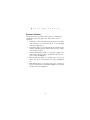
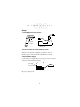
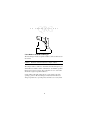
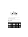
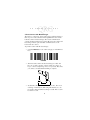
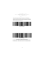
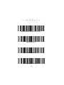
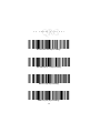
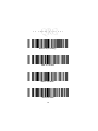
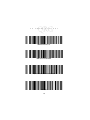
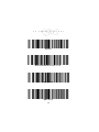
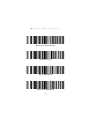
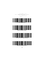
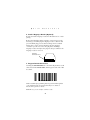
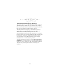
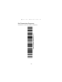
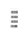
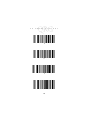
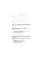
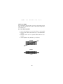
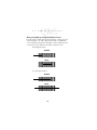
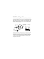
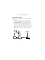
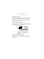
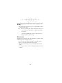
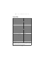
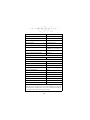
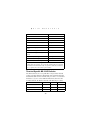
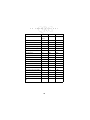
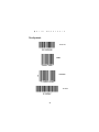
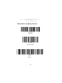
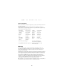
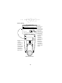
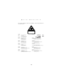
L S 3 0 7 0 S c a n n e r L S 3 0 7 0 S c a n n e r 1997-1999 SYMBOL TECHNOLOGIES, INC. All rights reserved. Symbol reserves the right to make changes to any product to improve reliability, function, or design. Symbol does not assume any product liability arising out of, or in connection with, the application or use of any product, circuit, or application described herein. No license is granted, either expressly or by implication, estoppel, or otherwise under any patent right or patent, covering or relating to any combination, system, apparatus, machine, material, method, or process in which Symbol products might be used. An implied license only exists for equipment, circuits, and subsystems contained in Symbol products. Symbol is a registered trademark of Symbol Technologies, Inc. Other product names mentioned in this manual may be trademarks or registered trademarks of their respective companies and are hereby acknowledged. Symbol Technologies, Inc. One Symbol Plaza Holtsville, N.Y. 11742-1300 http://www.symbol.com Patents This product is covered by one or more of the following U.S. and foreign Patents: U.S. Patent No.4,360,798; 4,369,361; 4,387,297; 4,460,120; 4,496,831; 4,593,186; 4,603,262; 4,607,156; 4,652,750; 4,673,805; 4,736,095; 4,758,717; 4,816,660; 4,845,350; 4,896,026; 4,897,532; 4,923,281; 4,933,538; 4,992,717; 5,015,833; 5,017,765; 5,021,641; 5,029,183; 5,047,617; 5,103,461; 5,113,445; 5,130,520; 5,140,144; 5,142,550; 5,149,950; 5,157,687; 5,168,148; 5,168,149; 5,180,904; 5,229,591; 5,230,088; 5,235,167; 5,243,655; 5,247,162; 5,250,791; 5,250,792; 5,262,627; 5,262,628; 5,266,787; 5,278,398; 5,280,162; 5,280,163; 5,280,164; 5,280,498; 5,304,786; 5,304,788; 5,306,900; 5,321,246; 5,324,924; 5,337,361; 5,367,151; 5,373,148; 5,378,882; 5,396,053; 5,396,055; 5,399,846; 5,408,081; 5,410,139; 5,410,140; 5,412,198; 5,418,812; 5,420,411; 5,436,440; 5,444,231; 5,449,891; 5,449,893; 5,468,949; 5,471,042; 5,478,998; 5,479,000; 5,479,002; 5,479,441; 5,504,322; 5,519,577; 5,528,621; 5,532,469; 5,543,610; 5,545,889; 5,552,592; 5,578,810; 5,581,070; 5,589,679; 5,589,680; 5,608,202; 5,612,531; 5,619,028; 5,664,229; 5,668,803; 5,675,139; 5,693,929; 5,698,835; 5,705,800; 5,714,746; 5,723,851; 5,734,152; 5,734,153; 5,745,794; 5,754,587; 5,762,516; 5,763,863; 5,767,500; 5,789,728; 5,808,287; 5,811,785; 5,811,787; 5,815,811; 5,821,519; 5,821,520; 5,823,812; 5,828,050; 5,850,078; 5,861,615; 5,874,720; 5,875,415; 5,900,617; 5,902,989; 5,907,146; 5,912,450; 5,914,478; 5,917,173; 5,920,059; 5,923,025;D305,885; D341,584; D344,501; D359,483; D362,453; D363,700; D363,918; D370,478; D383,124; D391,250; D405,077; D406,581. Invention No. 55,358; 62,539; 69,060; 69,187 (Taiwan); No. 1,601,796; 1,907,875; 1,955,269 (Japan). European Patent 367,299; 414,281; 367,300; 367,298; UK 2,072,832; France 81/ 03938; Italy 1,138,713. rev. 7/99 Q u i c k R e f e r e n c e Scanner Varieties The LS 3070 scanners include a wide variety of scanning types, optimized for particular applications. The varieties are the following: • • • • • Standard - for most Class II scanning applications, in which symbol density (5 to 55 mil) and range (0 - 35 in.) fall within relatively normal ranges. Long Range (LR) - for Class II applications with short range reading on medium density symbols and long range reading on low density symbols. Advanced Long Range (ALR) - for long range reading on medium and low-density symbols, optimized by the increased power of the Class IIIA laser. Extra Long Range (XLR) - for scanning ranges of up to 180 inches (457 cm) on 55 mil symbols, also using a Class IIIA laser. High Visibility (HV) - for scanning ranges up to 33 inches (86 cm) on 55 mil symbols, and ambient sunlight up to 10,000 ft. candles, using a Class IIIA laser. 1 L S 3 0 7 0 S c a n n e r Setup 1. Identify System Components Power Supply LS 3070 Scanner RL 470 Base/Interface/ Charger Unit 2. Connect Cable to the Base/Charger Unit This procedure depends on which host terminal is used. For complete details per terminal type, refer to the RL 470 Base Station Interface portion of the LS 3070 Product Reference Guide. 3. Attach Power Supply Connect the power supply to the power input port on the rear panel of the LS 3070 base/interface/charger. Power Supply Connection Port Host Connect the power supply to a receptacle supplying AC power of the proper voltage level. 2 Q u i c k R e f e r e n c e 4. Insert Scanner Into Base/Charger and Charge the Battery Before its first use, the LS 3070 battery must be charged. After the power supply has been connected, insert the scanner into the base/charger cradle as follows. a. Place the nose of the scanner into the large rectangular receptacle of the base/charger. b. Then place the handle of the scanner into the opening of the smaller latched receptacle. c. Press down firmly until the bottom of the handle seats snugly into the receptacle and engages the latch. Caution: Use of excessive force in placing the scanner into the base can damage the charging contacts on the scanner or base. Such damage can interfere with or prevent charging of the scanner’s batteries by the base. Check the charge-status indicator LED; it stays steadily on while the battery is charging and blinks rapidly when the battery is fully charged. Full charge takes less than two hours. To remove the scanner from the base/charger, grasp the handle of the scanner and lift the bottom of the handle out of the latched receptacle, thereby freeing the scanner from the base. Caution: Trying to remove the scanner nose first, instead of handle first, can break the latch in the base receptacle. 3 L S 3 0 7 0 S c a n n e r 5. Set Address of the Base/Charger The base/charger must be assigned an address, with a value between 01 and 7E. Caution: Each base station must have a unique address. The unique address of the base determines the initial frequency on which the base and the scanner communicate. To minimize possible interference between systems, bases which are close to each other should be assigned sequential addresses. Set the address through setting the two rotary dials, located by opening a panel on the base/charger’s underside. Turn the base/ charger upside down, open the panel, and notice two rotary dials. 4 Q u i c k R e f e r e n c e Insert Screwdriver in Slot 0 0 High Order 10 Position Low Order 16 Position Rotary Switches The first is a 10-position (0 to 9, high order address digit) and the second a 16-position (0 to F, low order address digit). Digits are printed sequentially around each circle. Note that positions 8 and 9 are illegal on the 10-position switch. Set the desired address with a small screwdriver; possible addresses are listed on the next page. Note that too large a screwdriver can damage the switches. When the address is set, close the panel, turn the base/charger rightside up again. Possible Base/Charger Addresses 01 02 03 04 05 06 07 08 09 0A 0B 0C 0D 0E 0F 10 11 12 13 14 15 16 17 18 19 1A 1B 1C 1D 1E 1F 20 21 22 23 24 25 26 27 28 29 2A 2B 2C 2D 2E 2F 30 31 32 33 34 35 36 37 38 39 3A 3B 3C 3D 3E 3F 40 41 42 43 44 45 46 47 48 49 4A 4B 4C 4D 4E 4F 50 51 52 53 54 55 56 57 58 59 5A 5B 5C 5D 5E 5F 60 61 62 63 64 65 66 67 68 69 6A 6B 6C 6D 6E 6F 70 71 72 73 74 75 76 77 78 79 7A 7B 7C 7D 7E 5 L S 3 0 7 0 S c a n n e r 6. Pair Scanner with Base/Charger The wireless “connection” between the scanner and base/charger is the low power radio transmission through RF transceivers in the both the scanner and base/charger. The actual communication consists of bidirectional message packets. However, the scanner and base/charger must be paired for this communication to work between the two devices. To pair the scanner with the base/charger: • Scan the PAIRING bar code on the next page or on the RL 470 base. PAIRING Then insert the scanner into the base/charger’s cradle. You have 15 seconds to do this, or there will be error beeps (4 beeps = unsuccessful pairing or base not powered). Note that you cannot scan data until this linking is complete. • At that time, through the scanner’s contact shoe, there is an exchange of information (addressing, RF channels, etc.) between the scanner and the base/charger’s cradle. This occurs in less than a second. • 6 Q u i c k • R e f e r e n c e After that exchange, the scanner and base/charger are paired. Successful pairing is indicated by as warble beep; failure, or unsuccessful link, is indicated by a Lo Lo Lo Lo beep. 7. Set Host Type Each Interface Cable Assembly defaults to a given host. Below is a list of the assemblies and their corresponding default hosts. If you wish to change the type of host, find and scan the proper bar code on the following pages. Cable Assy. Default IK-0100, -0101 IK-1005, -1006 IK-0200 IK-0300 IK-0400 IK-0401 IK-0402, -0403 IK-0406, -0409 IK-0413 IK-0500 IK-0600 IK-0700 IK-0800 — 0803 IK-0900 IK-0901 IK-0902 IK-1001, -1002 IK-1003, -1004 IK-1100 IK-1200, -1201 IK-1300 IK-1301 IK-1400 IK-1500, -1501 IBM 4683/93 Port 5B; 4683/84 Port 17 ICL 9505, 9507, 9518; 9520 OCIA IBM 3683, 3684 Keybd Wedge IBM 3653 Kybd Wedge IBM PC/AT, Telex Memorex Kybd Wedges IBM PS/2 - 30, 50, 55SX, 60, 70, 80 NCR 7052 Wedge; Fujitsu 9000 Wedge IBM 3161/319X; IBM 3151, 347X Wedges Wyse 50 Wedge NCR 2152 Tel Kybd Wedge NCR 2151 Tel Kybd Wedge NCR 280 Kybd Wedge Standard RS-232C Fujitsu 9000 OCR Fujitsu 7770, 7880, 7990, 8770 OCR IBM 3653, 3683/3684 OCR NCR 2152, 2257, 2950; 215X, 7050 OCIA Nixdorf 8812 OCIA; NCR 2126-1120 OCIA IBM 4683/93 Port 9B IBM 3178; IBM 3278 Wedges Wyse 60, 85, 150, 160, 185 Wedges HP 7000/XX, 239X Wedges DEC VT 2XX/3XX/4XX Wedges Dual RS-232C 7 L S 3 0 7 0 S c a n n e r In some cases, two bar codes may correspond to one interface type; this happens when different software revisions exist for the same host type. If there are two bar codes for your host type, try the first bar code; if that does not work, then try the second one. Single Port RS-232 Dual Port RS-232 Four Options for Dual Port RS-232 Follow For IK-1500, Port 1 = Male, TxD on Pin 2; Port 2 = Female, TxD on Pin 3. For IK-1501, Port 1 = Male, TxD on Pin 3; Port 2 = Female, TxD on Pin 2. 8 Q u i c k R e f e r e n c e Dual Port RS-232: Transmit and Receive from Port 1 Dual Port RS-232: Transmit to Ports 1 and 2 — Receive from Port 1 Dual Port RS-232: Transmit and Receive from Port 2 Dual Port RS-232: Transmit to Ports 1 and 2 — Receive from Port 2 9 L S 3 0 7 0 S c a n n e r IBM PC/AT, IBM PS2-50/55SX/60/70/80 and Clones IBM PC/XT And Clones IBM PS2-30 and Clones IBM 3653 Keyboard Wedge 10 Q u i c k R e f e r e n c e IBM 3683/3684 Calc 35 Keyboard Wedge IBM 3683/3684 Calc 48 Keyboard Wedge IBM 3683/3684 Calc 116 Keyboard Wedge IBM 3683/3684 Tel 35 Keyboard Wedge 11 L S 3 0 7 0 S c a n n e r IBM 3683/3684 Tel 48 Keyboard Wedge IBM 3683/3684 Tel 116 Keyboard Wedge NCR 2151 (Tel) Keyboard Wedge NCR 2151 (Calc) Keyboard Wedge 12 Q u i c k R e f e r e n c e NCR 2152 (Tel) Keyboard Wedge NCR 2152 (Calc) Keyboard Wedge NCR 280 Keyboard Wedge NCR 255/2152/2154/2155, NCR 2126-1120 NCR 2157/2257/7050, NCR “S” 7052 OCIA 13 L S 3 0 7 0 S c a n n e r NCR 7052 Keyboard Wedge NCR “F” 7052 OCIA NCR “S” 2950 OCIA Nixdorf 8812 OCIA 14 Q u i c k R e f e r e n c e ICL 9505/9507/9518/9520 OCIA Spectra Physics OCIA IBM 4683/4684 Port 5B 4693 IBM 4683/4684 Port 9B 4693 15 L S 3 0 7 0 S c a n n e r IBM 4683/4684 Port 17 IBM 3653/3683/3684 OCR Fujitsu 7770/7880/7990/ 8770/9000 OCR HP 239X 16 Q u i c k R e f e r e n c e HP 700-9X DEC VT 2XX/3XX/4XX DEC 420 (Later Software Revision) IBM 3178 17 L S 3 0 7 0 S c a n n e r IBM 3278 IBM 319X/347X/348X Telex Memorex 122 IBM 3151/316X IBM 3179/3180 18 Q u i c k R e f e r e n c e IBM 3180 (Later Software Revision) Telex Memorex 88 Wyse 50 (ASCII Keybd) Wyse 60/30/160 (ASCII Keybd) 19 L S 3 0 7 0 S c a n n e r Wyse 60/160 (PC Keybd) Wyse 60/150 (ANSI 101 Keybd) Wyse 85/150+/185/160 (ANSI 105 Keybd) HP 2392 (Later Software Revision) 20 Q u i c k R e f e r e n c e 8. Install a Magstripe Reader (Optional) If desired, install a magstripe reader. Do this either before or after pairing. Remove the blank plug in the magstripe connection port on the base/charger, and then plug the magstripe reader’s cable into this port. The blank plug protects the base/charger from accidental damage due to static electrical discharge into the magstripe connection port. Do not remove the plug unless installing a magstripe reader, and replace the plug into the port whenever the magstripe reader is removed. Magstripe Connection Port 9. Program Default Parameters Scanning the SET DEFAULTS bar code returns all parameters to the values listed in the Default Table, which appears at the end of this document. SET DEFAULTS Other customized programming must be performed through bar codes available in the LS 3070 Product Reference Guide or Advanced Programmer’s Guide. With this set, you are ready to scan bar codes. 21 L S 3 0 7 0 S c a n n e r 10. Set Transmission Frequency (Optional) The scanner and base can communicate on a number of different channel frequencies, which varies by country. In most countries, there are 80 available channels (numbered 2 through 81); in France, there are only 9 channels (numbered 46 through 54). The initial transmission frequency is determined by the base’s unique address, so neighboring LS 3070 systems operate on different channels without interfering with each other. Occassionally, there may be noticeable interference on a channel from some other source of radio transmissions. The system has been programmed to change the channel automatically if it detects excessive interference, but the channel may also be changed manually if there are communications problems. To set the transmission frequency, scan the SELECT CHANNEL NUMBER bar code appropriate for your country. Then scan two numeric bar codes to set the two-digit channel number within the allowable range (46 through 54 in France, 02 through 81 elsewhere). 22 Q u i c k R e f e r e n c e Set Transmission Frequency SELECT CHANNEL NUMBER (02-81) Scan this bar code for all countries except France. 23 L S 3 0 7 0 S c a n n e r SELECT CHANNEL NUMBER (46-54) Scan this bar code for France only. 24 Q u i c k R e f e r e n c e 0 1 2 3 25 L S 3 0 7 0 S c a n n e r 4 5 6 7 26 Q u i c k R e f e r e n c e 8 9 CANCEL 27 L S 3 0 7 0 S c a n n e r Scanning 1. Ready Before starting to scan bar codes for data collection, make sure: • • • The base station is connected to the host device. The battery has been charged. The scanner is paired with the base/charger. 2.Test Aim the scanner toward a bar code and press the trigger. When you press the trigger, the scanning beam is energized. See the Decode Zones in the Product Reference Guide. 3. Scan Make sure the symbol you want to scan is within the proper scanning range. Then aim and press the trigger. Aim and press the trigger. • The scan beam and red SCAN LED will light for about 3 seconds, or until a successful decode. The scanner has read the symbol when: • You hear a beep. • The green DECODE LED lights. The LED stays green for up to one second if the trigger is down or disappears if you release the trigger. The scanner powers down after a successful decode. If the scanning attempt ends in 4 error beeps, any of these may be true: • • • Scanner and base are out of range Scanner and base/charger are not paired Base/charger is not powered. 28 Q u i c k R e f e r e n c e Hold at an Angle Do not hold the scanner directly over the bar code. In this position, light can bounce back into the scanner's exit window and prevent a successful decode. Scan the Entire Symbol • • • • Your scan beam must cross every bar and space on the symbol. The larger the symbol, the farther away you should hold the scanner. Hold the scanner closer for symbols with bars that are close together. A short high-tone beep indicates a good decode. WRONG 012345 RIGHT 012345 29 L S 3 0 7 0 S c a n n e r Using a Long Range or High Visibility Scanner? Press the trigger to the first detent and center the “collapsed” beam on the target bar code. The collapsed beam helps to establish the correct scanning position. Press the trigger to the second detent, and a scan beam crosses all the bars and spaces on the bar code. First Trigger Position WRONG RIGHT Second Trigger Position WRONG RIGHT 30 Q u i c k R e f e r e n c e RL 470 Base / Charger Unit The RL 470 base/charger unit has two main functions. First, it is the base station interface that manages the flow of information from the scanner to the host device. Second, it is a charging stand which charges the scanner’s battery module (located in the handle) and holds the scanner securely when it is not in use. An LED indicates the status of battery charging. Power Supply Connection Port Charge Status LED Host Cable The base/charger unit communicates via radio transmission with the scanner to receive bar code data from the scanner, confirm receipt of data back to the scanner, and exchange configuration information. The base/charger unit also formats the scanned bar code data as required and then transmits it to the host system through the attached cable. 31 L S 3 0 7 0 S c a n n e r Recharging the Battery When necessary, recharge the batteries. To do so with the RL 470 base/charger: • • • Connect the power supply to the power input port on the front panel of the RL 470 base/charger, as illustrated below. Connect the power supply to a receptacle supplying AC power of the proper voltage level. Then place the scanner into the base/charger cradle, so that the nose of the scanner and tip of the handle fit snugly into the receptacles. Check the charge status indicator (blinking rapidly = fully charged) for full charge, which occurs in less than two hours. However, the scanner can be used on less than full charge. Power Supply Connection Port 32 Q u i c k R e f e r e n c e Charge Status LED Indications On the base/charger, there is a red LED indicator which uses flashing patterns to indicate the current charger status. The red Charge Status LED indicates the following conditions: • • • • RED LED OFF — The scanner is not properly inserted or the battery is not functioning properly. RED LED blinking slowly (1/8 sec. ON, 3/8 sec. OFF) — Battery charge is pending. This can occur if the batttery temperature is too high or low or if the battery is deeply discharged. After several minutes, normal charging should begin. RED LED ON — The battery is actively charging. Charging will complete in less than 2 hours. RED LED blinking rapidly (1/8 sec. ON, 1/8 sec. OFF) — Battery charging is complete. 33 L S 3 0 7 0 S c a n n e r Changing Battery Packs You can charge battery packs on the Universal Four Slot Battery Charger so that a charged battery pack is available when needed. In this case, simply remove the depleted battery pack and replace it with a freshly charged one. User instructions are in the Universal Four-Slot Battery Charger User’s Guide. 1. Remove Lower Handle from Scanner Using a probe, press in the release button on the handle, as indicated below. With button pressed in below the outer housing’s thickness, slide the battery pack out from the handle. Release Button Ni-Cd Nickel-cadmium rechargeable battery. must be recycled or disposed of properly. 2. Insert Charged Battery Pack in Handle With release button down, slide charged battery pack up into handle until it locks into place and the release button pops up into place as well. 34 Q u i c k R e f e r e n c e What If... Nothing happens when you follow the operating instructions You Should • • • • • • • • • Check that the correct power supply is attached to the base/ charger. Check for correct host interface cable or loose cable connections at the base/charger and host device. Make sure the device is programmed to read the type of bar code you want to scan. Check the scanner’s battery pack. Check the symbol to make sure it is not defaced. Try scanning similar symbols of the same code type. Check that the gas tank is not exhausted.* Make sure the scanner and base/charger have been successfully paired. Be sure you’re within the proper scanning and transmission range (30 to 50 ft., or 9 - 15 meters). You get frequent communication errors (6 beeps after decode) • • Check that you are within transmit range. Check that the scanner is successfully paired with the base/ charger. 35 L S 3 0 7 0 S c a n n e r You get frequent communication errors (6 beeps after decode): • Check that the base/charger is powered up and that its cable connections are secure. Note: If after performing these checks the symbol still does not scan, contact your distributor or call the Symbol Support Center. * The gas tank limits the amount of time the laser remains on within a given period. Maintenance Cleaning the exit window is the only maintenance required. A dirty window may affect scanning accuracy. • • • • Do not allow any abrasive material to touch the window. Remove any dirt particles with a damp cloth. Wipe the window using a tissue moistened with ammonia/ water. Do not spray water or other cleaning liquids directly into the window. 36 Q u i c k R e f e r e n c e Default Table Parameter Default Host Interface See Set Host Type Code Types All Code Lengths Code 39 1 to 55 Code 128 3 to 55 Codabar 2 to 55 I 2 of 5 14 D 2 of 5 14 MSI Plessey 1 to 55 Decode Options Transmit UPC-A Check Digit Enabled Transmit UPC-E Check Digit Enabled Convert UPC-E to UPC-A Disabled EAN Zero Extend Disabled Transmit No Decode Message Disabled Decode UPC/EAN Supplemental Disabled ITF-14/EAN-13 Conversion Enabled Transmit Code 39 Check Digit Disabled MSI Plessey Check Digit One Buffer Code 39 Disabled Beeper Volume High Beep After Good Decode Enabled *Prefix/Suffix values only apply when the selected transmission format utilizes them. For example, if you select the default setting for Scan Data Transmission Format (Data As Is), any prefix or suffix selected will not be recognized, since the format requires neither. 37 L S 3 0 7 0 S c a n n e r Parameter Default UPC/EAN Security Level 0 Decode Redundancy 0 UPC-A Preamble System Character UPC-E Preamble System Character Pause Duration 0 Prefix/Suffix Values* 7013 (<Enter> for wedges, <CR/LF> for serial devices) Magstripe Data Transmission Format Data as is Scan Data Transmission Format Data as is Laser Control Laser On Time-out 3 Sec RS-232C Options Baud Rate 9600 Parity Odd Check Parity Enabled Hardware Handshaking None Software Handshaking None Serial Response Time-out 2.0 Sec Stop Bit Select Two ASCII Data Format 7 Bit RTS Line State Low Intercharacter Delay 0 Transmit Code ID Character Disabled *Prefix/Suffix values only apply when the selected transmission format utilizes them. For example, if you select the default setting for Scan Data Transmission Format (Data As Is), any prefix or suffix selected will not be recognized, since the format requires neither. 38 Q u i c k R e f e r e n c e Parameter Default Transmit AIM Code ID Disabled Ignore Unknown Characters Enabled OCIA Transmit Time-out 3 Sec OCIA Clock Polarity Falling NCR 2152 Fast Transmit Disabled IBM 4683/4 Magstripe Communications Enabled International Keypad Emulation Disabled International Keypad Emulation Fast Xmit Disabled National Keyboard Type U.S. English Set Transmission Frequency (Channel) 50 Wait for Host Interface Response Time 00 *Prefix/Suffix values only apply when the selected transmission format utilizes them. For example, if you select the default setting for Scan Data Transmission Format (Data As Is), any prefix or suffix selected will not be recognized, since the format requires neither. Terminal Specific RS-232C Defaults Two RS-232C hosts are set up with their own parameter default settings. Selecting the ICL or Nixdorf RS-232C terminal will set the defaults listed below. These defaults take precedence over standard defaults. So, if you’ve selected Nixdorf RS-232C, then select the standard defaults, the Nixdorf defaults will still take precedence. Parameter Fixed Host Select Standard No Host ICL RS-232C Nixdorf RS-232C Transmit Code ID No Yes Yes Data Transmission Format Data as is Data/Suffix Data/Suffix 39 L S 3 0 7 0 Parameter Suffix S c a n n e r Standard CR/LF (7013) ICL CR (1013) Nixdorf CR (1013) Baud Rate 9600 9600 9600 Parity Even Even Odd Check Parity Enabled Enabled Enabled Hardware Handshaking None None None Software Handshaking None None None Serial Response Time-out 2 Sec. 2 Sec. 2 Sec. Stop Bit Select Two One One ASCII Format 7-Bit 8-Bit 8-Bit Beep On <BEL> Disabled Disabled Disabled RTS Line State Low High Low RS-232C UPC-A Code ID “A” “A” “A” RS-232C UPC-E Code ID “A” “E0” “C0” RS-232C EAN-8 Code ID “A” “FF” “B” RS-232C EAN-13 Code ID “A” “F” “A” RS-232C Code 39 Code ID “B” “C” “M” RS-232C Codabar Code ID “C” “N” “N” RS-232C Code 128 Code ID “D” None “K” RS-232C I 2 of 5 Code ID “F” “I” “I” RS-232C MSI/Plessey Code ID “J” None “O” 40 Q u i c k R e f e r e n c e Test Symbols Code 128 EAN-8 13 Mil UPC Code 39 41 L S 3 0 7 0 S c a n n e r Test Symbols: Long Range Scanners 5012345248 Code 128 001234 Interleaved 2 Of 5 01234 Code 39 42 Q u i c k R e f e r e n c e Service Information Before you use the unit, it must be configured to operate in your facility’s network and run your applications. If you have a problem running your unit or using your equipment, contact your facility’s Technical or Systems Support. If there is a problem with the equipment, they will contact the Symbol Support Center: United States 1-800-653-5350 Canada 905-629-7226 United Kingdom 0800 328 2424 Asia/Pacific 337-6588 Australia 1-800-672-906 Austria 1-505-5794 Denmark 7020-1718 Finland 9 5407 580 France 01-40-96-52-21 Germany 6074-49020 Italy 2-484441 Mexico 5-520-1835 Netherlands 315-271700 Norway 66810600 South Africa 11-4405668 Spain 9-1-320-39-09 Sweden 84452900 Latin America Sales Support 1-800-347-0178 Inside US +1-561-483-1275 Outside US Europe/Mid-East Distributor Operations Contact local distributor or call +44 118 945 7360 Warranty Symbol Technologies, Inc. (“Symbol”) manufactures its hardware products in accordance with industry-standard practices. Symbol warrants that for a period of twelve (12) months from date of shipment, products will be free from defects in materials and workmanship. This warranty is provided to the original owner only and is not transferable to any third party. It shall not apply to any product (i) which has been repaired or altered unless done or approved by Symbol, (ii) which has not been maintained in accordance with any operating or handling instructions supplied by Symbol, (iii) which has been subjected to unusual physical or electrical stress, misuse, abuse, power shortage, negligence or accident or (iv) which has been used other than in accordance with the product operating and handling instructions. Preventive maintenance is the responsibility of customer and is not covered under this warranty. Wear items and accessories having a Symbol serial number, will carry a 90-day limited warranty. Non-serialized items will carry a 30-day limited warranty. 43 L S 3 0 7 0 S c a n n e r Warranty Coverage and Procedure During the warranty period, Symbol will repair or replace defective products returned to Symbol’s manufacturing plant in the US. For warranty service in North America, call the Symbol Support Center at 1-800-653-5350. International customers should contact the local Symbol office or support center. If warranty service is required, Symbol will issue a Return Material Authorization Number. Products must be shipped in the original or comparable packaging, shipping and insurance charges prepaid. Symbol will ship the repaired or replacement product freight and insurance prepaid in North America. Shipments from the US or other locations will be made F.O.B. Symbol’s manufacturing plant. Symbol will use new or refurbished parts at its discretion and will own all parts removed from repaired products. Customer will pay for the replacement product in case it does not return the replaced product to Symbol within 3 days of receipt of the replacement product. The process for return and customer’s charges will be in accordance with Symbol’s Exchange Policy in effect at the time of the exchange. Customer accepts full responsibility for its software and data including the appropriate backup thereof. Repair or replacement of a product during warranty will not extend the original warranty term. Symbol’s Customer Service organization offers an array of service plans, such as on-site, depot, or phone support, that can be implemented to meet customer’s special operational requirements and are available at a substantial discount during warranty period. General Except for the warranties stated above, Symbol disclaims all warranties, express or implied, on products furnished hereunder, including without limitation implied warranties of merchantability and fitness for a particular purpose. The stated express warranties are in lieu of all obligations or liabilities on part of Symbol for damages, including without limitation, special, indirect, or consequential damages arising out of or in connection with the use or performance of the product. Seller’s liability for damages to buyer or others resulting from the use of any product, shall in no way exceed the purchase price of said product, except in instances of injury to persons or property. Some states (or jurisdictions) do not allow the exclusion or limitation of incidental or consequential damages, so the proceeding exclusion or limitation may not apply to you. 44 Q u i c k R e f e r e n c e Ergonomic Recommendations Caution: In order to avoid or minimize the potential risk of ergonomic injury follow the recommendations below. Consult with your local Health & Safety Manager to ensure that you are meeting with your company’s safety programs to prevent employee injury. • Reduce or eliminate repetitive motion • Maintain a natural position • Reduce or eliminate excessive force • Keep objects that are used frequently within easy reach • Perform tasks at correct heights • Reduce or eliminate vibration • Reduce or eliminate direct pressure • Provide adjustable workstations • Provide adequate clearance • Provide a suitable working environment • Improve work procedures. 45 L S 3 0 7 0 S c a n n e r Regulatory Information Radio Frequency Interference Requirements This device has been tested and found to comply with the limits for a Class A digital device pursuant to Part 15 of the Federal Communications Commissions Rules and Regulation. These limits are designed to provide reasonable protection against harmful interference when the equipment is operated in a commercial environment. This equipment generates, uses, and can radiate radio frequency energy and, if not installed and used in accordance with the instruction manual, may cause harmful interference to radio communications. Operation of this equipment in a residential area is likely to cause harmful interference in which case the user will be required to correct the interference at his own expense. However, there is no guarantee that interference will not occur in a particular installation. If the equipment does cause harmful interference to radio or television reception, which can be determined by turning the equipment off and on, the user is encouraged to try to correct the interference by one or more of the following measures: • Re-orient or relocate the receiving antenna. • Increase the separation between the equipment and receiver. • Connect the equipment into an outlet on a circuit different from that which the receiver is connected. • Consult the dealer or an experienced radio/TV technician for help. This device complies with FCC Part 15. Operation is subject to the following two conditions: (1) this device may not cause harmful interference and (2) this device must accept any interference received, including interference that may cause undesired operation. Radio Frequency Interference Requirements - Canada This device complies with RSS 210 of Industry & Science Canada. Operation is subject to the following two conditions: (1) this device may not cause harmful interference and (2) this device must accept any interference received, including interference that may cause undesired operation. This Class B digital apparatus complies with Industry Canada Standard ICES-003. Cet appareil numérique de la classe B est conform à la norme NMB-003 d’Industrie Canada. 46 Q u i c k R e f e r e n c e CE Marking and European Union Compliance Products intended for sale within the European Union are marked with the CE Mark which indicates compliance to applicable Directives and European Normes (EN), as follows. Amendments to these Directives or ENs are included: Applicable Directives • Electromagnetic Compatibility Directive 89/336/EEC • Low Voltage Directive 73/23/EEC Applicable Standards • EN 55 022 - Limits and Methods of Measurement of Radio Interference Characteristics of Information technology Equipment • EN 50 082-1:1997 - Electromagnetic Compatibility - Generic Immunity Standard, Part 1: Residential, commercial, Light Industry • IEC 1000-4-2(1995-01) - Electromagnetic compatibility (EMC) - Part 4:Testing and measurement techniques - Section 2: Electrostatic discharge immunity test. • IEC 1000-4-3(1995-03) - Electromagnetic compatibility (EMC) - Part 4:Testing and measurement techniques - Section 3: Radiated, radio-frequency, electromagnetic field immunity test. • IEC 1000-4-4(1995-01) - Electromagnetic compatibility (EMC) - Part 4:Testing and measurement techniques - Section 4: Electrical Fast transient/burst immunity test. • EN 60 950 + Amd 1 + Amd 2 - Safety of Information Technology Equipment Including Electrical Business Equipment • EN 60 825-1 (EN 60 825) - Safety of Devices Containing Lasers Laser Devices Symbol products using lasers comply with US 21CFR1040.10, Subchapter J and IEC825/EN 60 825 (or IEC825-1/EN 60 825-1, depending on the date of manufacture). The laser classification is marked on one of the labels on the product. Class 1 Laser devices are not considered to be hazardous when used for their intended purpose. The following statement is required to comply with US and international regulations: Caution: Use of controls, adjustments or performance of procedures other than those specified herein may result in hazardous laser light exposure. Class 2 laser scanners use a low power, visible light diode. As with any very bright light source, such as the sun, the user should avoid staring directly into the light beam. Momentary exposure to a Class 2 laser is not known to be harmful. 47 L S 3 0 7 0 S c a n n e r Scanner Labeling CAUTION LASER LIGHT - DO NOT STARE INTO BEAM 1.0 mW MAXIMUM POWER LASER DIODE - 680 NM WAVELENGTH CLASS II LASER PRODUCT S/N C U ®L MANUFACTURED: US PATENT NO. 5,280.1645,321,246 CAUTION - LASER LIGHT WHEN OPEN. DO NOT STARE INTO BEAM. Caution: Use of controls, adjustments, or performance of procedures other than those specified herein may result in hazardous laser light exposure. Underside of LS 3070 48 U ® L LS 3070 scanners use a low-power, visible laser. As with any bright light source, such as the sun, the user should avoid staring directly into the light beam. Momentary exposure to a CDRH Class II laser is not known to be harmful. Note the required safety label as it appears on the scanner. Q u i c k R e f e r e n c e In accordance with Clause 5, IEC 0825 and EN60825, the following information is provided to the user: ENGLISH CLASS 1 CLASS 2 DANISH KLASSE 1 KLASSE 2 DUTCH KLASSE 1 KLASSE 2 FINNISH LUOKKA 1 LUOKKA 2 FRENCH CLASSE 1 CLASSE 2 GERMAN KLASSE 1 KLASSE 2 HEBREW CLASS 1 LASER PRODUCT LASER LIGHT DO NOT STARE INTO BEAM CLASS 2 LASER PRODUCT KLASSE 1 LASERPRODUKT LASERLYF SE IKKE IND I STRÅLEN KLASSE 2 LASERPRODUKT AL LASER DI CLASSE 2 ITALIAN CLASSE 1PRODOTTO AL LASER DI CLASSE 1 CLASSE 2LUCE LASER NON FISSARE IL RAGGIOPRODOTTO KLASSE-1 LASERPRODUKT LASERLICHT NIET IN STRAAL STAREN KLASSE-2 LASERPRODUKT NORWEGIAN KLASSE 1LASERPRODUKT, KLASSE 1 KLASSE 2LASERLYS IKKE STIRR INN I LYSSTRÅLEN LASERPRODUKT, KLASSE 2 LUOKKA 1 LASERTUOTE LASERVALO ÄLÄ TUIJOTA SÄDETTÄ LUOKKA 2 LASERTUOTE CLASSE 2LUZ DE LASER NÃO FIXAR O RAIO LUMINOSO PRODUTO LASER DA CLASSE 2 PRODUIT LASER DE CLASSE 1 LUMIERE LASER NE PAS REGARDER LE RAYON FIXEMENT PRODUIT LASER DE CLASSE 2 SPANISH CLASE 1 PRODUCTO LASER DE LA CLASE 1 CLASE 2 LUZ LASER NO MIRE FIJAMENTE EL HAZ PRODUCTO LASER DE LA CLASE 2 PORTUGUESE CLASSE 1PRODUTO LASER DA CLASSE 1 LASERPRODUKT DER KLASSE 1 LASERSTRAHLEN NICHT DIREKT IN DEN LASERSTRAHL SCHAUEN LASERPRODUKT DER KLASSE 2 49 SWEDISH KLASS 1 LASERPRODUKT KLASS 1 KLASS 2 LASERLJUS STIRRA INTE MOT STRÅLEN LASERPRODUKT KLASS 2 70-19993-02 Revision A — June 1999 Symbol Technologies, Inc. One Symbol Plaza Holtsville, NY 11742-1300