1
V
C
D
7
5
0
0
V C D
7 5 0 0
© 2000 - 2002 SYMBOL TECHNOLOGIES, INC. All rights reserved.
Symbol reserves the right to make changes to any product to improve reliability,
function, or design.
Symbol does not assume any product liability arising out of, or in connection with, the
application or use of any product, circuit, or application described herein.
No license is granted, either expressly or by implication, estoppel, or otherwise under
any patent right or patent, covering or relating to any combination, system,
apparatus, machine, material, method, or process in which Symbol products might
be used. An implied license only exists for equipment, circuits, and subsystems
contained in Symbol products.
Symbol and the Symbol logo are registered trademarks of Symbol Technologies, Inc.
Other product names mentioned in this manual may be trademarks or registered
trademarks of their respective companies and are hereby acknowledged.
Symbol Technologies, Inc.
One Symbol Plaza
Holtsville, N.Y. 11742-1300
http://www.symbol.com
Patents
This product is covered by one or more of the following U.S. and foreign Patents:
U.S. Patent No. 4,593,186; 4,603,262; 4,607,156; 4,652,750; 4,673,805; 4,736,095;
4,758,717; 4,760,248; 4,806,742; 4,816,660; 4,845,350; 4,896,026; 4,897,532; 4,923,281;
4,933,538; 4,992,717; 5,015,833; 5,017,765; 5,021,641; 5,029,183; 5,047,617; 5,103,461;
5,113,445; 5,130,520; 5,140,144; 5,142,550; 5,149,950; 5,157,687; 5,168,148; 5,168,149;
5,180,904; 5,216,232; 5,229,591; 5,230,088; 5,235,167; 5,243,655; 5,247,162; 5,250,791;
5,250,792; 5,260,553; 5,262,627; 5,262,628; 5,266,787; 5,278,398; 5,280,162; 5,280,163;
5,280,164; 5,280,498; 5,304,786; 5,304,788; 5,306,900; 5,324,924; 5,337,361; 5,367,151;
5,373,148; 5,378,882; 5,396,053; 5,396,055; 5,399,846; 5,408,081; 5,410,139; 5,410,140;
5,412,198; 5,418,812; 5,420,411; 5,436,440; 5,444,231; 5,449,891; 5,449,893; 5,468,949;
5,471,042; 5,478,998; 5,479,000; 5,479,002; 5,479,441; 5,504,322; 5,519,577; 5,528,621;
5,532,469; 5,543,610; 5,545,889; 5,552,592; 5,557,093; 5,578,810; 5,581,070; 5,589,679;
5,589,680; 5,608,202; 5,612,531; 5,619,028; 5,627,359; 5,637,852; 5,664,229; 5,668,803;
5,675,139; 5,693,929; 5,698,835; 5,705,800; 5,714,746; 5,723,851; 5,734,152; 5,734,153;
5,742,043; 5,745,794; 5,754,587; 5,762,516; 5,763,863; 5,767,500; 5,789,728; 5,789,731;
5,808,287; 5,811,785; 5,811,787; 5,815,811; 5,821,519; 5,821,520; 5,823,812; 5,828,050;
5,848,064; 5,850,078; 5,861,615; 5,874,720; 5,875,415; 5,900,617; 5,902,989; 5,907,146;
5,912,450; 5,914,478; 5,917,173; 5,920,059; 5,923,025; 5,929,420; 5,945,658; 5,945,659;
5,946,194; 5,959,285; 6,002,918; 6,021,947; 6,029,894; 6,031,830; 6,036,098; 6,047,892;
6,050,491; 6,053,413; 6,056,200; 6,065,678; 6,067,297; 6,082,621; 6,084,528; 6,088,482;
6,092,725; 6,101,483; 6,102,293; 6,104,620; 6,114,712; 6,115,678; 6,119,944; 6,123,265;
6,131,814; 6,138,180; 6,142,379; 6,172,478; 6,176,428; 6,178,426; 6,186,400; 6,188,681;
6,209,788; 6,209,789; 6,216,951; 6,220,514; 6,243,447; 6,244,513; 6,247,647; 6,308,061;
6,250,551; 6,295,031; 6,308,061; 6,308,892; 6,321,990; 6,328,213; 6,330,244; 6,336,587;
6,340,114; 6,340,115; 6,340,119; 6,348,773; 6,380,949; 6,394,355; D305,885; D341,584;
D344,501; D359,483; D362,453; D363,700; D363,918; D370,478; D383,124; D391,250;
D405,077; D406,581; D414,171; D414,172; D418,500; D419,548; D423,468; D424,035;
D430,158; D430,159; D431,562; D436,104.
Invention No. 55,358; 62,539; 69,060; 69,187, NI-068564 (Taiwan); No. 1,601,796; 1,907,875;
1,955,269 (Japan); European Patent 367,299; 414,281; 367,300; 367,298; UK 2,072,832; France
81/03938; Italy 1,138,713
rev. 06/02
Q u i c k
R e f e r e n c e
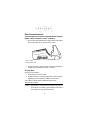
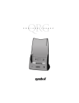
Introduction
This guide presents information on the installation and use of the
VCD 7500 vehicle cradle, used with Symbol’s PDT 7500
terminals.
The VCD 7500 supports floor or dash installation in a truck. Each
cradle includes a vehicle power supply capable of power
conditioning in an operating range of 10 - 48 volts.
About This Guide
This guide provides information on the following:
•
•
•
•
•
•
•
•
•
Parts of the VCD 7500 on page 2
Setting Up the VCD 7500 on page 3
Cradle Self Test on page 4
Inserting the Terminal in the Cradle on page 5
Battery Charging on page 6
Charging A Spare Battery on page 7
Data Communications on page 8
LED Indications on page 9
Troubleshooting on page 10.
1
V C D
7 5 0 0
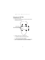
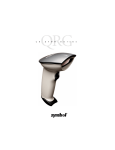
Parts of the VCD 7500
Terminal Capture/Release Hooks
Spare Battery
Charging Slot
Power Port
Power
Contacts
Serial Port
IrDA Port
Charge
LED
Communications
LED
2
Q u i c k
R e f e r e n c e
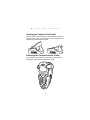
Setting Up the VCD 7500
To install the vehicle cradle:
1. Prepare the mounting surface to accept four #8-32 studs in
the pattern shown below.
1.188”
Holes for studs
min. 0.1660 in. diameter
(min. 4.25 mm diameter)
1.500”
2. Install the cradle on the mounting surface.
a. Position the cradle on the mounting surface.
b. Fasten using the hardware supplied.
3. Connect the red and black power supply input leads to a fuse
panel. A qualified installer must perform the installation.
3
V C D
7 5 0 0
4. Insert the power connector from the power supply in the power port on the side of the cradle.
Power Port
Cradle Self Test
On power up, the vehicle cradle performs a self-test which checks
the RAM and ROM. The Communications LED flashes during the
self-test. The vehicle cradle’s Communications LED reveals the
status as follows:
Communications LED
Condition
Status
Power up/Self-Test
(7 flashes -> off)
No error in RAM or ROM
LED flashing (8 flashes/second)
RAM test failure
LED flashing slowly
(4 flashes/second)
ROM (CRC on flash) failure
If the cradle fails self-test (RAM or ROM failure), power the cradle
down, then power on again. If the self-test fails again, call the
Symbol Support Center for assistance.
4
Q u i c k
R e f e r e n c e
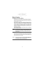
Inserting the Terminal in the Cradle
Insert the bottom of the terminal into the cradle slot and rest the
terminal on the hooks, then press the top of the terminal into the
cradle until the hooks snap into place.
Removing the Terminal from the Cradle
Press the left or right hook with your thumb until the terminal
disengages, and lift the terminal from the cradle.
5
V C D
7 5 0 0
Battery Charging
Charging the Terminal’s Battery
•
•
•
The lithium-ion (Li-Ion) battery is automatically recharged
whenever the terminal is properly inserted in the cradle. The
terminal may be on or off.
The terminal’s charge LED turns yellow while the terminal’s
battery pack is charging. Once charging is complete, the terminal’s charge LED turns green. If the terminal’s charge LED
is off, the terminal is not seated properly in the cradle. If the
terminal’s charge LED is blinking yellow, a faulty battery is installed in the terminal.
The terminal must be left in the cradle 2 hours to recharge a
fully discharged battery.
Caution:
•
The temperature range for charging the battery is 0°C50°C. Do not operate battery charger outside these
temperatures.
To remove the terminal from the VCD 7500, press the left or
right hook with your thumb until the terminal disengages, and
lift the terminal from the cradle.
Caution:
Removing the terminal while the cradle’s yellow communications LED is on or flashing disrupts communication between the host and the terminal.
6
Q u i c k
R e f e r e n c e
Charging A Spare Battery
To charge a spare battery, place the battery into the spare battery
charging slot by inserting the bottom of the battery into the slot
first, then snapping the top in.
Note:
Spare batteries can only be inserted and removed
when the terminal is not in the VCD 7500 cradle.
The cradle’s charge LED remains off when no battery is present in
the battery slot. During charging of a battery, the cradle’s charge
LED turns solid yellow. The battery requires up to 5 hours to fully
charge. Once charging is complete, the cradle’s charge LED turns
solid green. The charge LED flickers for approximately one
second every ten minutes that a fully charged battery is present in
the spare battery slot, while the charger performs a self-check.
If a fault condition is encountered, charging stops and the charge
LED blinks yellow approximately twice per second. The fault may
be due to a faulty battery, or it may be caused by any momentary
loss of contact between the battery and the cradle. Within
approximately ten minutes of encountering a fault, the cradle
performs a self-check. If the battery is not faulty, charging will
resume as above. If the battery is faulty, the charge LED may turn
yellow as if charging, but will eventually blink yellow again. For a
faulty battery, this cycle will repeat until the battery is removed
from the spare battery slot.
7
V C D
7 5 0 0
Data Communications
Connecting the Serial Cable to Symbol Mobile Gateway
(SMG), a Host Computer, Printer, or Modem
1. Plug a 9-pin serial cable into the communication port located
next to the power port on the side of the cradle.
Serial
Communication Port
2. Connect the other end of the cable to the serial (COM) port
of SMG, the host computer, printer, or modem.
Sending Data
To begin communication:
1. Insert the terminal in the cradle.
2. As determined by your specific application, press the appropriate key(s) on the terminal to initiate communication.
The cradle’s Communications LED blinks yellow when
communication begins.
Caution:
Removing the terminal while the cradle’s Communications LED is on or flashing yellow disrupts communication between the host and the terminal.
8
Q u i c k
R e f e r e n c e
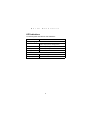
LED Indications
The following table describes the LED indications.
Condition
LED State
Battery Charging LED
Off
Spare battery absent, no charge power, or outside temperature range required for charging battery.
Steady yellow
Spare battery is charging.
Steady green
Spare battery is charged.
Flashing yellow
Abnormal battery.
Communications LED
Off
Terminal is not trying to communicate.
On (yellow)
Terminal is able to send and receive data.
9
V C D
7 5 0 0
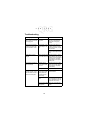
Troubleshooting
Symptom
Possible Cause
Yellow indicators do not
flash 7 times when the cradle is plugged in.
Cradle is not receiving power.
Make sure power cable is
securely connected and
wall outlet is supplying
power.
Action
Cradle charge LED does
not light when spare battery is inserted in cradle.
Spare battery is not
seated firmly in cradle.
Replace spare battery in
cradle; contacts snap into
place when battery is properly inserted.
Check for damaged contacts in cradle spare battery
slot.
Spare battery not fully
charged.
Battery was removed
from cradle too soon.
Replace battery in cradle
spare battery slot. Approximately 5 hours are needed
to recharge a completely
dead battery in the spare
battery slot.
Li-Ion battery in terminal
did not recharge.
Terminal was removed from cradle
too soon.
Replace terminal in cradle;
about 2 hours are needed
to recharge a completely
dead battery.
Battery failed.
Replace battery.
Terminal was removed from cradle
while yellow Communications LED
was blinking.
Replace terminal in cradle
and retransmit.
Null modem was not
used.
Null modem is required for
communication to DTE devices. Retransmit using appropriate null modem.
Incorrect null modem
configuration.
See your system administrator.
No data was transmitted to
the host or printer, or the
data transmitted to host or
printer was incomplete.
10
Q u i c k
R e f e r e n c e
11
V C D
7 5 0 0
Regulatory Information
All Symbol devices are designed to be compliant with rules and regulations in
locations they are sold and will be labeled as required.
Any changes or modifications to Symbol Technologies equipment, not expressly
approved by Symbol Technologies, could void the user’s authority to operate the
equipment.
Radio Frequency Interference Requirements
Tested to comply
with FCC Standards
FOR HOME OR OFFICE USE
Note: This equipment has been tested and found to comply with the limits for a Class
B digital device, pursuant to Part 15 of the FCC rules. These limits are designed to
provide reasonable protection against harmful interference in a residential
installation. This equipment generates, uses and can radiate radio frequency energy
and, if not installed and used in accordance with the instructions, may cause harmful
interference to radio communications. However there is no guarantee that
interference will not occur in a particular installation. If this equipment does cause
harmful interference to radio or television reception, which can be determined by
turning the equipment off and on, the user is encouraged to try to correct the
interference by one or more of the following measures:
• Reorient or relocate the receiving antenna
• Increase the separation between the equipment and receiver
• Connect the equipment into an outlet on a circuit different from that to which the
receiver is connected
• Consult the dealer or an experienced radio/TV technician for help.
Radio Frequency Interference Requirements - Canada
This Class B digital apparatus complies with Canadian ICES-003.
Cet appareil numérique de la classe B est conforme à la norme NMB-003 du Canada.
Marking and European Economic Area (EEA)
Statement of Compliance
Symbol Technologies, Inc., hereby declares that this device is in compliance with all
the applicable Directives, 89/336/EEC, 73/23/EEC. A Declaration of Conformity may
be obtained from http://www2.symbol.com/doc/.
12
Q u i c k
R e f e r e n c e
Warranty
(A) Seller’s hardware Products are warranted against defects in workmanship and
materials for a period of three (3) months from the date of shipment, provided the
Product remains unmodified and is operated under normal and proper conditions.
Warranty provisions and durations on software, integrated installed systems, Product
modified or designed to meet specific customer specifications ("Custom Products"),
remanufactured products, and reconditioned or upgraded products, shall be as
provided in the applicable Product specification in effect at the time of purchase or in
the accompanying software license. (B) Products may be serviced or manufactured
with parts, components, or subassemblies that originate from returned products and
that have been tested as meeting applicable specifications for equivalent new
material and Products. The sole obligation of Seller for defective hardware Products
is limited to repair or replacement (at Seller’s option) on a "return to service depot"
basis with prior Seller authorization. Shipment to and from Seller will be at Seller’s
expense, unless no defect is found. No charge will be made to Buyer for replacement
parts for warranty repairs. Seller is not responsible for any damage to or loss of any
software programs, data or removable data storage media, or the restoration or
reinstallation of any software programs or data other than the software, if any,
installed by Seller during manufacture of the Product. The aforementioned provisions
do not extend the original warranty period of any Product that had either been
repaired or replaced by Seller. (C) The above warranty provisions shall not apply to
any Product (i) which has been repaired, tampered with, altered or modified, except
by Seller’s authorized service personnel; (ii) in which the defects or damage to the
Product result from normal wear and tear, misuse, negligence, improper storage,
water or other liquids, battery leakage or failure to perform operator handling and
scheduled maintenance instructions supplied by Seller; (iii) which has been subjected
to unusual physical or electrical stress, abuse, or accident, or forces or exposure
beyond normal use within the specified operational and environmental parameters
set forth in the applicable Product specification; nor shall the above warranty
provisions apply to any expendable or consumable items, such as batteries, supplied
with the Product. EXCEPT FOR THE WARRANTY OF TITLE AND THE EXPRESS
WARRANTIES STATED ABOVE, SELLER DISCLAIMS ALL WARRANTIES ON
PRODUCTS FURNISHED HERUNDER INCLUDING ALL IMPLIED WARRANTIES
OF MERCHANTABLILTY AND FITNESS FOR A PARTICULAR USE. ANY IMPLIED
WARRANTIES THAT MAY BE IMPOSED BY LAW ARE LIMITED IN DURATION TO
THE LIMITED WARRANTY PERIOD. SOME STATES OR COUNTRIES DO NOT
ALLOW A LIMITATION ON HOW LONG AN IMPLIED WARRANTY LASTS OR THE
EXCLUSION OR LIMITATION OF INCIDENTAL OR CONSEQUENTIAL DAMAGES
FOR CONSUMER PRODUCTS. IN SUCH STATES OR COUNTIRES, FOR SUCH
PRODUCTS, SOME EXCLUSIONS OR LIMITATIONS OF THIS LIMITED
WARRANTY MAY NOT APPLY. The stated express warranties are in lieu of all
obligations or liabilities on the part of Seller for damages, including but not limited to,
special, indirect or consequential damages arising out of or in connection with the use
or performance of the Product or service. Seller’s liability for damages to Buyer or
others resulting from the use of any Product or service furnished hereunder shall in
no way exceed the purchase price of said Product or the fair market value of said
service, except in instances of injury to persons or property
13
Service Information
Before you use the unit, it must be configured to operate in your facility’s network and
run your applications.
If you have a problem running your unit or using your equipment, contact your facility’s
Technical or Systems Support. If there is a problem with the equipment, they will
contact the Symbol Support Center:
United States1
1-800-653-5350
1-631-738-2400
Canada
905-629-7226
United Kingdom
0800 328 2424
Asia/Pacific
+65-6796-9600
Australia
1-800-672-906
Austria/Österreich
1-505-5794-0
Denmark/Danmark
7020-1718
Finland/Suomi
9 5407 580
France
01-40-96-52-21
Germany/Deutchland
6074-49020
Italy/Italia
2-484441
Mexico/México
5-520-1835
Netherlands/Nederland
315-271700
Norway/Norge
+47 2232 4375
South Africa
11-8095311
Spain/España
Sweden/Sverige
84452900
Latin America
Sales Support
1-800-347-0178 Inside US
+1-561-483-1275 Outside US
Europe/Mid-East
Distributor Operations
Contact local distributor or call
+44 118 945 7360
1
91 324 40 00
Inside Spain
+34 91 324 40 00
Outside Spain
Customer support is available 24 hours a day, 7 days a week.
For the latest version of this guide go to:
http://www.symbol.com/manuals.
72-50160-01
Revision C — September 2002
Symbol Technologies, Inc. One Symbol Plaza Holtsville, NY 11742-1300