1
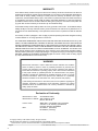
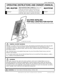
4800A NIC II LE L Tr a n sm it t er
INSTRUCTION 9550-9142
4888A-NIC II LEL
COMBUSTIBLE GAS
DETECTION TRANSMITTER
(Non-Intrusive Calibration)
C
US
Installation/Operation/Maintenance
Rev.5 – April 2008
ECN #129031
Delay /
Over-range
‘CAL’ Mode
Unity
Span
Fault / Keypad
0–100% LEL
COMBUSTIBLES
Zero
CAL
SCOTT HEALTH & SAFETY
4320 Goldmine Road, Monroe, NC 28110
Phone: 800-247-7257 • FAX: 704-291-8340 • Web: www.scotthealthsafety.com
Printed in U.S.A.
In st r u ct ion 9550-9142 Rev. 5
Scot t H ea lt h & Sa fet y
Page 1
4800A NIC II LE L Tr a n sm it t er
WARRANTY
Scott Health & Safety warrants to Buyer that at the time of delivery this Product will be free from defects in
material and manufacture and will conform substantially to Scott Health & Safety applicable specifications.
Scott Health & Safety's liability and Buyer’s remedy under this warranty are limited to the repair or
replacement, at Scott Health & Safety's option, of this Product or parts thereof returned to Seller at the factory
of manufacture and shown to Scott Health & Safety's reasonable satisfaction to have been defective;
provided that written notice of the defect shall have been given by Buyer to Scott Health & Safety within two
(2) years after the date of delivery of this Product by Scott Health & Safety.
Scott Health & Safety warrants to Buyer that it will convey good title to this Product. Scott Health & Safety's
liability and Buyer’s remedy under this warranty of title are limited to the removal of any title defects or, at
the election of Scott Health & Safety, to the replacement of this Product or parts thereof that are defective
in title.
The warranty set forth in paragraph 1 does not apply to parts the Operating Instructions designate as having
a limited shelf-life or as being expended in normal use.
THE FOREGOING WARRANTIES ARE EXCLUSIVE AND ARE GIVEN AND ACCEPTED IN LIEU OF (I) ANY
AND ALL OTHER WARRANTIES, EXPRESS OR IMPLIED, INCLUDING WITHOUT LIMITATION THE
IMPLIED WARRANTIES OF MERCHANTABILITY AND FITNESS FOR A PARTICULAR PURPOSE: AND (II)
ANY OBLIGATION, LIABILITY, RIGHT, CLAIM OR REMEDY IN CONTRACT OR TORT, WHETHER OR NOT
ARISING FROM SCOTT HEALTH & SAFETY'S NEGLIGENCE, ACTUAL OR IMPLIED. The remedies of the
Buyer shall be limited to those provided herein to the exclusion of any and all other remedies including,
without limitation incidental or consequential damages. No agreement varying or extending the foregoing
warranties, remedies or this limitation will be binding upon Scott Health & Safety unless in writing, signed
by a duly authorized officer of Scott Health & Safety.
WARNING!
Because this instrument is used to detect and monitor materials and conditions
which are listed by OSHA or others as potentially hazardous to personnel and
property, the information in this manual must be fully understood and utilized to
ensure that the instrument is operating properly and is both used and maintained
in the proper manner by qualified personnel. An instrument that is not properly
calibrated, operated and maintained by qualified personnel is likely to provide
erroneous information, which could prevent user awareness of a potentially
hazardous situation for the instrument user, other personnel and property.
If, after reading the information in this manual, the user has questions regarding the
operation, application or maintenance of the instrument, supervisory or training
assistance should be obtained before use. Factory assistance is available by
calling (704) 291-8300.
Declaration of Conformity
Manufacturer’s name:
Scott Health & Safety
Manufacturer’s address: 4320 Goldmine Road
Monroe, NC 28110
Product name:
EMC:
4888A-NIC II Combustible Gas Transmitter
conforms to the following specifications:
European Directive 89/336/EEC
EN 50081-1 (Emissions)
EN 50082-2 (Immunity)
© Copyright 1999 by Scott Health & Safety. All rights reserved.
®SCOTT HEALTH & SAFETY is a registered trademark of Scott Health & Safety.
All other brand or product names are trademarks or registered trademarks of their respective holders.
Page 2
A
Scot t H ea lt h & Sa fet y
In st r u ct ion 9550-9142 Rev. 5
4800A NIC II LE L Tr a n sm it t er
Contents
1 Introduction ................................................................................................................. 1
1.1 Transmitter Assembly Description ................................................................ 1
1.2 Transmitter Identification ............................................................................. 2
1.3 Features .......................................................................................................... 3
1.4 Operational Overview ..................................................................................... 4
2 Technical Data ............................................................................................................. 5
3 Installation ................................................................................................................... 7
3.1 Transmitter Location ..................................................................................... 7
3.2 Mounting the Transmitter ........................................................................... 10
4 Wiring .......................................................................................................................... 11
4.1 Wiring Overview .......................................................................................... 11
4.2 Meeting Electrical Codes .............................................................................. 11
4.3 Selecting Wire Size ....................................................................................... 12
4.3.1 4–20 Signal Loop Resistance ........................................................ 12
4.3.2 Power Supply Wire Length .......................................................... 12
4.4 Removing Housing Cover and Front Panel ................................................. 15
4.5 Detector Head Wiring .................................................................................. 16
4.6 Power Supply and Receiver Wiring ............................................................. 18
4.6.1 Setting the Transmitter’s Operating Voltage .............................. 18
4.6.2 Power Supply Wiring ................................................................... 18
4.6.3 Isolated and Non-Isolated 4–20 mA Output ................................. 18
4.6.4 Receiver Wiring ............................................................................ 18
4.6.5 Grounding and Shielding ............................................................. 21
4.7 Relay Board Wiring and Setup ................................................................... 21
4.7.1 Latching Alarms .......................................................................... 24
4.7.2 Normally Energized Alarms ........................................................ 24
4.7.3 Relay Trip Points ......................................................................... 24
4.8 Modbus RS-485 Board Wiring and Setup ..................................................... 25
4.8.1 RTU Address ................................................................................ 25
4.8.2 Modbus Data Registers and Function Codes ............................... 25
4.8.3 MODBUS Configuration Software ............................................... 28
4.8.4 RS-485 Wiring ............................................................................. 28
4.8.5 R4/47 End-of-Line Terminating Resistor.................................. 28
5 Calibration ................................................................................................................. 31
5.1 Calibration Intervals .................................................................................... 31
5.2 Preparing for Calibration ............................................................................. 31
5.3 Assembling the Calibration Fixture ............................................................. 32
5.4 Initial Start-Up ........................................................................................... 33
5.4.1 Input Voltage Check .................................................................... 33
5.4.2 Sensor Voltage Adjustment ......................................................... 34
5.4.3 Monitoring the VOUT Test Point ............................................... 36
5.4.4 Balance Adjustment .................................................................... 36
5.4.5 Initial Fixed Gain (JP1) Setting .................................................. 37
5.4.6 Completing Initial Start-Up ........................................................ 39
5.5 End-of-Service ............................................................................................... 39
In st r u ct ion 9550-9142 Rev. 5
Scot t H ea lt h & Sa fet y
Page 3
4800A NIC II LE L Tr a n sm it t er
5.5.1 Display Gain Service ................................................................... 40
5.5.2 Set End-of-Service Life Indicator ................................................ 40
5.6 Routine Calibration (Non-Intrusive) ........................................................... 41
5.7 4-20mA Simulate Mode ................................................................................ 43
6 Operation .................................................................................................................... 44
6.1 ‘Normal Mode’ Operation ............................................................................. 44
6.2 Fault Supervision ......................................................................................... 44
6.3 Overrange ..................................................................................................... 45
6.4 Sensor Flooding ............................................................................................ 45
6.5 Delay Modes .................................................................................................. 46
6.5.1 Power Up Delay ............................................................................ 46
6.5.2 ‘CAL’ Mode Exit Delay ................................................................. 46
6.5.3 Automatic ‘CAL’ Mode Exit Timer ............................................... 46
6.5.4 Aborting the Delay Modes ............................................................ 46
6.6 Calibration Values Back-Up Power ............................................................. 47
7 Maintenance .............................................................................................................. 48
7.1 Routine Maintenance .................................................................................... 48
7.2 Replacing the Combustibles Sensor ............................................................. 48
7.3 Transmitter Circuit Board Replacement ..................................................... 51
7.4 LCD Full Scale Display Adjustment ............................................................ 52
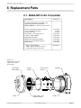
8 Replacement Parts .................................................................................................... 55
8.1 4888A-NIC II LEL Transmitter ................................................................... 55
8.2 Detector Head ............................................................................................... 56
8.3 Flow Cell Detector Head ............................................................................... 57
8.4 Duct Adapter Detector Head ........................................................................ 57
8.5 Accessories .................................................................................................... 57
8.6 Scott Health & Safety Sales/Service Centers ............................................... 58
APPENDIX “A” – Multiplying "K" Factors ................................................................. 59
APPENDIX “B” – Scott Health & Safety Series 6004, 6104 and 6800
Transmitter Wiring ................................................................................................ 63
APPENDIX “C” – 4888A-NIC II LEL Transmitter with P/N 40011600,
P/N 40009263, P/N 096-2678 or P/N 096-2679 5.5V Detector Assemblies ........... 67
Page 4
Scot t H ea lt h & Sa fet y
In st r u ct ion 9550-9142 Rev. 5
4800A NIC II LE L Tr a n sm it t er
Introduction
1 Introduction
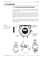
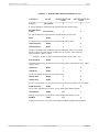
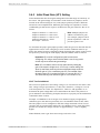
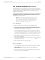
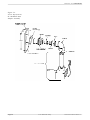
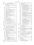
1.1 Transmitter Assembly Description
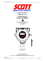
This manual describes how to install, operate, and maintain the Scott Health &
Safety 4888A-NIC II LEL Transmitter (Non-Intrusive Calibration), and associated
detector head (Figure 1-1).
The transmitter consists of a Front Panel/CPU assembly, one option board (if
installed), and an Input/Output board all housed in an explosion-proof aluminum
housing with viewing window. The transmitter operates from either 12 or 24 VDC,
and can drive virtually any configurable 4–20 mA receiving unit (DCS, PLC, loop
powered alarm, data logger, etc.) over three or four wires plus a conforming
ground.
There are three basic detector heads: diffusion, duct adapter, and flow cell. Variations of these heads include diffusion with calibration port, and flow cells with and
without an aspirator. Each of these detector heads contain a catalytic-bead, combustible-gas sensor.
LCD DISPLAY
PROVIDES LOCAL
READOUT OF GAS
LEVELS
MAGNET
TOOL
Delay /
Over-range
9550-0068
Figure 1-1.
4800-NIC LEL
Transmitter, with Magnet
Tool and Associated
Detector H ead s
‘CAL’ Mode
Unity
Span
Fault / Keypad
0–100% LEL
COMBUSTIBLES
Zero
CAL
MAGNETIC CONTROL
PANEL ALLOWS
NON-INTRUSIVE
CALIBRATION
TRANSMITTER
HOUSING
DIFFUSION
In st r u ct ion 9550-9142 Rev. 5
DUCT ADAPTER
Scot t H ea lt h & Sa fet y
FLOW CELL
Page 5
I n t r od u ct ion
4800A NIC II LE L Tr a n sm it t er
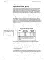
1.2 Transmitter Identification
A transmitter is identified by its model number, which in turn is determined by
what type of sensor, detector head, and output/option board are installed at the
time of manufacture. The transmitter’s model number is located on a label that is
attached to the side of the enclosure.
The diagram below shows how the transmitter’s model number is used to specify
its configuration.
For example: The model number 4888-1-1-1-2 denotes a transmitter with a combustibles sensor, an intergal diffusion detector head, and a 4–20 mA output with an
optional relay board.
4888-X X X X
Sensor Type
1 - Combustibles - 6V "Gold Bell" sensor
2 - 5.5V Scott bead (Stainless Steel Diffusion Head)
3 - 5.5V Scott Poison Resistant Bead (Stainless Steel Diffusion Head)
4 - 5.5V Scott bead (Stainless Steel Positive Flow Head)
5 - 5.5V Scott Poison Resistant Bead (Stainless Steel Positive Flow Head)
Detector Head
1 - Diffusion attached to housing
2 - Duct Adaptor
3 - Flow Cell w/ aspirator
4 - Remote Diffusion
w/calibration port
5 - Flow Cell w/o aspirator
6 - Remote Diffusion
7 - Round Duct Adaptor (4" or greater)
8 - No Option
Power Options
1 - 24VDC (Standard)
2 - 12VDC
Tran sm itte r Ou tpu t
1 - 4–20 mA Non-Isolated
2 - 4–20 mA Non-Isolated and Relays
3 - RS-485 Modbus
4 - 4–20 mA Isolated
All transmitter configurations are designed to be installed using explosion-proof
(XP) installation methods.
Page 6
Scot t H ea lt h & Sa fet y
In st r u ct ion 9550-9142 Rev. 5
4800A NIC II LE L Tr a n sm it t er
I n t r od u ct ion
1.3 Features
• Continuous, local LCD readout of combustible gas levels in the range of
0–100% LEL.
• Non-intrusive calibration (NIC) using a magnet tool, allowing the transmitter to
be calibrated in hazardous areas without area declassification.
• Three or four wire transmission, providing a standard 4 to 20 mA output signal.
• One-man calibration.
• The ability of being operated as a stand alone unit, or reporting to a host computer through commercial input/output processors.
• Indicators that show when the transmitter is warming up, in calibration, or in a
fault condition.
• Diagnostic output signals which distinguish between the transmitter’s calibration (1.5 mA), fault (0 mA) and overrange (20.5 mA) modes.
• An approved explosion proof aluminum transmitter enclosure with watertight Oring. The enclosure is coated with a hybrid epoxy powder/polyester paint for
superior chemical resistance. The 4888A-NIC II LEL Transmitter and its
detector assembly are suitable for installation in Class I, Division 1, Group B, C,
and D hazardous locations.
• Space is provided behind the Front Panel/CPU assembly to add a single circuit
board for adding one of the following optional functions:
- Relay Board provides local activation of WARN, ALARM, and FAIL annunciators for the purpose of alerting personnel of rising combustible gas levels or
system electrical failures.
- Modbus RS-485 Serial Interface Board allows up to 128 transmitters to
communicate to a Modbus master device over a single 2- or 4-conductor cable.
- Isolated 4–20 mA Output Board isolates the transmitter’s output from its
power supply and sensor circuits.
In st r u ct ion 9550-9142 Rev. 5
Scot t H ea lt h & Sa fet y
Page 7
I n t r od u ct ion
4800A NIC II LE L Tr a n sm it t er
1.4 Operational Overview
In operation, when a mixture of air and combustible vapors or gases surrounds the
detector head, the combustibles around the surface of the sensor’s active element
are rapidly oxidized (by catalytic oxidation), thus raising the temperature of that
element. This rise in temperature causes an increase in the resistance of the active
element in relation to the sensor’s inactive (reference) element.
The transmitter’s electronics measure the sensor’s change of resistance and
generates an output current of between 4 and 20 mA that is proportional to the
detected combustible gas level, where 4 mA represents 0% LEL, and 20 mA represents 100% LEL. In addition to the transmitter’s output signal, the LCD on the
unit’s faceplate, viewable through the explosion-proof enclosure’s transparent cover,
provides local display of the detected gas level in %LEL.
Calibration is performed at the transmitter without removing its explosion proof
viewing cover, making area declassification unnecessary. The only tool required for
this “non-intrusive” calibration is a small magnet, which is provided with the
transmitter.
ZERO and SPAN operations are performed by placing the transmitter into its
calibration mode by briefly holding the magnet tool over the CAL dot on the faceplate. The transmitter responds by causing the ‘CAL’ Mode arrow to light steadily.
The magnet serves as a “pass-key” which makes it difficult for unauthorized
personnel to tamper with the calibration settings. Calibration of the system is then
performed by applying calibration gas and holding the magnet over the
Zero and
Span symbols as required to obtain the correct readings. Once calibration is
complete, an E2 PROM provides backup to retain calibration settings during power
interruptions.
Page 8
Scot t H ea lt h & Sa fet y
In st r u ct ion 9550-9142 Rev. 5
4800A NIC II LE L Tr a n sm it t er
Tech n ica l Da t a
2 Technical Data
Readout ................................................ 3-½ digit LCD (% LEL)
Power Requirements ......................... 18.0 to 30.0 VDC; 4.2 watts maximum steady state @ 24 VDC
nominal input (with relay option board installed, relays
energized)
Sign al Ou tpu t ..................................... 4–20 mA into 800 ohms with 24 VDC power standard. Range of
operation is 0 to 20.5 mA.
Magnetic Calibration
Adjustment Range ............................. ZERO: ±15% of full scale.
SPAN: Turn up to gain of 2, down to gain of 0.5 (The sensor
can lose up to 50% of its signal strength, and the magnetic
SPAN adjustment can still be used to properly calibrate the
transmitter without having to open the enclosure.)
Calibration Resolution ...................... 0.1% of full scale
Diagnostics .......................................... CAL mode: Lighted ‘CAL’ Mode arrow with the output held at
1.5 mA.
FAULT mode: Lighted Fault/Keypad LED with the output
held at 0 mA. A fault condition is detected if the sensor
develops an open or short circuit, or its output drifts far enough
negative to cause the 4–20 mA output signal to drop to 2.4 mA
(–10% of full scale).
Over-range mode: Over range arrow flashes 3–4 times a
second with the output held at 20.5 mA, until the over-range
condition clears.
ESL: ESL will flash on display every 10 seconds when trip
point is exceeded during calibration.
Memory Backup ................................. E 2 PROM device retains calibration settings during power
interruptions.
Housing ................................................ Transmitter electronics is housed in an HKB-style explosionproof aluminum enclosure with watertight O-ring. Hazardous
area rating: Class I, Div. 1, Groups B, C and D.
Accuracy (electronics) ....................... ±0.1% of full scale, ±1 count
Ambient Temperature:
Transmitter electronics ............. – 40 to 158 °F (– 40 to 70 °C)
N ote th at th e tran sm itter’s low -en d tem peratu re perform an ce
is based on self-h eatin g of th e electron ics by h avin g th e cover
in place and power applied for at least 1 hour prior to
evaluating performance .
Combustibles Sensor .................. – 40 to 200°F (– 40 to 93°C) 6 Volt Detector
– 40 to 400°F (– 40 to 200°C) 5.5 Volt Detector
Temperature Drift ............................. Less than 0.1% per °C over ambient temperature range
In st r u ct ion 9550-9142 Rev. 5
Scot t H ea lt h & Sa fet y
Page 9
Tech n ica l Da t a
4800A NIC II LE L Tr a n sm it t er
Response Time .................................... <10 seconds to 50% full scale
<30 seconds to 90% full scale
Dimensions .......................................... See Figure 3-4
Weight ................................................... Transmitter Assembly
Diffusion Detector
Flow Cell Detector
Duct Adapter Detector
–
–
–
–
3 lb 8 oz (1.6 kg)
8 oz (0.2 kg)
14 oz (0.4 kg)
1 lb 9 oz (0.7 kg)
Sensor:
Type ................................................ Catalytic (platinum bead), 6 volt operation
Life Expectancy ........................... 1 year normal service when intermittently exposed to
combustible gas-in-air mixtures
Catalyst “Poisoning” ................... Do not expose catalytic sensor to silicone vapor or silicone
compounds that outgas before fully curing. Consult factory for
further details.
Hazardous Area Rating ................... CSA — Explosion proof installation,
Class I, Division 1, Groups B, C and D
Hazardous Location C22.2 No. 152
CSA/US — CSA has accreditation in U.S. from Occupational
Safety and Health Administration (OSHA) as a nationally
recognized testing laboratory.
Relay Board Option:
Contact Rating ............................. Relay contacts are SPDT, Form C, rated for:
5A @ 250 VAC / 30 VDC (resistive)
Typical Alarm Se ttin gs .............. 20% LEL WARN level (Alarm 1)
40% LEL ALARM level (Alarm 2)
Controls ......................................... DIP switch determines setting of eight board functions;
Two rotary switches set the WARN and ALARM trip points
4–20 m A Ou tpu t Board Option ....... 1500 V isolation between the 4–20 mA output signal and the
transmitter’s power supply
RS-458 Serial Board Option ............. Modbus protocol
Page 10
Scot t H ea lt h & Sa fet y
In st r u ct ion 9550-9142 Rev. 5
4800A NIC II LE L Tr a n sm it t er
Installation
3 Installation
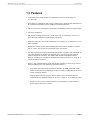
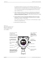
3.1 Transmitter Location
Mount the transmitter with its detector head facing downward, where it can be
calibrated and maintained safely and easily. Leave enough clearance for service
personnel to make adjustments or repairs. When planning the installation, remember that 3 /4 " conduit will need to run from the transmitter to its receiving equipment, and, if the optional relay board is installed, from the transmitter to the
WARN, ALARM and FAIL annunciators and their power source. See Figure 3-1.
When in doubt about where to mount the transmitter, we recommend that you
consult a professional safety engineering firm.
Generally, for accurate combustible gas detection, install the 4888A-NIC II LEL
Transmitter and its attached detector head:
• Where air currents contain high concentrations combustible gas. Mount near
the floor for heavier-than-air gases, or near the ceiling or roofs for lighter-thanair gases.
• In areas within the operating temperature range of the transmitter — refer to
Section 2 Technical Data. If the area is subject to temperature extremes, protect
the transmitter by choosing a “friendly” mounting location where natural
protection is available to shade, reduce, or nullify the adverse temperature
condition.
• Away from the direct destructive effects of corrosive agents, moisture, dust and
dirt, if possible. Take precautions to prevent any blockage or freeze-over of the
gas-diffusion path.
• In an area where the transmitter can be calibrated and maintained in a safe and
easy manner. Leave enough clearance for service personnel to make adjustments
or repairs.
Figure 3-1.
Typical Transmitter,
showing a Diffusion
Detector H ead
Delay /
Over-range
‘CAL’ Mode
Unity
Span
Fault / Keypad
0–100% LEL
COMBUSTIBLES
Zero
CAL
3/4-NPT Conduit
used for power,
4–20 mA signal, and
optional relay board
or modbus wiring.
If second conduit
opening is not
required, seal unused
opening with pipe
plug supplied with
transmitter.
Diffusion Detector Head
"Gold Bell" Type
In st r u ct ion 9550-9142 Rev. 5
Scot t H ea lt h & Sa fet y
Page 11
Installation
4800A NIC II LE L Tr a n sm it t er
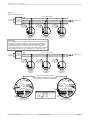
Figure 3-2 shows typical mounting of the flow cell and duct adapter detector heads
(detailed mounting instructions of the flow cell detector are supplied in Instruction
51-9098).
Figure 3-2.
Typical Flow Cell and Duct
A d apter Detector H ead
Locations
FLOW CELL w/ASPIRATOR
DUCT ADAPTER
Page 12
Scot t H ea lt h & Sa fet y
In st r u ct ion 9550-9142 Rev. 5
4800A NIC II LE L Tr a n sm it t er
Installation
Figure 3-3 shows installation of a diffusion detector head mounted separate from
the transmitter (106 foot maximum separation) in areas where it is not convenient
to have both units together.
Figure 3-3.
Typical Diffusion Head
Mounting Locations when
Separated from the
Transmitter Housing
In st r u ct ion 9550-9142 Rev. 5
Scot t H ea lt h & Sa fet y
Page 13
Installation
4800A NIC II LE L Tr a n sm it t er
3.2 Mounting the Transmitter
Mount the transmitter on a vertical surface, in the area determined from Section
3.1 T ran sm itter L ocation .
Choose appropriate #10 hardware that will safely secure the transmitter and its
two 1-¼" standoffs (P/N 51-1329) on the mounting surface. Note that if the detector
head is being located separate from the housing, then the standoffs are not required. Refer to Section 2 Technical Data to determine the combined weight of the
transmitter and detector head. Mounting dimensions are shown in Figure 3-4.
The general mounting procedure is to place the transmitter where it will be
mounted; mark the positions of its two mounting holes; predrill the mounting
holes; then use #10 hardware to secure the transmitter and its standoffs (if used) to
the supporting structure.
Figure 3-4.
T ran sm itter an d Detector
Head Outline and
Mounting Dimensions
3/4-NPT
Conduit
Connection
(3 Places)
4.53"
(11.5 cm)
5.5"
(14 cm)
1.25"
(3.2 cm)
Delay /
Over-range
Fault / Keypad
‘CAL’ Mode
CAL
0.25" (6.35 mm) Mounting
Hole Accepts #10 Hardware
(2 places)
"Gold Bell"
Detector Head
Page 14
Zero
5.25"
(13.3 cm)
Span
STANDOFF
51-1329
(2 supplied)
8.55"
(21.7 cm)
Unity
Scot t H ea lt h & Sa fet y
In st r u ct ion 9550-9142 Rev. 5
4800A NIC II LE L Tr a n sm it t er
Wir in g
4 Wiring
4.1 Wiring Overview
WARNING!
B e su re to d eclassify th e area to n on -h azard ou s before open in g
th e tran sm itter or an y oth er electrical en closu res. T h en ch eck
th e area for th e presen ce of com bu stibles w ith a portable gas
d et ect or.
Wire the 4888A-NIC II LEL Transmitter to:
• Its detector head.
• A power source that will supply between 18–30 VDC at the input of the transmitter. The power source must be well filtered and regulated, and of sufficient
quality to provide a reasonable degree of protection. (10–18 VDC operation is also
possible. Refer to Section 4.6.1.)
• Equipment capable of receiving the transmitter’s standard 4–20 mA output
signal (e.g., PLC, DCS, loop powered alarm, data logger, etc.).
• Optional WARN, ALARM and FAIL annunciators (e.g., bells, buzzers, strobe
lights, etc.) which function to alert personnel of rising gas levels and transmitter
electrical malfunctions.
• Optional Modbus RS-485 master which functions to retrieve information from up
to 128 transmitters using either 4 wire full duplex, or 2 wire half duplex connections.
4.2 Meeting Electrical Codes
WARNING!
T o avoid an explosion or electrical fire, en case th e cable con n ection to th e tran sm itter in con d u it. T h e con d u it m u st m eet
prevailing electrical codes for hazardous-area installations
which specify conduit sealing, explosion-proof fittings, and
special wiring methods.
To meet prevailing electrical codes, use conduit and all other materials required for
electrical wiring in hazardous areas. Install wiring according to National Electrical
Code (NEC) Articles 501-517.
As supplied, the detector head’s wiring is already sealed and requires no additional
sealing to conform to NEC requirements for explosion-proof installations, as long as
the detector is mounted no further than 18" (457 mm) from the transmitter [NEC
Article 501-5(a)(1)].
In st r u ct ion 9550-9142 Rev. 5
Scot t H ea lt h & Sa fet y
Page 15
Wir in g
4800A NIC II LE L Tr a n sm it t er
4.3 Selecting Wire Size
4.3.1 4–20 Signal Loop Resistance
The maximum signal-loop resistance that can be connected to the transmitter’s
output is 800 ohms @ 24 VDC (400 ohms @ 12 VDC). In almost all cases, the wire
size chosen for the power supply leads will be more than adequate for the 4–20 mA
signal lead. Note that 18 AWG wire provides a 4–20 mA signal lead wiring distance of approximately 34,000 feet!
Note: Maximum signal-loop resistance is defined as the sum of
th e 4–20 m A sign al-w ire resistan ce, th e receiver’s in pu t resistan ce (n orm ally 250 oh m s), an d th e resistan ce of th e com m on
grou n d w ire betw een th e tran sm itter an d pow er su pply.
4.3.2 Power Supply Wire Length
The transmitter requires an operating voltage of between either 10–18 or
18–30 VDC, as determined by the installation of a jumper at J04 on the Input/
Output board. Use a power supply that provides a voltage within the appropriate
range at the transmitter after taking into consideration the “IR” drop of the power
supply leads as described below. The transmitter’s terminal block can accept wire
sizes of up to 14 AWG; however, 16 or 18 AWG should be sufficient for most
installations.
The minimum AWG wire size that can be used to connect the power supply to the
transmitter is determined by the output voltage of the power supply, the maximum
current drawn by the transmitter, and the voltage drop that occurs across the
wiring.
When choosing the location of the transmitter and its power supply, the size and
length of the power supply wires become an issue if the wiring’s voltage drop would
cause the transmitter’s input voltage to drop below its minimum operating voltage.
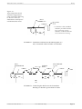
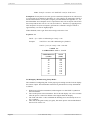
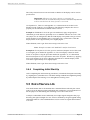
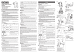
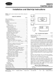
The following graphs are provided as an aid in determining maximum wiring
distances for various power supply voltages and wire sizes. To determine the
maximum wiring distance, first calculate the wiring’s maximum allowable voltage
drop by subtracting the transmitter minimum operating voltage (either 10 or
18 VDC) from the power supply’s output voltage. Then use the appropriate graph to
determine the maximum wiring distance for 18, 16 and 14 AWG wire.
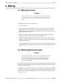
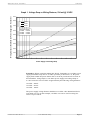
Note that Graph 1 is based on a worse case transmitter current of 234 mA at
18 VDC, while Graph 2 is based on a current of 420 mA at 10 VDC. Both graphs
are based on a temperature of 85 °C, and take into consideration that the wiring
distance consists of two wires (both hot and return). The graphs are invalid,
however, if the wire being used has a different ohms/foot value from that listed.
If your wiring requirements fall outside the boundaries of the graph, then use
Equation 4-1 to calculate the maximum wire length.
Page 16
Scot t H ea lt h & Sa fet y
In st r u ct ion 9550-9142 Rev. 5
4800A NIC II LE L Tr a n sm it t er
Ca libr a t ion
Wiring Distance (Feet) Between Power Supply and Transmitter
Graph 1. Voltage Drop vs. Wiring Distance, 234 mA @ 18 VDC
9000
8000
14AWG
16AWG
7000
18AWG
Ohms/Foot
14 AWG
16 AWG
18 AWG
6000
5000
Values:
0.00314
0.00591
0.00802
4000
3000
2000
1000
0
0
1
2
3
4
5
6
7
8
9
10
11
12
Power Supply Lead Voltage Drop
Example 1: When wiring the 4888A-NIC II LEL Transmitter to a 24 VDC power
supply (transmitter setup for 18–30 VDC operation per Section 4.6.1), the power
supply leads cannot drop more than 6 VDC in order to provide at least 18 VDC at
the transmitter. Using Graph 1, note that a power supply lead voltage drop of
6 volts crosses the wire size lines at approximately the following wiring distances:
14 AWG – 4050 ft
16 AWG – 2150 ft
18 AWG – 1600 ft
The power supply wiring distance should not exceed the value determined for its
associated wire size. In this example, 18 AWG wire can be used for wiring distances of up to 1600 ft.
In st r u ct ion 9550-9142 Rev. 5
Scot t H ea lt h & Sa fet y
Page 17
Wir in g
4800A NIC II LE L Tr a n sm it t er
Wiring Distance (Feet) Between Power Supply and Transmitter
Graph 2. Voltage Drop vs. Wiring Distance, 420 mA @ 10 VDC
3500
14AWG
3000
16AWG
18AWG
2500
Ohms/Foot
14 AWG
16 AWG
18 AWG
2000
Values:
0.00314
0.00591
0.00802
1500
1000
500
0
0
1
2
3
4
5
6
7
8
Power Supply Lead Voltage Drop
Example 2: When wiring the 4888A-NIC II LEL Transmitter to a 12 VDC power
supply (transmitter setup for 10–18 VDC operation per Section 4.6.1), the power
supply leads cannot drop more than 2 VDC in order to provide at least 10 VDC at
the transmitter. Using Graph, note that a power supply lead voltage drop of 2 volts
crosses the wire size lines at approximately the following wiring distances:
14 AWG – 760 ft
16 AWG – 400 ft
18 AWG – 300 ft
The power supply wiring distance should not exceed the value determined for its
associated wire size. In this example, 18 AWG wire can be used for wiring distances of up to 300 ft.
Page 18
Scot t H ea lt h & Sa fet y
In st r u ct ion 9550-9142 Rev. 5
4800A NIC II LE L Tr a n sm it t er
Wir in g
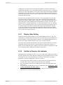
Equation 4-1. Wiring Distance
Dir =
VPower Supply – VMin
Where:
IMax x RWire x 2
D ir = Maximum wire length in feet based on
the wire’s loop voltage (IR) drop
VPower Supply = Power Supply output voltage
VMin = Minimum operating voltage of
transmitter
I Max = Maximum current in amperes
R Wire = Resistance of wire in ohms/foot
Example 3: When wiring the 4888A-NIC II LEL Transmitter that is configured
for 10-18 VDC operation to a 16 VDC power supply, the power supply leads cannot
drop more than 6 VDC in order to provide at least 10 VDC at the transmitter.
Using Equation 4-1, the maximum wiring distance for 18 AWG wire is:
Dir =
16 – 10
0.42 x 0.00802 x 2
= 890 ft.
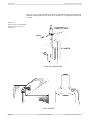
4.4 Removing Housing Cover
and Front Panel
To access the wiring terminal blocks inside the transmitter housing, remove the
housing cover and front panel as follows:
1. Loosen locking screw on housing cover using a 7 /64" hex wrench; then unscrew
and remove cover.
2. Loosen the two captive thumb screws on the front panel assembly; then lift out
the front panel with its circuit boards attached as far as allowed by the ribbon
cable.
3. After wiring is complete, replace the front panel assembly by aligning its two
thumb screws with their mating standoffs and firmly hand tighten.
4. Replace the housing cover and tighten its locking screw.
In st r u ct ion 9550-9142 Rev. 5
Scot t H ea lt h & Sa fet y
Page 19
Wir in g
4800A NIC II LE L Tr a n sm it t er
4.5 Detector Head Wiring
Each 6 Volt detector head assembly is supplied with 18" of wire, allowing it to be
mounted on the transmitter housing either directly, or by a short section of ¾"
conduit per Figure 4-1 (Example 1). 5.5 Volt detectors are supplied with 6" of wire
for direct mounting to the transmitter housing. Note that the wiring attached to
the detector head is already sealed and requires no additional sealing to conform to
NEC requirements for explosion-proof installations, as long as the detector head is
mounted no further than 18" from the transmitter [NEC Article 501-5(a)(1)]. For
exceptions to this distance, read the label on the transmitter housing.
If the detector head is being mounted more than 18" from the transmitter (106 ft
max.) as shown in Figure 4-1 (Example 2), splice a three-conductor cable (preferably with black, red, and white wires) onto the detector head’s existing wiring as
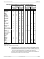
described below. The maximum distances between the detector head and transmitter for various wire sizes are listed in Table 4-1. The detector head’s safety-ground
wire must the same size as the other transmitter wires as determined from Section
4.3 S electin g Wire S ize.
The added detector-head wiring must meet prevailing electrical codes for hazardous-area installations that specify conduit sealing, explosion-proof fittings, and
special wiring methods.
TAB LE 4-1. MAXIMU M D IS TAN CE B ETWEEN
D ETECTOR AN D TRAN S MITTER
Note: Table 4-1 only applies
to the "Gold Bell" 6.0V bead
design. The 5.5V Scott
stainless steel head design
can be seperated up to
1,600 feet using 18 AWG wire.
AWG
Ohms/Foot
at 8 5 °C (1 8 5 °F )
12
14
16
18
0.0023
0.0031
0.0059
0.0080
Maximum
Distance
106'
80'
42'
31'
(38 m)
(24 m)
(13 m)
(9 m)
Note: Consult the factory if longer distances are
requ ired w h en th e tem peratu re betw een th e
tran sm itter an d th e d etector h ead is relatively
constant.
When installing conduit and wiring from the detector head to the transmitter
housing, see Figure 4-1 and follow the procedures listed below.
• If the detector head is mounted more than 18" from the transmitter, encase all
wire splices in a junction box. Also place conduit seals, Crouse-Hinds EYS 216
(or equivalent), between the transmitter housing and the junction box.
• Use AMP (or equivalent) parallel or butt type splices for all wire connections.
• Ground the junction box.
After mounting the detector head either on the transmitter housing or at its remote
location, trim off any excess wire and connect the detector head’s black, white, and
red wires to terminal block TB1 terminals R, C, and A on the Input/Output board
per Figure 4-2, 4-3, 4-4, or 4-5. The green wire serves as an earth ground that is
connected to the ground screw inside the transmitter enclosure.
Page 20
Scot t H ea lt h & Sa fet y
In st r u ct ion 9550-9142 Rev. 5
4800A NIC II LE L Tr a n sm it t er
Figure 4-1.
Typical Explosion Proof
Conduit Configurations
from Transmitter Housing
to Detector H ead for
Installation in Group B, C
and D Hazardous Areas
Wir in g
NIC II
* 18 inches is the standard
distance per NEC Articles.
For exception s to th is
distance, read the label on
th e tran sm itter h ou sin g.
EXAMPLE 1: Transmitter and Detector threaded together as a
unit, or mounted within 18 inches of each other
NIC II
TRANSMITTER
CONDUIT
SEALS
JUNCTION BOX
51-1330
EXAMPLE 2: Connecting the Detector to the Transmitter
Housing at a distance greater than 18 inches
In st r u ct ion 9550-9142 Rev. 5
Scot t H ea lt h & Sa fet y
Page 21
Wir in g
4800A NIC II LE L Tr a n sm it t er
4.6 Power Supply and Receiver Wiring
The transmitter can be connected to its power supply and receiver using individual
wires, but the recommended method is to use a multi-conductor overall shielded
cable. It is strongly recommended that the transmitter wiring not be run in
common conduit or raceways with AC power conductors or conductors servicing
raceway equipment that may generate RFI.
4.6.1 Setting the Transmitter’s Operating Voltage
The transmitter is normally configured for an operating voltage of 18–30 VDC;
however, 10–18 VDC operation is also possible by soldering a jumper at J04 on the
Input/Output board. The lower voltage setting is used when the transmitter is used
as a stand-alone unit with a 12 VDC power supply. The location of jumper J04 is
shown in Figures 4-4 and 4-5.
4.6.2 Power Supply Wiring
Following all wiring methods previously described for hazardous-area installations,
run wires of an appropriate AWG size (as determined from Section 4.3 Selecting
Wire Size) from the remote power supply to the transmitter housing. Connect the
“+” and “–” power supply leads to TB2 terminals PWR and GND on the Input/
Output board per Figure 4-2, 4-3, 4-4, or 4-5. Or refer to Appendix “B” if the
transmitter is being connected to an Sentinel VI, Sentinel 16 or Series 6800 Gas
Receiver.
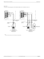
4.6.3 Isolated and Non-Isolated 4–20 mA Output
When the optional Isolated 4–20 mA Output board is installed, the output signal is
isolated from the transmitter’s power supply and sensor leads. Without this board
installed, the transmitter’s circuit boards, sensor, and output signal all share a
common power supply wire. Use the Isolated 4–20 mA Output board option if your
receiving equipment requires an isolated input.
Note that a transmitter with a non-isolated output requires 3 wires, while a
transmitter with an isolated output requires 4 wires. In both cases, a conforming
safety-ground wire is also required (shielding the ground wire is optional).
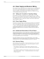
4.6.4 Receiver Wiring
If the transmitter will be reporting to a remote receiving device (e.g., PLC, DCS,
loop powered alarm, data logger, etc.), then connect the transmitter’s 4–20 mA
output to the receiving device as follows:
- For transmitter’s requiring a non-isolated output, connect the receiver’s
4–20 mA input to TB2 terminal OUT SIG on the Input/Output board per Figure 4-2.
- For transmitters requiring an isolated output, connect the receiver’s 4–20 mA
input to TB1 terminals “+” and “–” on the optional Isolated 4–20 mA Output
board per Figure 4-3.
Page 22
Scot t H ea lt h & Sa fet y
In st r u ct ion 9550-9142 Rev. 5
4800A NIC II LE L Tr a n sm it t er
Wir in g
Figure 4-2.
Transmitter Wiring Diagram, Non-Isolated 4–20 mA Output
WIRE NUT
INSIDE
HOUSING
HOUSING
GROUND
SCREW
4 – 20 mA
+
(DCS, PLC, etc.)
–
RECEIVER
GROUND (GRN)
REFERENCE (BLACK)
+
–
COMMON (WHITE)
COMMON
GND (COMMON)
R
C
TB2 JP1
TO
COMBUSTIBLES
DETECTOR
HEAD
"GOLD BELL"
6V TYPE
Note: See Appendix C when
using the 5.5V Scott Stainless
Steel Catalytic Bead.
A
TB1
SPARE
JUMPERS
EARTH GROUNDS
NEAR POWER
SUPPLY
OUT SIG
ACTIVE (RED)
PWR
24 VDC
POWER
SUPPLY
+POWER
VOLTS
12 34
BAL
J04INPUT
/ OUTPUT BOARD
Figure 4-3.
Transmitter Wiring Diagram, Isolated 4–20 mA Output
WIRE NUT
INSIDE
HOUSING
+
(DCS, PLC, etc.)
–
HOUSING
GROUND
SCREW
4 – 20 mA
RECEIVER
GROUND (GRN)
REFERENCE (BLACK)
+
–
+POWER
COMMON (WHITE)
COMMON
ACTIVE (RED)
R
RIBBON CABLE TO
I/O PCB
TB2 JP1
TB1
A
VOLTS
12 34
BAL
J04INPUT
+
C
TO SENSOR
"GOLD BELL"
6V TYPE
TB1
OUT SIG
PWR
SPARE
JUMPERS
EARTH GROUNDS
NEAR POWER
SUPPLY
GND (COMMON)
24 VDC
POWER
SUPPLY
/ OUTPUT BOARD
Note: See Appendix C when
using the 5.5V Scott Stainless
Steel Catalytic Bead.
–
ISOLATED
4-20mA
OUTPUT
ISOLATED 4–20 mA OUTPUT BOARD
In st r u ct ion 9550-9142 Rev. 5
Scot t H ea lt h & Sa fet y
Page 23
Wir in g
4800A NIC II LE L Tr a n sm it t er
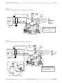
Figure 4-4.
Transmitter Wiring Diagram, Stand-Alone Operation, Local Readout Only
WIRE NUT
INSIDE
HOUSING
HOUSING
GROUND
SCREW
EARTH GROUNDS
NEAR POWER
SUPPLY
GROUND (GRN)
REFERENCE (BLACK)
+POWER
COMMON (WHITE)
COMMON
GND (COMMON)
R
C
TO SENSOR
"GOLD BELL"
6V TYPE
A
TB1
OUT SIG
ACTIVE (RED)
SPARE
JUMPERS
+
–
PWR
12 / 24 VDC
POWER
SUPPLY
TB2 JP1
VOLTS
12 34
BAL
J04
Convert to 10–18 VDC
operation by soldering
a jumper wire at J04
Note: See Appendix C when
using the 5.5V Scott Stainless
Steel Catalytic Bead.
INPUT / OUTPUT BOARD
Figure 4-5.
Integrated Transmitter Wiring Diagram, Bacharach System 130
WIRE NUT
INSIDE
HOUSING
HOUSING
GROUND
SCREW
4 – 20 mA
GROUND (GRN)
REFERENCE (BLACK)
DET PWR +
COMMON (WHITE)
DET PWR –
GND (COMMON)
R
C
TO
COMBUSTIBLES
DETECTOR
HEAD
"GOLD BELL"
6V TYPE
A
TB1
OUT SIG
SPARE
JUMPERS
EARTH GROUNDS
NEAR SYSTEM 130
ENCLOSURE
ACTIVE (RED)
PWR
TO
SYSTEM 130
INTERFACE BOARD
(51-1797, 51-1800,
or 511906)
TB2 JP1
12 34
VOLTS
BAL
J04
Note: See Appendix C when
using the 5.5V Scott Stainless
Steel Catalytic Bead.
To operate transmitter
from the 16 VDC power
supply of a System 130,
connect a jumper wire
to J04
INPUT / OUTPUT BOARD
Page 24
Scot t H ea lt h & Sa fet y
In st r u ct ion 9550-9142 Rev. 5
4800A NIC II LE L Tr a n sm it t er
Wir in g
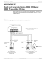
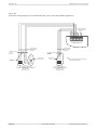
- For transmitters being connected to an Scott Health & Safety Series 6004 Quad
Scan, Series 6104 Panel Mount Quad Scan, or Series 6800 Gas Receiver, refer to
Appendix “B”.
4.6.5 Grounding and Shielding
Following all wiring methods previously described for hazardous-area installations,
connect a conforming safety-ground wire per local code from the transmitter’s
ground screw to an earth ground near the power supply / receiving equipment. The
ground wire must be no smaller than the largest current carrying transmitter
wire. Shielding the ground wire is optional.
Connect the shield of the transmitter wires to an earth ground near the power
supply / receiving equipment. Do not ground both ends of the shield!
4.7 Relay Board Wiring and Setup
The optional relay board provides contact closures for the activation of local annunciators (e.g., horns, bells, buzzers or lights) for the purpose of alerting personnel of
ALARM 1, ALARM 2, and ALARM 3 (WARN, ALARM, FAIL) conditions.
ALARM 3 is typically a fail safe FAIL relay, and is tripped by a defective sensor, or
if the 4–20 mA output has drifted below –10% of full scale. Since a FAIL relay is
normally energized (relay de-energizes under a fault condition), this alarm also
indicates loss of power to the transmitter. If the FAIL relay is not required, it is
possible to configure the ALARM 3 relay to trip with ALARM 2. This configuration
is useful if ALARM 2 is to drive an audible device, which needs to be
acknowledgeable, but another ALARM 2 relay is needed for driving another
non-acknowledgeable device such as a fan.
The ALARM 1 and ALARM 2 relays activate their associated annunciators when
the gas level rises above predetermined trip-points. These trip-points are set by
each relay’s associated 16-position rotary switch. The ALARM 1 and ALARM 2
relays can be made to function in the following manner as determined by the
FUNCTION DIP switch:
• Increasing Trip: Action occurs when the gas level rises above the trip-point.
• Decreasing Trip: Action occurs when the gas level falls below the trip-point.
• Non-Latch: Annunciator automatically turns off then the gas level falls below the
trip-point.
• Latch: Annunciator remains on even if the gas level falls below the trip-point.
Once activated, the annunciator must be manually reset by either closing a
remote switch connected to TB4 on the relay board as shown in Figure 4-6, or by
holding a magnet near the transmitter’ enclosure per Figure 4-7.
In st r u ct ion 9550-9142 Rev. 5
Scot t H ea lt h & Sa fet y
Page 25
Wir in g
4800A NIC II LE L Tr a n sm it t er
• De-energized: The relay is de-energized under normal operating conditions, and
becomes energized when the gas level exceeds the trip-point.
• Energized: The relay is energized under normal operating conditions, and
becomes de-energized when the gas level exceeds the trip-point. The normally
energized operating mode may also be referred to as “fail-safe.”
• Acknowledge: The ALARM 2 (ALARM level) annunciator can be turned off by
activating the local magnetic or remote RESET switch (Alarm 2 condition
acknowledged; horn silenced) when the gas level is still above its trip-point.
• No Acknowledge: The ALARM 2 annunciator cannot be reset until the gas level
drops below its trip-point.
• A3 FAIL: Operate the ALARM 3 relay in its FAIL mode (normally energized). For
gas detection applications, A3 should always be operated as a FAIL relay.
• Trips with A2: Operate the ALARM 3 relay in conjunction with ALARM 2.
Connect the annunciators to their own power source — DO NOT use the
transmitter’s power supply to power the annunciators. Also make certain that the
annunciator’s power source is properly fused.
Run wires of a suitable AWG size, according to NEC and any appropriate local
electrical codes, from each annunciator to Terminal Blocks A1, A2 and A3. Use the
annunciator’s power consumption rating to determine wire size and fuse rating.
The relays are capable of switching loads of up to 5 A resistive at 250 VAC /
30 VDC.
Important! T h e relay con tacts are rated for resistive loads.
Appropriate surge suppressors should be installed across loads
to preven t arcin g on th e con tacts. A rcin g gen erates h igh levels
of R FI, w h ich m ay in terfere w ith th e m easu rem en t sign als.
Figure 4-6 shows a typical wiring scheme that has the ALARM 1 and ALARM 2
relays wired for normally de-energized operation, and the ALARM 3 relay wired for
FAIL operation.
Page 26
Scot t H ea lt h & Sa fet y
In st r u ct ion 9550-9142 Rev. 5
4800A NIC II LE L Tr a n sm it t er
Wir in g
Figure 4-6.
Relay Board Wiring and
Switch Settings
TB4
A3
FAIL
NO
COM
NC
REMOTE RESET /
ACKNOWLEDGE
SWITCH
(OPTIONAL)
HOT
NEUTRAL
WARN
FUNCTION DIP SWITCHES
POSITION
1 2 3 4 5 6 7 8
NO
COM
NC
NO
COM
A1
WARN
NC
FUSED
INDEPENDENT
POWER SOURCE
(AC or DC power
conforming to
annunciator and
relay ratings)
ON
A2
ALARM
FUNCTION
ALARM 1
ALARM 2
SW4
MAGNETIC
RESET SWITCH
(See Figure 4-7)
ON
FAIL
ALARM 1 & 2 ROTARY SWITCH
TRIP-POINTS % OF FULL SCALE
OFF
POSITION = TRIP-POINT POSITION = TRIP-POINT
ALARM 1
1
INCREASING TRIP
2
NON-LATCH
3
DE-ENERGIZED
DECREASING TRIP
LATCH
ENERGIZED
ALARM 2
4
INCREASING TRIP
5
NON-LATCH
6
DE-ENERGIZED
7
NO ACKNOWLEDGE
DECREASING TRIP
LATCH
ENERGIZED
ACKNOWLEDGE
ALARM 3
8
A3 FAIL
TRIPS WITH A2
In st r u ct ion 9550-9142 Rev. 5
ALARM
Scot t H ea lt h & Sa fet y
0
1
2
3
4
5
6
7
=
=
=
=
=
=
=
=
INACTIVE
5%
10%
15%
20%
25%
30%
35%
8
9
A
B
C
D
E
F
=
=
=
=
=
=
=
=
40%
45%
50%
55%
60%
65%
70%
78%
Page 27
Wir in g
4800A NIC II LE L Tr a n sm it t er
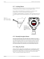
4.7.1 Latching Alarms
When the FUNCTION DIP switches are set up for latching operation, the WARN and
ALARM annunciators must be manually reset/acknowledged as follows:
Remote RESET/ACKNOWLEDGE is accomplished by a momentary-action
pushbutton that is wired to Terminal Block TB4 per Figure 4-6.
Local RESET/ACKNOWLEDGE is accomplished, without opening the enclosure, by
moving the magnet tool back-and-forth along the cover’s ridge as shown in Figure
4-7.
Figure 4-7.
Non-Intrusive Relay
Reset / Acknowledge
Delay /
Over-range
Fault / Keypad
‘CAL’ Mode
Unity
Span
Zero
CAL
RELAY RESET
AND ACKNOWLEDGE
MOVE MAGNET TOOL
BACK-AND-FORTH WITHIN
THIS AREA AT THE COVER’S
RIDGE
4.7.2 Normally Energized Alarms
The FUNCTION DIP switches allow the WARN and ALARM relays to operate
normally energized when the transmitter is powered, but when no alarm condition
exists. When an alarm condition occurs, the relays then de-energize. The advantage of this configuration is that a loss-of-power condition creates the same relay
outputs as an alarm condition. Note, however, that the annunciators must be
powered by a backup power source if they are to activate during a power outage.
Also note that the FAIL relay should always be operated normally energized.
4.7.3 Relay Trip Points
Alarm 1 and Alarm 2 trip points are controlled by two 16-position rotary switches.
See Figure 4-6 for a definition of the switch positions. Note that both alarm setpoints incorporate approximately 1.5% hysteresis. In other words, the signal must
drop about 1.5% below the trip level to reset the alarm. This prevents alarm
“chatter” when the input signal equals the trip level.
Page 28
Scot t H ea lt h & Sa fet y
In st r u ct ion 9550-9142 Rev. 5
4800A NIC II LE L Tr a n sm it t er
Op e r a t ion
4.8 Modbus RS-485 Board Wiring and Setup
ASSY 10-0128
Figure 4-8.
Modbus RS-485 Board
R11
R10
U3
Q1
C7
S1
RN2
P1
C1
TX & RX ARE TRANSMIT / RECEIVE
LED’s USEFUL IN TROUBLESHOOTING TX
Y1
RX
TB1 IS FOR RS-485 CABLE CONNECTION.
IN 2-WIRE MODE 1 & 2 MAY BE INCOMING CABLE AND 4 & 5 EXITING
CABLE
2wire
U2
C4
JP1-HOLD = HOLDS MODBUS
VALUE AT -15% DURING CALIBRATIONS
R1
R2
C2
C8
R9
HOLD
TRACK
JP1
JP1-TRACK = MODBUS VALUE TRACKS
READING DURING CALIBRATIONS
U1
4wire
JP2 DETERMINES 2-WIRE OR
4-WIRE RS-485 OPERATION.
JUMPERS SHOWN IN 2-WIRE
CONFIGURATION.
RIBBON CABLE TO
I/O BOARD
U4
U5
U6
U7
R6
R8
RXA RXB
TB1
1
RS-485 TERMINATING RESISTOR
(REMOVE EXCEPT FOR UNIT AT
“END OF LINE”)
2
SHLD.
RN1
8-BIT RTU ADDRESS
DIP SW. 1 = LSB
DIP SW. 8 = MSB
T/
T/
RXA RXB
3
4
5
R7
R12
R13
R14
AW 0010-1092
REV. A
C6
SW1
The optional Modbus RS-485 Serial Interface board (Figure 4-8) allows up to 128
transmitters to communicate to a Modbus master device on a single cable. Modbus
is the protocol, or language used by the transmitter to communicate with other
devices. The transmitter is a Modbus slave that requires a Modbus master to
interrogate it and retrieve information made available in specific register locations.
Modbus master devices are typically PLCs or PCs running HMI or GUI software
equipped with a Modbus driver.
4.8.1 RTU Address
The 8 position switch, SW1, allows a different RTU address to be assigned to each
transmitter. The 8 switches represent an 8 bit binary number with 1 = LSB and
8 = MSB. For example, OFF, ON, ON, OFF, ON, OFF, OFF, OFF = 0110 1000 =
RTU address 104. A unique RTU address must be assigned to each transmitter
communicating on the same RS-485 port.
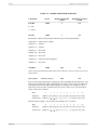
4.8.2 Modbus Data Registers and Function Codes
Table 4-2 identifies the transmitter’s Modbus register locations and function codes
that are available.
In st r u ct ion 9550-9142 Rev. 5
Scot t H ea lt h & Sa fet y
Page 29
Wir in g
4800A NIC II LE L Tr a n sm it t er
TABLE 4-2. MODBUS REGISTER SUMMARY
VARIABLE
Fail Bit
ALIAS
READ FUNCTION
CODE
WRITE FUNCTION
CODE
12000
2
NA
12008
2
NA
0 = OK
1 = Fault
Alarms
Returned as 8 discrete bits packed in the low byte of the response data.
12008:bit 0 = Fault (tracks 12000)
12008:bit 1 = Alarm1
12008:bit 2 = Alarm2
12008:bit 3 = Not Used
12008:bit 4 = Not Used
12008:bit 5 = Not Used
12008:bit 6 = Alarm2 Acknowledgeable
12008:bit 7 = Not Used
A2D Raw
33000
3&4
NA
10 bit value representing the A2D value of 0 to 1023 for -20 to 103 %FS (197=0% &
1003=100%).
A2D AS CII
31010 (6 by te s )
3 &4
NA
6 bytes of data representing the scaled span value including the decimal point. The
first 5 bytes contain the value with the last byte being a space. They are arranged
with the first byte as the MSD with leading zero spacing. For example, with a
span value of 1234 with 1 decimal point, the correct value of 123.4 is returned for
100% of full scale as follows:
Byte
Response
0
1
2
3
4
5
6
7
8
9
10
[address] [04] [06] [31] [32] [33] [2E] [34] [20] [Crcl] [Crch]
ASCII Char [address] [ ] [ ] [1 ] [2]
[3]
[.]
[4] [sp] [Crcl] [Crch]
With the same settings a 50% of full scale reading of 617 would be:
Byte
Response
0
1
2
3
4
6
7
8
9
10
[address] [04] [06] [20] [36] [31] [2E] [37] [20] [Crcl] [Crch]
ASCII Char [address] [ ] [ ] [sp] [6]
Page 30
5
Scot t H ea lt h & Sa fet y
[1]
[.]
[7] [sp] [Crcl] [Crch]
In st r u ct ion 9550-9142 Rev. 5
4800A NIC II LE L Tr a n sm it t er
Wir in g
TABLE 4-2. MODBUS REGISTER SUMMARY (Cont.)
VARI ABLE
EUNITS
ALI AS
READ FUNCTI ON
CODE
WRI TE FUNCTI ON
CODE
40319-40324
3
6
6 ASCII characters assigned to the engineering units read as bytes.
Measurement
Name
4 0 3 2 5 -4 0 3 4 0
3
6
16 ASCII characters assigned to the unit identifier read as bytes.
Span
40343
3
6
An integer from 1 to 9999 used to scale the A2D ASCII value.
Alm1Setpoint
40345
3
6
Alm2Setpoint
40347
3
6
Integer compared to the A2D Raw value to determine alarm 1 or 2 status.
The 0 to 100% set point must be scaled from 197 to 1003. This is done by
using (Alarm% * 806) + Offset .
Example: A 40% set point would be computed as (0.4 * 806) + 197
D.P.Position
40349
3
6
Determines how many decimal positions return with the A2D ASCII value. Valid
range is 0 to 3.
Alm1Trip
40351
3
6
Alm2Trip
40359
3
6
Set to 255 alarms on high, set to 0 alarm on low.
Alm1Latch
40353
3
6
Alm2Latch
40355
3
6
Set to 0 causes alarm 1 or 2 to auto reset, set to 255 causes alarms 1 or 2 to latch.
AlmZoneWord
40357
3
6
16 bit value which may be used as a zone alarm mask for the master.
AlarmReset
2000
NA
5
Setting to 255 causes any latched or acknowledgeable alarms to reset.
InitRtu
2010
NA
5
Setting to 255 causes a re-start which applies updated configuration variables.
In st r u ct ion 9550-9142 Rev. 5
Scot t H ea lt h & Sa fet y
Page 31
Wir in g
4800A NIC II LE L Tr a n sm it t er
4.8.3 MODBUS Configuration Software
All of the register values described in Section 4.8.2 must be configured via the
serial port. This is a one time only requirement unless changes within the application necessitate adjustments after the initial installation. This function is
usually built into the Modbus master.
4.8.4 RS-485 Wiring
The RS-485 electrical standard allows cable lengths up to 4000 feet between
Modbus master and slave. Both 4-wire full duplex and 2-wire half duplex connections are supported. Place a jumper on JP2 to correspond to the number of wires
being used. See Figure 4-9.
4.8.5 R4/R7 End-of-Line Terminating Resistor
Note:
Current boards (Rev. A or later) only have R7 resistor, see Figures 4-8 and 4-9.
Older boards (Rev. 0) have R4 and R7 resistors, see Figure 4-9.
R4/R7 are socketed, plug-in resistor positions for a 120 ohm End-of-Line terminating resistor. All units are supplied with one 120 ohm resistor installed. Remove
the resistor from all transmitters, except for the transmitter at the end of the
serial communications Data Highway. The unit furthest from the Host Computer
or other master communications device such as a PLC or system controller MUST
have one 120 ohm resistor installed. Position R4 is used with a 2-wire, half-duples
data communications highway, while Position R7 is used with a 4-wire, full-duples
highway. See applicable Figures 4-8 and 4-9.
Note: On very short runs, (e.g. less than 20 feet) no resistor is typically required.
Page 32
Scot t H ea lt h & Sa fet y
In st r u ct ion 9550-9142 Rev. 5
4800A NIC II LE L Tr a n sm it t er
Figure 4-9.
Typical RS-485 Wiring
RS-485 4 WIRE NETWORK
T/RXB
RS232 TO
COMPUTER
T/RXA
RS232/485
4 WIRE
CONVERTER
ADDRESS 4 THRU n
RXB
RXA
SET JP2
TO 4 WIRE
(SEE DETAILS
BELOW)
SET JP2
TO 4 WIRE
(SEE DETAILS
BELOW)
4w
SET JP2
TO 4 WIRE
(SEE DETAILS
BELOW)
4w
TB1
2w
4w
TB1
2w
1 2 345
MODBUS
OPTION BOARD
ADDRESS 1
TB1
2w
1 2 345
1 2 3 45
MODBUS
OPTION BOARD
ADDRESS 2
MODBUS
OPTION BOARD
ADDRESS 3
IMPORTANT!
These drawings reference the National Semiconductor standard specification
in regard to the polarity of terminals A & B. Some converter manufacturers,
e.g. B&B, have chosen to reverse this polarity. Please note that reversing
this polarity will cause the transmitter to not send the digital stream in a
correct fashion and therefore the unit will not communicate properly. Note that
A is the positive or high side and B is the negative or low side of the input.
RS232 TO
COMPUTER
RS-485 2 WIRE NETWORK
T/RXB
RS232/485
2 WIRE
CONVERTER
ADDRESS 4 THRU n
T/RXA
SET JP2
TO 2 WIRE
(SEE DETAILS
BELOW)
SET JP2
TO 2 WIRE
(SEE DETAILS
BELOW)
4w
SET JP2
TO 2 WIRE
(SEE DETAILS
BELOW)
4w
TB1
2w
4w
TB1
2w
1 2 345
MODBUS
OPTION BOARD
ADDRESS 1
TB1
2w
1 2 345
1 2 3 45
MODBUS
OPTION BOARD
ADDRESS 2
MODBUS
OPTION BOARD
ADDRESS 3
Rev. 0 & Rev. A Version Boards
(Boards shown are jumpered for 2 wire operation.
Move jumper JP2 to 4W for 4 wire operation.)
P1
P1
JP3
2W
HOLD
4W
TRK
HOLD
JP1
TRK
JP1
JP2
4W
JP2
8765432 1
TB1
ON
SW1
1
2
3
4
2 WIRE
RS-485
TB1-1 = RXA
TB1-2 = RXB
TB1-3 = SHLD.
TB1-4 = T/RXA
TB1-5 = T/RXB
MODBUS RS-485 BOARD
(AW 0010-1092 REV. 0)
In st r u ct ion 9550-9142 Rev. 5
OFF
2W
TERMINIAL BLOCK (TB1) TERMINATIONS
5
R7
R4
87654321
TB1
OFF
ON
SW1
1
2
3
4
5
R7
MODBUS RS-485 BOARD
(AW 0010-1092 REV. A)
Scot t H ea lt h & Sa fet y
Page 33
Wir in g
4800A NIC II LE L Tr a n sm it t er
Notes
Page 34
Scot t H ea lt h & Sa fet y
In st r u ct ion 9550-9142 Rev. 5
4800A NIC II LE L Tr a n sm it t er
Ca libr a t ion
5 Calibration
WARNING!
B efore perform in g an y calibration proced u res th at requ ire th e
rem oval of th e tran sm itter cover, be su re to d eclassify th e area
to n on -h azard ou s before open in g th e tran sm itter or an y oth er
electrical en closu res.
5.1 Calibration Intervals
• Calibrate after initial installation
• Calibrate after replacing the transmitter, the sensor, detector or any
circuit assemblies
• Calibration frequency is to be determined by the user however as a general rule
check calibration once a week for the first month of operation; then monthly or
as experience dictates thereafter.
5.2 Preparing for Calibration
Calibrate the transmitter and detector preferably on the gas that it will be monitoring. If more than one gas or vapor will be monitored, calibrate the instrument on
the gas /solvent vapor that requires the highest gain setting on the transmitter.
Contact Scott Health & Safety for additional information if necessary. Refer to
Appendix "A" for additional calibration details and a chart with recommended
calibration gas to be used for most common combustible vapors.
Equipment required for calibration:
• Digital Volt Meter (DVM) with a minimum accuracy of 0.5% and a 2.00 Vdc
range
• Small flat blade screwdriver
• Calibration Kit – See Appendix “A” and Section 8.5 Accessories
• Calibration Cup:
- 23-4098 for Diffusion 6 Volt detector ( "Gold Bell" configuration)
- 3470-9500 for Diffusion 6 Volt detector with Duct Adapter
N ot e: 5.5 Vol t d et ec t or s d o n ot r eq u i r e a c a l i b r a t i on c u p (S c ot t
st a i n l ess st eel c on fi g u r a t i on )
• Sensor Adapter Board 23-4027: Only required for a 6 Volt detector mounted more
than 18" away from the transmitter.
• Zero Gas Cylinder: See Section 8.5 Accessories
• Combustible gas cylinder(s): See Appendix “A” and Section 8.5 Accessories
In st r u ct ion 9550-9142 Rev. 5
Scot t H ea lt h & Sa fet y
Page 35
Ca libr a t ion
4800A NIC II LE L Tr a n sm it t er
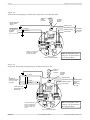
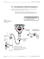
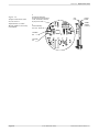
5.3 Assembling the Calibration Equipment
Assemble the calibration fixture as shown in Figure 5-1, using the appropriate
calibration kits that is listed in Section 8.5 Accessories.
Note: 6 Volt detectors require a nominal gas flow of 1 liter per
minute. The 5.5 Volt detectors require a nominal gas flow of 2 liters
per minute. Be sure that the proper gas bottle regulator is used.
FOR CALIBRATING THE SCOTT 5.5V
CATALYTIC BEAD SENSOR, REFER
TO APPENDIX C, FIGURE C-5
Figure 5-1.
Calibration Fixture Showing 6V "Gold Bell"
Catalytic Bead
Delay /
Over-range
‘CAL’ Mode
Unity
Span
Fault / Keypad
0–100% LEL
COMBUSTIBLES
Zero
CALIBRATION CUP
3470-9500 FOR
DUCT ADAPTER
CAL
DETECTOR FROM DUCT
ADAPTER REMOVED FROM
ITS MOUNTING PLATE
HOSE *
REGULATOR
1 LPM For 103 Liter
Tanks *
REGULATOR
For 17 Liter
Tanks *
CALIBRATION CUP
23-4098 FOR
DIFFUSION
DETECTOR
CALIBRATION-GAS CYLINDER
(See Section 8.2 Accessories for Part Number)
* Regulator and Hose are part of 17 Liter Calibration
Kit 23-7260, or 103 Liter Calibration Kits
51-2938 and 51-7339.
Page 36
Scot t H ea lt h & Sa fet y
In st r u ct ion 9550-9142 Rev. 5
4800A NIC II LE L Tr a n sm it t er
Ca libr a t ion
5.4 Initial Start-Up
Perform these procedures after installing a new transmitter, or after replacing the
transmitter’s Input/Output printed circuit board or whenever a sensor / detector is
replaced. For routine calibration, skip to Section 5.6 Routine Calibration.
WARNING!
Declassify th e area to n on -h azard ou s before open in g th e tran sm itter h ou sin g or an y oth er electrical en closu res.
Remove the cover from the transmitter enclosure. To access the adjustment
potentiometers and terminals on the Input / Output board, remove the front panel
by loosening the two (2) thumbscrews located on the panel. Pull the front LCD
panel away from the enclosure. The LCD panel is connected to the Input / Output
board with a ribbon cable that has sufficient length so that the panel can be placed
to the side for access. Do not disconnect the cable at either end.
After all power and signal connections have been made and checked, apply power to
the transmitter. The current loop output will be held for approximately one (1)
minute at 4 mA as indicated by the flashing delay arrow on the LCD. This delay
time upon initial power up is to allow the sensor time to stabilize, thus reducing
the possibility of an erroneous alarm condition. Allow a new sensor to stabilize for
one (1) hour before proceeding.
5.4.1
Input Voltage Check
Measure the inout voltage with a DVM as shown in Figure 5-2 across TB2 terminals PWR and GND and verify that it is between 18 and 30 Vdc (or 10 to 18 Vdc if
a jumper has been installed in J04 on the Inout / Output board).
If the measured voltage is not correct, check the power supply. Also check that the
powerwiring wire length and wire size is adequate as described in Section 3.
GND (COMMON)
R
C
A
TB1
OUT SIG
SPARE
JUMPERS
PWR
Figure 5-2. Input Voltage
M easu rem en t Poin ts
TB2 JP1
12 34
VOLTS
BAL
J04
+
–
INPUT / OUTPUT BOARD
In st r u ct ion 9550-9142 Rev. 5
Scot t H ea lt h & Sa fet y
Page 37
Ca libr a t ion
4800A NIC II LE L Tr a n sm it t er
5.4.2
Sensor Voltage Adjustment
The sensor voltage will need to be adjusted to either 6.0 Vdc or 5.50 Vdc depending
on which sensor / detector is installed. The voltage must be adjusted as measured
at the detector location. To check and adjust this voltage, use one of the following
procedures:
D e te c to rs - 6.0 Vd c ("Go ld B e ll" c o n fig u ra tio n )
-
Refer to Figure 5-3
-
If the detector head is attached to the transmitter or located no more than 18
inches away, connect a DVM to TB1-R and TB1-A and adjust the Volts potentiometer for a DVM indication of 6.00 +/- 0.05 Vdc.
-
If the detector head is located more than 18 inches from the transmitter,
disassemble the detector head and install a Sensor Adapter Board 23-4027
between the sensor and the detector socket.
-
Attach the DVM to the adapter board terminals “A” and “R” and adjust the
Volts potentiometer for a DVM indication of 6.00 +/- 0.05 Vdc.
-
Remove the Adapter Board and reassemble the detector head
DETECTOR
BODY
R
C
–
SENSOR
ADAPTER
BOARD
23-4027
COMBUSTILBES
SENSOR
A
TB1
OUT SIG
SPARE
JUMPERS
PWR
GND (COMMON)
+
Figure 5-3.
S en sor V oltage
M easu rem en t an d
Adjustment
TB2 JP1
1234
VOLTS
DVM Connection To
Sensor Adapter Board
BAL
J04
Z
R (+)
R
SENSOR
VOLTAGE
ADJUST
C A
INPUT / OUTPUT BOARD
Page 38
Scot t H ea lt h & Sa fet y
A (–)
In st r u ct ion 9550-9142 Rev. 5
4800A NIC II LE L Tr a n sm it t er
Detectors - 5.50 Vdc (Scott stainless steel configuration)
-
Refer to Figure 5-4.
-
Remove the detector outer guard. Measure the voltage across the test points as
indicated and adjust the Volts potentiometer for a DVM indication of 5.50 Vdc.
-
Replace the detector outer guard.
Figure 5-4.
S COT T 5.5V Detector T est Poin ts
SENSOR DRIVE VOLTAGE
5.50 ±.1VDC
TEST POINT
"NEGATIVE"
TEST POINT
"POSITIVE"
SENSOR
TEST POINT SIGNAL USED TO MEASURE BRIDGE VOLTAGE
(TROUBLE SHOOTING PURPOSES)
CALIBRATION PORT
(1/8" NPT)
In st r u ct ion 9550-9142 Rev. 5
Scot t H ea lt h & Sa fet y
Page 39
Ca libr a t ion
4800A NIC II LE L Tr a n sm it t er
5.4.3
Monitoring the VOUT Test Point
The V OUT test point on the Input / Output board may be monitored during the
remainder of this section to verify correct initial setup. Connect the DVM to TB2
GND and V OUT as shown in Figure 5-5.
V OUT has a total voltage swing of 1.6 volts, with an active range of 0.4 to 2.0
volts corresponding to 0 to 100 % LEL. The Input / Output board may be considered properly configured when V OUT is at or slightly above the desired value. A V
OUT voltage that is below the expected value may result in a shortened sensor life.
5.4.4
Balance Adjustment
The balance adjustment matches the resistance of a sensor to the transmitters
input bridge circuit. This adjustment is required whenever a new sensor is installed. Adjust the BAL potentiometer as follows but only after the new sensor has
stabilized for (1) hour minimum:
1. Connect a DMM to the I/O board as shown in Figure 5-5.
2. With the detector exposed to combustible gas-free air, adjust the
BAL potentiometer until the VOUT test point measures 0.4 Vdc.
This is an approximate adjustment. Precision zero adjustment is made using the
magnetic zero controls. The Zero Up and Down arrow keys have an adjustment
range of +/- 15% of full scale that the sensor would have to drift beyond before the
BAL potentiometer would require further adjustment.
Use of combustible gas free air is required for installation areas that may contain
combustible or flammable vapors.
Figure 5-5.
Test Point VOUT, Balance
Adjustment, and JP1 Gain
Setting
+
VOUT
TRANSMITTER
VOLTAGE OUT
TEST POINT
GND (COMMON)
R
C
A
TB1
OUT SIG
SPARE
JUMPERS
PWR
–
TB2 JP1
12 34
VOLTS
BAL
J04
JP1
SENSOR
GAIN
SENSOR
BALANCE
ADJUST
INPUT / OUTPUT BOARD
Page 40
Scot t H ea lt h & Sa fet y
In st r u ct ion 9550-9142 Rev. 5
4800A NIC II LE L Tr a n sm it t er
Ca libr a t ion
5.4.5 Initial Fixed Gain (JP1) Setting
The transmitter has four fixed gain settings that select the range of sensitivity of
the sensor. The gain settings are selectable via the location of jumper(s) on JP1
located on the I/O board (Figure 5-5). Each jumper position provides a different
amount of sensor amplification. Different gain settings are required for various
combustible gas and solvent vapors to be detected. The gain values for JP1 are as
follows:
Jumper in Position 1 = Gain of 51
Jumper in Position 2 = Gain of 26
Jumper in Position 3 = Gain of 12.5
Jumper in Position 4 = Gain 7
No Jumper = Gain of 1
Note: Multiple jumpers are
additive in relation to gain.
For example, jumpers can be
placed in positions 3 and 4 to
provide a gain of 19.5.
To determine the proper gain jumper position, either the gas to be detected must be
applied to the sensor or the surrogate gas to be used for calibration must be applied. The jumper location is determined while measuring the voltage on the VOUT
test point or by observing the LCD display when the UNITY mode is selected.
Important: JP1 must be configured only with a new sensor.
Configuring JP1 using a sensor that has been is use for any period
of time may cause inaccurate gas readings.
Note: JP1 is located to set the course span value by setting the
gain of the sensor's bridge circuit. JP1 is only a coarse setting.The
Span Up and Down arrow keys have an adjustment range equal to a
minimum gain of 0.5 to a maximum gain of 2 (For example, when
the gain jumper JP1 is located in position 4, a course gain of 7 is
set. The arrow keys can reduce the gain to 3.5 or raise it to 14.)
VOUT Test Point Method:
The VOUT test point has a total voltage swing of 1.6 volts between 0.4 and 2.0 Vdc.
This voltage swing is equivalent to 0 - 100% LEL. Therefore, a voltage of 1.2 Vdc
will correspond to 50 % LEL. Use Equation 5-1, Table 5-1 and Appendix "A" to
determine the span voltage that is to be indicated on the VOUT test point for a
given calibration. The following examples show how to properly use the information
contained in these sections.
Example 1: If Methane in air is the gas to be monitored, apply an appropriate
calibration gas to the detector (preferably use 2.5% Methane which is 50% LEL).
The JP1 jumper is to be configured so that the voltage measured at VOUT corresponds to the gas concentration applied. If 2.5% Methane in air is used (50% LEL),
position JP1 so that the voltage at VOUT is approximately 1.2 Vdc or slightly
higher.
When finished, remove gas from sensor and go to Section 5.4.6
In st r u ct ion 9550-9142 Rev. 5
Scot t H ea lt h & Sa fet y
Page 41
Ca libr a t ion
4800A NIC II LE L Tr a n sm it t er
Note: Example 2 assumes 6V "Gold Bell" catalytic bead sensor
Example 2: If Acetylene in air is the gas to be monitored, Propane in air will be used
as a surrogate gas as detailed in Appendix "A". The voltage to be measured at VOUT is
based on the K-Factor of Acetylene. Using the procedure detailed in Appendix "A", it is
determined that 42.9% Propane in air is equivalent to 60% LEL Acetylene. The VOUT
that corresponds to 60% LEL is 1.36 Vdc (see Table 5-1). Therefore, by applying 42.9%
LEL Propane in air (0.94 % Propane), position JP1 so that the voltage at VOUT is
approximately 1.36 Vdc or slightly higher.
When finished, remove gas from sensor and go to Section 5.4.6
Equ ation 5-1
VOUT = [1.6 x (LEL of calibration gas / 100)] + 0.40
Example:
VOUT for a 25% LEL calibration gas cylinder is:
VOUT = [1.6 x (25 / 100)] + 0.40 = 0.80 Vdc
TAB LE 5-1.
CALIB RATION GAS v s . VOU T
Calibration Gas
(%LEL)
VOUT
(VDC)
10
20
30
40
50
60
70
80
90
0.56
0.72
0.80
1.04
1.20
1.36
1.52
1.68
1.84
LCD Display Method using Unity Mode:
This method of configuring JP1 for the proper gain setting uses the LCD to display
the sensor output. The transmitter must first be placed into its Unity Gain Mode
as follows:
1. With power off to the transmitter, hold a magnet over the UNITY symbol on
the LCD module.
2. Turn on the power to the transmitter. The LCD will display "cb" a few seconds
after the power is turned on. Remove the magnet from the display.
3. The LCD will show a value with both the flashing arrow and steady arrow on
for (1) minute.
4. This will set the gain to unity (no gain), the meter span to 100 and the End of
Service Life value to 1.9.
Page 42
Scot t H ea lt h & Sa fet y
In st r u ct ion 9550-9142 Rev. 5
4800A NIC II LE L Tr a n sm it t er
Ca libr a t ion
The Unity feature has now been activated so that the LCD display can be used to
position JP1.
Important: W h en ever th e Un ity featu re is activated , th e
transmitter must be recalibrated. All previous calibration information
w ill be erased w h en th e Un ity featu re is accessed .
Use Equation 5-1, Table 5-1 and Appendix "A" to determine the level that is to be
displayed on the LCD for a given calibration. The following examples show how to
properly use the information contained in these sections.
Example 1: If Methane in air is the gas to be monitored, apply an appropriate
calibration gas to the detector (preferably use 2.5% Methane which is 50% LEL). The
JP1 jumper is to be configured so that the LCD display corresponds to the gas concentration applied. If 2.5% Methane in air is used (50% LEL), position JP1 so that the
display on the LCD is approximately 50 or slightly higher.
When finished, remove gas from sensor and go to Section 5.4.6
Note: Example 2 assumes 6V "Gold Bell" catalytic bead sensor
Example 2: If Acetylene in air is the gas to be monitored, Propane in air will be used
as a surrogate gas as detailed in Appendix "A". The LCD display is based on the KFactor of Acetylene. Using the procedure detailed in Appendix "A", it is determined
that 42.9% Propane in air is equivalent to 60% LEL Acetylene. Therefore, by applying
42.9% LEL Propane in air (0.94 % Propane) position JP1 so that the display on the
LCD shows approximately 60 or slightly higher.
When finished, remove gas from sensor and go to Section 5.4.6
5.4.6
Completing Initial Start-Up
After completing the initial start-up procedures, reinstall the front panel assembly
by aligning the (2) thumbscrews with their mating standoffs and tightening firmly
by hand. Replace the housing cover and tighten its locking screw.
5.5 End of Service Life
The model 4888A NIC II Transmitter has a standard feature whereby the sensor
gain level can be displayed after calibration and compared to a user adjusted level
for the purpose of determining the remaining service life of the sensor.
Catalytic combustible sensors inherently lose output signal strength as they age.
Knowing the signal strength of a new sensor as defined by the gain applied during
calibration when it is first installed allows a user to track its signal deterioration
over time.
In st r u ct ion 9550-9142 Rev. 5
Scot t H ea lt h & Sa fet y
Page 43
Ca libr a t ion
4800A NIC II LE L Tr a n sm it t er
A high gain level alert can be activated by the 4888A as a means of automatic
notification following a successful calibration that a particular sensor is nearing its
end of service life. This enables a user to plan sensor replacement during scheduled
maintenance time while the sensor is still operational rather than after a sensor is
found to be beyond its service life which is typically not known until a calibration is
attempted unsuccessfully.
The gain value will display from 0.50 to 2.00. (0.50 representing a low gain and
2.00 representing a high gain value). This value represents the amount of gain
applied to the sensor output signal to calibrate it. The initial gain applied to a new
sensor during the initial calibration will be dependent on the gas / solvent vapor
that the detector is being calibrated for as well as the position of JP1. It is normal
for new sensors calibrated on the same cal gas to have initial gain settings vary by
as much as 20 percent. Sensors will also lose output signal strength at varying
levels due to many factors regarding the application and operating environment.
Calibration frequency and how often / how much gas is detected will also affect the
loss of sensitivity of a given detector.
5.5.1
Display Gain Setting
In normal operation, hold a magnet over the SPAN DOWN arrow key. The gain
will display as a number between 0.50 and 2.00 with the delay arrow flashing. The
gain will display so long as the magnet remains over the SPAN DOWN arrow key.
Remove the magnet and the display will go back to normal operation.
This value represents the gain applied to the sensor output at the time it was last
calibrated. Each time the sensor is calibrated the gain setting may change to a
higher value as additional gain is applied to the sensor output to compensate for the
loss of sensitivity that is inherent in catalytic bead sensors.
5.5.2
Set End of Service Life Indicator
The 4888A NIC II will display "ESL" every ten seconds after a calibration results in
the gain applied to the sensor output exceeding the trip point that has been set. The
gain range is 0.50 to 2.00 as described in section 5.4.5. The factory trip point is
adjusted at 1.90 and is adjustable by the user as follows:
1
2
3
4
Page 44
In normal operation, hold a magnet over the UNITY key for approximately 5
seconds until a value is displayed with the delay arrow flashing.
The value displayed will be the Compared Gain Value and is adjustable from
0.50 to 2.01.
Use the SPAN UP/DOWN arrow keys to adjust this value. Setting the value
to 2.01 w ill d is a ble th e ES L fe a tu re .
After the desired value is displayed, hold the magnet over the UNITY key
momentarily to return to normal operation.
Scot t H ea lt h & Sa fet y
In st r u ct ion 9550-9142 Rev. 5
4800A NIC II LE L Tr a n sm it t er
Ca libr a t ion
5.6 Routine Calibration
(Non-Intrusive)
Routine calibration does not require the area to be declassified as non-hazardous
since all adjustments are done with the transmitter’s cover intact. Adjustments are
made through the housing’s transparent window using a magnet tool that is
supplied with the transmitter.
Routine calibration consists of first applying a zero gas to the sensor and adjusting
the magnetic Zero controls for a zero indication on the transmitter’s LCD display.
An appropriate span gas is then applied and the magnetic Span controls are
adjusted for the correct span value.
Note: W h ile in th e calibration m od e, th e tran sm itter’s ou tpu t is
h eld at 1.5 m A to preven t alarm s from bein g tripped by th e
span gas that will be applied later in the calibration procedure.
H ow ever, tran sm itters in tegrated in to CE 130 S ystem s w ill
cau se th e system 's FAIL relay to d rop ou t.
Zer o Ad ju st m en t
1. Attach a zero-gas cylinder to the regulator of the calibration fixture.
2. Place transmitter into its calibration mode by briefly holding the magnet tool over
the “CAL” dot on the front-cover plate. The transmitter responds by displaying a
left-hand arrow on the LCD display. See Figure 5-6.
The calibration mode is indicated by a steady arrow. It is important that this
arrow is not flashing during calibration, since a fast flash rate of 3–4 times per
second indicates a saturated A-D converter. If the arrow is flashing, ensure that
jumper JP1 on the Input/Output board is correctly installed per Section 5.4.5.
3. Open regulator on calibration fixture and allow zero gas to flow over sensor
until LCD readout stabilizes.
4. Zero readout by holding magnet tool over the appropriate Zero
the LCD display shows zero.
symbol until
5. Shut off regulator, and remove zero-gas cylinder.
S P AN Ad ju st m en t
6. Attach an appropriate span-gas cylinder to the calibration fixture’s regulator.
7. Open regulator and allow span gas to flow over sensor until the LCD
readout stabilizes.
8. Hold magnet tool over the appropriate Span
indication is observed on the LCD display.
In st r u ct ion 9550-9142 Rev. 5
Scot t H ea lt h & Sa fet y
symbol until the correct span
Page 45
Ca libr a t ion
4800A NIC II LE L Tr a n sm it t er
If a flashing left hand arrow appears on the LCD during calibration, the
calibration procedure should be halted since the analog voltage being applied
to th e A -D con verter is too h igh . E ith er th e span gas con cen tration is in correct, or the fixed gain jumper on the Input/Output board is set incorrectly
(refer to S ection 5.4.5).
9. Shut off regulator and remove calibration cup. Then before proceeding with
Step 10, wait until the transmitter’s LCD readout drops below the system’s
alarm trip-points; otherwise, alarms may sound when the transmitter is placed
back into its normal-mode of operation.
10. Exit the calibration mode by again briefly holding the magnet tool over the
front panel’s “CAL” dot. The left-hand arrow should now start slow flashing
and then turn off after a 1 minute delay.
If the calibration mode is not exited manually, it will automatically exit after
5 minutes of keypad inactivity.
11. Disassemble the calibration fixture.
Figure 5-6.
Front Panel Indicators and
Magnetic Adjustments (as
seen th rou gh th e Fron t
Cover Window)
FAULT / KEYPAD LED
(Lights under fault
conditions, and when
the magnet tool is held
over a magnetic keypad
control)
Steady State Arrow Indicates
the Calibration Mode
Slow Flashing Arrow Indicates
a Power-On or CAL Exit Delay
Flast Flashing Arrow Indicates
an Over-range Condition
Five rapid flashes indicate
entry into the Unity Gain
Mode
UNITY GAIN MODE
ENTER
Delay /
Over-range
Fault / Keypad
‘CAL’ Mode
Unity
Span
LCD DISPLAY
(Shows combustible
gas level in % LEL)
Zero
CAL
ZERO UP ADJ.
SPAN DOWN ADJ.
ZERO DOWN ADJ.
SPAN UP ADJ.
CALIBRATION MODE
ENTER / EXIT
RESET & ACKNOWLEDGE
ALARM MAGNETIC SWITCH
(Hold magnet tool near base of
housing cover at this location.
Refer to Section 4.7.1.)
Page 46
Scot t H ea lt h & Sa fet y
In st r u ct ion 9550-9142 Rev. 5
4800A NIC II LE L Tr a n sm it t er
5.7 4-20mA Simulate Mode:
During NORMAL MODE operation, holding the magnet over the DOWN ZERO
key for at least 10 seconds places the unit into a 4-20mA SOURCE MODE. The
LCD indicates directly in milliamps the actual value of the 4-20mA output and is
irregardless of gas on the sensor. The UP/DOWN SPAN keys are used to set this
value between 4mA and 20mA. This feature is provided to make it easier to test
display and alarm devices connected to the 4800A's 4-20mA output without exposing the sensor to test gas. 4-20mA SOURCE MODE exits back to NORMAL MODE
by touching the UNITY key or automatically after 5 minutes without operator
input.
In st r u ct ion 9550-9142 Rev. 5
Scot t H ea lt h & Sa fet y
Page 47
4800A NIC II LE L Tr a n sm it t er
6 Operation
6.1 ‘Normal Mode’ Operation
The 4888A-NIC II LEL Transmitter is in its ‘Normal Mode’ any time the LCD’s
left-hand arrow is not visible and the Fault/Keypad LED is not illuminated. At this
time the transmitter sends a standard 4–20 mA signal to the attached receiving
unit, where 4 mA corresponds to 0% LEL, and 20 mA corresponds to 100% LEL
full scale. If connected to a Scott Health & Safety Controller, the controller’s
readout begins to indicate the level of combustible gas surrounding the transmitter’s detector head.
In addition to the transmitter’s output signal, an LCD display, which is visible
through the housing window, shows the detected level of combustible gas in %LEL.
6.2 Fault Supervision
• With the transmitter operating in its ‘Normal Mode’ as described in Section 6.1,
a fault condition is signaled if the transmitter’s output drifts far enough negative to cause the output signal to drop to 2.4 mA (–10% of full scale).
Note: Du rin g ‘N orm al M od e’ operation , both th e tran sm itter’s
4–20 mA output and LCD readout do not track input values
below 0% of fu ll scale. T h is preven ts erron eou s an d m om en tary
negative noise signals from being transmitted and displayed,
but a –10% of full scale drift will still cause a fault indication to
occur.
• The transmitter is also equipped with fault-detection circuitry that detects when
the sensor’s catalytic beads open or short circuit. This fault condition will exist
until the sensor is replaced.
The transmitter signals either of the above fault conditions by lighting the front
panel Fault/Keypad LED, dropping out the ALARM 3 (FAIL) relay on the optional
relay board, and clamping the transmitter’s output signal at 0 mA.
Note: The ALARM 3 relay on the optional relay board should
always be configured as a FAIL alarm, causing this relay to deen ergize in th e even t of a fau lt con d ition .
If the transmitter is connected to a Scott Health & Safety Controller, the
transmitter’s 0 mA output signal will cause the controller’s FAIL indicator to light
and actuate its FAIL alarm circuit.
Page 48
Scot t H ea lt h & Sa fet y
In st r u ct ion 9550-9142 Rev. 5
4800A
Op
e r a tNIC
ion II LE L Tr a n sm it t er
6.3 Overrange
The A-D converter saturates at readings above 103% of full scale. At this point an
overrange condition is indicated by a fast flashing (3–4 times per minute) left-hand
arrow on the transmitter’s LCD display.
Note that if an overrange condition occurs during calibration, check if either the
span gas concentration is incorrect, or the fixed gain jumper on the Input/Output
board is set incorrectly (refer to Section 5.4.5).
The transmitter identifies an overrange condition to the receiving equipment by
locking its output signal at 20.5 mA until the overrange condition clears.
6.4 Sensor Flooding
WARNING!
Explosion hazard. The sensor could become damaged if the
d etector becom es flood ed or sam ples h igh com bu stible-gas
con cen tration s (over 100% L E L ) for lon g period s of tim e.
A lw ays recalibrate th e tran sm itter as per S ection “5.6 R ou tin e
Calibration (Non-Intrusive)” after sampling a high-gas concentration . If th e sen sor can n ot be calibrated , replace it per S ection
“7.2 R eplacin g th e S en sor”, an d th en recalibrate th e tran sm itt er.
If the atmosphere around the transmitter’s sensor becomes “flooded” with a high
concentration of combustible gas or vapor:
• The gas indication at the receiving unit and on the transmitter’s faceplate will
quickly jump above 60% LEL, and then rapidly fall to 0% LEL. This indicates
that a high, possibly explosive, concentration of combustible gas is surrounding
the detector. Even a concentration too rich to be explosive should be considered
dangerous.
The rapid increase of the gas reading was caused by the high concentration of
combustible gas combining with the air already inside the detector and being
oxid ized by th e sen sor. T h e n ow “flood ed ” sen sor can n o lon ger oxid ize th e gas
d u e to a lack of Oxygen , in tu rn , cau sin g th e gas read in g to retu rn to zero
even th ou gh com bu stible gas is still presen t at th e d etector.
• The WARN and ALARM annunciators, either activated by the optional relay
board or a Scott Health & Safety Controller, turn on and remain activated or
immediately turn off. Don’t attempt to reset alarms until the combustible gas or
vapor is cleared. Let qualified personnel reset alarms only after the area is
known to be free of combustibles.
If th e relays in th e alarm circu it are set u p for n on -latch in g operation , th en in
the case of sensor flooding as previously described, the annunciators will turn
on an d th en qu ick ly tu rn off even th ou gh com bu stible gas is still presen t at th e
d et ect or.
In st r u ct ion 9550-9142 Rev. 5
Scot t H ea lt h & Sa fet y
Page 49
4800A NIC II LE L TrOp
a nesm
r aitt ion
t er
• The transmitter won’t respond to new combustible gas concentrations at the
sensor until the atmosphere clears, and adequate Oxygen levels return.
For safety reasons, check calibration per Section 5.6 Routine Calibration (NonIntrusive) after the combustible gas or vapor flooding has cleared.
6.5 Delay Modes
6.5.1
Power Up Delay
The 4–20 mA output is held at 4 mA for 1 minute after power is first applied to the
transmitter. This delay is to allow the combustibles sensor time to stabilize and
reduce the possibility of causing an erroneous alarm condition within the gasdetection system.
6.5.2
‘CAL’ Mode Exit Delay
Span gas is typically the last gas applied during a routine calibration. If the CAL
mode is exited too quickly after removing span gas from the sensor, the reading
may still correspond to the span gas value and trip alarms. For this reason, the
transmitter’s 4–20 mA output is held at 4 mA for 1 minute after exiting the CAL
mode.
6.5.3
Automatic ‘CAL’ Mode Exit Timer
The transmitter’s 4–20 mA output is held at 1.5 mA during calibration. This alerts
any loop-monitoring devices that a special condition is present. Since it is possible
for an operator to forget to return the transmitter to its normal operating mode, the
transmitter’s microprocessor monitors the magnetic keypad while in the CAL
mode, and if no key stroke is made during a 5 minute interval the CAL mode is
automatically exited.
6.5.4
Aborting the Delay Modes
Troubleshooting or other testing procedures may be easier to perform without the
power-up and CAL-mode-exit delays active. These delays can therefore be temporarily turned off by first removing power; holding the magnet tool over the Zero
control; and then reapplying power. Note that the transmitter must not be in a
fault condition when power is reapplied.
Any subsequent power-up without holding the magnet tool over the Zero
reactivates both delay periods.
Page 50
Scot t H ea lt h & Sa fet y
control
In st r u ct ion 9550-9142 Rev. 5
4800A
Op
e r a tNIC
ion II LE L Tr a n sm it t er
6.6 Calibration Values Back-Up Power
An E2 PROM non-volatile memory device provides unlimited periods of continuous
storage of calibration values during power interruptions.
In st r u ct ion 9550-9142 Rev. 5
Scot t H ea lt h & Sa fet y
Page 51
4800A NIC II LE LMa
Trin
a nt sm
en aitnt ce
er
7 Maintenance
WARNING!
B efore perform in g an y m ain ten an ce proced u res th at requ ire
th e tran sm itter h ou sin g, d etector h ead , or an y oth er electrical
en closu re to be open ed , be su re to d eclassify th e area to n on hazardous.
It is advisable that spare transmitter circuit boards and sensors be on hand to
facilitate maintenance. The following sections describe how to:
•
•
•
•
Perform routine maintenance
Replace the sensor
Replace a transmitter circuit board
Readjust the LCD’s electrical SPAN (R19) and ZERO (R20) readings
7.1 Routine Maintenance
Routine maintenance consists of simply calibrating the transmitter as described in
Section 5.6 Routine Calibration (Non-Intrusive) on a periodic basis.
Check calibration of the transmitter once a week for the first month of operation;
monthly, or as experience dictates thereafter.
7.2 Replacing the Combustibles Sensor
Remove power from the transmitter. Then disassemble the detector head and
replace the sensor as shown in either Figure 7-1, 7-2, or 7-3.
After replacing the sensor, perform the procedures in Sections 5.4.2 Sensor Voltage
Check, 5.4.4 Balance Adjustment, 5.5 Checking Sensor Output Signal Strength,
and 5.6 Routine Calibration.
Figure 7-1.
S en sor R eplacem en t,
6V "Gold Bell" Diffusion
Head Assembly
Note: See Appendix C for
5.5V Scott Stainless Steel
Detector, view Figure C-6
6V "GOLD BELL" CONFIGURATION
Page 52
Scot t H ea lt h & Sa fet y
In st r u ct ion 9550-9142 Rev. 5
4800A
Ma
in t en
NIC
a n ce
II LE L Tr a n sm it t er
Figure 7-2.
S en sor R eplacem en t,
6V "Gold Bell"
Flow Cell Assembly
In st r u ct ion 9550-9142 Rev. 5
Scot t H ea lt h & Sa fet y
Page 53
4800A NIC II LE LMa
Trin
a nt sm
en aitnt ce
er
Figure 7-3.
S en sor R eplacem en t,
6V "Gold Bell" Duct
Adapter Assembly
Page 54
Scot t H ea lt h & Sa fet y
In st r u ct ion 9550-9142 Rev. 5
4800A
Ma
in t en
NIC
a n ce
II LE L Tr a n sm it t er
7.3 Transmitter Circuit Board Replacement
Material Required:
•
•
•
•
•
No. 1 Phillips-head screwdriver
Small flat blade screwdriver
7
/64" socket-head wrench
Method of tagging wires
Replacement boards as needed:
- Front Panel/CPU Board Assembly
- Input/Output Board
- Relay Board, Modbus RS-485 Board, or Isolated 4–20 mA Board
Procedure:
1. Disarm any annunciators; then switch off power to the transmitter.
2. Loosen socket-head screw on housing cover; then unscrew and remove cover.
3. Referring to Figure 8-1, disassemble the transmitter as necessary to remove
the circuit board being replaced. If the board has external wires connected to its
terminal block(s), be sure to first tag the wires before removing them.
4. Install the new circuit board. Then, if necessary, reconnect any wires that were
removed in Step 3.
If the Input/Output board was replaced, also be sure jumpers J04 and JP1 are
placed correctly. Refer to Sections 4.6.1 and 5.4.5 for information on jumper
placement. In addition, the board’s VOLTS and BAL potentiometers will need
to be adjusted per Sections 5.4.2 and 5.4.4.
If the Relay board was replaced, also be sure the ALARM 1 and ALARM 2
rotary switches and the FUNCTION DIP switch are set correctly. Refer to
Section 4.7 for information on switch positions.
If the Modbus RS-485 board was replaced, also be sure the DIP switches and
jumpers are set correctly. Refer to Section 4.8 for information on switch and
jumper positions.
5. Replace housing cover and tighten its socket-head screw.
6. Calibrate transmitter per Section 5.
In st r u ct ion 9550-9142 Rev. 5
Scot t H ea lt h & Sa fet y
Page 55
4800A NIC II LE LMa
Trin
a nt sm
en aitnt ce
er
7.4 LCD Full Scale Display Adjustment
This procedure is performed at the factory, and need not be repeated unless the LCD
indications for 4 and 20 mA need to be changed or verified. The LCD indication for
4 mA is factory set to 0% LEL, while the indication for 20 mA is set to 100% LEL.
Note: When calibration of the LCD display is necessary, it is
im portan t to u n d erstan d th at th e on ly requ irem en t is th at th e
display must read ‘0’ with a 4 mA output and ‘100’ with a 20 mA
output. This adjustment has no affect on the transmitter’s
analog output.
4800A Version:
Set meter span: Hold the cal key until the word "CAL" disappears (approx. 5 seconds) and a value appears with the arrow
flashing. The Span up and down adjusts the reading from 20 to
1999. The Unity key sets the decimal point. Touching the Cal
k ey retu rn s th e u n it to th e cal m od e.
Material Required - 4800 Version: (Older Version - Front Display does not say
4800A)
• Digital milliampere meter (DMM)
• Cylinders of zero and span calibration gas normally
used when calibrating the transmitter
• Several feet of 22 AWG hook-up wire
• No. 1 Phillips-head screwdriver
• 7 /64" socket-head wrench
• Potentiometer adjustment tool
Procedure:
1. Disarm any annunciators; then switch off power to the transmitter.
2. Loosen socket-head screw on housing cover; then unscrew and remove cover.
3. Loosen the two captive thumb screws on the front panel assembly; then lift out
Disconnect 4–20 mA
OUT SIG Wire
OUT SIG
R
C
A
TB1
SPARE
JUMPERS
(–)
(+)
PWR
To DMM
GND (COMMON)
Figure 7-4.
DMM Connection to TB2
for M easu rin g T ran sm itter
Output
TB2 JP1
12 34
VOLTS
BAL
J04
INPUT / OUTPUT BOARD
Page 56
Scot t H ea lt h & Sa fet y
In st r u ct ion 9550-9142 Rev. 5
4800A
Ma
in t en
NIC
a n ce
II LE L Tr a n sm it t er
the front panel with its circuit board(s) attached as far as allowed by the ribbon
cable. This step exposes the wiring connected to TB2 on the Input/Output
board.
4. Remove the 4–20 mA signal lead from TB2 terminal OUT SIG. Then connect a
DMM to TB2 terminals OUT SIG and GND (– COMMON) using 22 AWG hookup wire (Figure 7-4). The DMM is used to display the transmitter’s milliampere output signal.
5. Reapply power to transmitter.
6. Force transmitter to produce a 4 mA output as shown on the DMM when zero
air is applied to the detector.
This can be accomplished by placing the transmitter into its CAL mode, and
then adjusting the magnetic
Zero controls to produce a 4 mA output when
the transmitter is placed back into its normal-operation mode. (Remember that
the transmitter’s output is held at 1.5 mA while in the CAL mode; therefore, no
DMM movement will be seen while adjusting the magnetic
Zero controls
while in this mode.)
7 . Adjust LCD ZERO control R20 (Figure 7-5) until the LCD shows 0% LEL at 4
mA.
8. Force transmitter to produce a 20 mA output as shown on the DMM.
This can be accomplished by exposing the sensor to an appropriate level of
calibration gas, and then adjusting the magnetic
Span controls while in the
CAL mode to produce a 20 mA output when the transmitter is placed back into
its normal-operation mode.
9. Adjust LCD SPAN control R19 until the LCD reads 100% LEL at 20 mA.
10. Remove transmitter power, remove test equipment and 22 AWG test leads,
reconnect 4–20 mA signal lead to TB2 terminal OUT SIG, and then reassemble
transmitter.
WARNING!
If any alarm circuits were disabled during this procedure,
reactivate th em n ow ; oth erw ise, h azard ou s com bu stible gas
levels m ay go u n d etected .
11. Calibrate the transmitter per Section 5.
In st r u ct ion 9550-9142 Rev. 5
Scot t H ea lt h & Sa fet y
Page 57
4800A NIC II
Repla
LE Lcem
Tr en
a ntsmPita tr er
ts
Figure 7-5.
Jumper Placement and
Pot en t iom et er
Adjustments on CPU
Board (4800 Version only,
not 4800A)
J1
Decimal Point Placement:
Decimal Points are Not Required
on LEL Transmitters; Therefore,
No jumpers are Used
J2
Full Scale Reading:
100% LEL - Position 'B'
CPU
PCB
J2
J1
123
A
FRONT
PANEL
THUMB
SCREW
(2 Places)
B
LCD ZERO
R20
LCD ZERO
R20
LCD SPAN
R19
LCD SPAN
R19
Page 58
Scot t H ea lt h & Sa fet y
In st r u ct ion 9550-9142 Rev. 5
4800A NIC II LE L Tr a n sm it t er
8 Replacement Parts
8.1 4888A-NIC II LEL Transmitter
Description
P a rt N o .
Complete Transmitter Assembly with
Detector Head and Option Board —
Refer to Section 1.2 Ordering Information
Housing, Aluminum, Explosion Proof
Cover w/Window, Housing
O-Ring, Housing
Front Panel / CPU Board Ass’y
* Input / Output Board
Relay Board (Option)
Modbus RS-485 Board (Option)
Isolated 4–20 mA Board (Option)
Magnet Tool
9505-0038
51-2745
05-5042
9550-2083
9550-2086
9550-2079
9550-2084
9550-2085
9550-0068
* Input / Output Board
(When using 5.5V Detectors only, as
referenced in Section 8.2b & 8.2c)
096-2805
Figure 8-1.
Exploded View of the
4888A-NIC II LEL
Transmitter
7/64" SOCKET
HEAD SCREW
COVER
In st r u ct ion 9550-9142 Rev. 5
OPTION
BOARD
INPUT/OUTPUT
BOARD
FRONT PANEL / CPU
BOARD ASSEMBLY
Scot t H ea lt h & Sa fet y
HOUSING
O-RING
Page 59
Repla cem en t P a r t s
4800A NIC II LE L Tr a n sm it t er
8.2a Diffusion Detector Head 6V "Gold Bell" Type
(See Figure 7-1)
Description
Complete Assembly:
Standard Rain Guard
w/ Calibration Port
#6-32 Setscrew
O-Ring
Body
Weatherguard
Sensor, Combustibles
Part No.
23-4012
9550-1002
02-0789
05-5007
23-4019
23-4692
8000-8050
8.2b 5.5V SCOTT Diffusion Detector
Assembly (See Appendix "C", Figure C-2)
Description
Complete Assembly (Standard)
Complete Assembly (w/ Poison
Resistant Sensor)
Detector Body Assembly
Stainless Steel Pipe Plug
Combustible Sensor (Standard)
Replacement Kit
Poison Resistant Combustible Sensor
Outer Guard Assy. (Standard Sensor)
Outer Guard (Poison Resistant Sensor)
Set Screw
Part No.
40011600
096-2678
40009065
40002800
40011528
40012111
40009066
096-2648
33351-017
8.2c 5.5V SCOTT Positive Flow Detector
Assembly (See Appendix "C", Figure C-3)
Description
Complete Assembly (Standard)
Complete Assembly (w/ Poison
Resistant Sensor)
Detector Body Assembly
Stainless Steel Pipe Plug
Combustible Sensor (Standard)
Replacement Kit
Poison Resistant Combustible Sensor
Positive Flow Cap Assy. (Std. Sensor)
Positive Flow Cap Assy.(Poison
Resistant Sensor)
O-Ring
Page 60
Scot t H ea lt h & Sa fet y
Part No.
40009263
096-2679
40009065
40002800
40011528
40012125
40009329
096-2649)
40009264
In st r u ct ion 9550-9142 Rev. 5
4800A NIC II LE L Tr a n sm it t er
Repla cem en t P a r t s
8.3 Flow Cell Detector Head 6V "Gold Bell" Type
(See Figure 7-2)
Description
Part No.
Complete Assembly
#8-32 Setscrew
#6-32 Setscrew
Male Connector
Plastic Thread Protector
O-Ring, Body
O-Ring, Sealing Cap
Body
Aspirator Assembly
Sealing Cap
Weatherguard
Sensor, Combustibles
23-4017
02-0788
02-0789
03-1822
05-3243
05-5007
05-5012
23-4019
23-4092
23-4099
23-4693
8000-8050
8.4 Duct Adapter Diffusion Head 6V "Gold Bell" Type
(See Figure 7-3)
Description
Part No.
Complete Assembly
O-Ring, Body
O-Ring, Hub Assembly
Body
Plate Assembly
Hub Assembly
Rubber Gasket
Elbow
Sensor, Combustibles
23-4014
05-5007
05-5038
23-4019
23-4020
23-4021
23-4067
3301-0900
8000-8050
8.5 Accessories Item
In st r u ct ion 9550-9142 Rev. 5
Part No.
Calibration Cup
23-4098
Calibration Cup
3470-9500
Scot t H ea lt h & Sa fet y
Description
For use with 6V "Gold Bell"
type Diffusion Detector
For use with 6V Duct Adapter
Detector
Page 61
Repla cem en t P a r t s
4800A NIC II LE L Tr a n sm it t er
8.6
Scott Health & Safety Sales/Service
Scott Health & Safety
4320 Goldmine Road
Monroe, NC 28110
Phone:
FAX:
Page 62
800-247-7257
(704) 291-8340
Scot t H ea lt h & Sa fet y
In st r u ct ion 9550-9142 Rev. 5
4800A NIC II LE L Tr a n sm it t er
APPENDIX “A”
Multiplying "K" Factors
From time to time Scott Health & Safety is requested to supply multiplying Kfactors that can be used to simulate response to a combustible in terms of a readily
available compressed calibration gas such as propane-in-air. It should be understood that such conversion factors are calculated estimates only. They are intended to serve as a guide to show approximate typical response of an instrument to
the particular gas needed for calibration.
The K-factors shown in Table A-1 are based on test studies of related gases and a
calculated comparison to standard theoretical values of pertinent gas parameters
available to Bacharach, Inc. at the time of estimating.
For measurements critical to determining a health or explosive/flammable hazard,
a particular instrument should always be calibrated using the specific gas or
vapor to be measured. There is no other way to ensure reliable readings. Too many
parameters are involved to make any single, simple conversion factor accurate.
WARNING!
For m axim u m safety in d eterm in in g existen ce of an explosive,
flammable, or health hazard, your particular instrument should
be calibrated using the specific gas/vapor to be measured. If
you r in stru m en t h as an agen cy approved certification (e.g.
Factory Mutual, CSA, etc.), failure to calibrate on the specific
gas hazard to be monitored may void the certification. When in
doubt as to proper calibration gas or procedure, contact your
Bacharach, Inc. Sales Representative or factory applications
en gin eer.
The multiplying K-factors in Table A-1 may be used to calibrate a 4800-NIC II LEL
Transmitter fitted with the 6.0 volt, "Gold Bell" housing P/N 8000-8050, with
propane when gases other than propane are to be detected.
For example, to use Scott Health & Safety' standard Propane gas cylinder 077-0241
(42.9% LEL) to calibrate a transmitter for Hexane: Multiply 42.9% LEL Propane
by the Hexane multiplying K-factor of 1.7, as given in Table A-1, to obtain 73%
LEL Hexane. Adjust the transmitter’s span control to indicate 73% LEL with
42.9% LEL Propane being applied to the detector.
The results obtained when using the K-factors are approximate and must not be
construed as representing highly accurate LEL percentages. They are usually
considered to be adequate for general detection of combustible gases, but are not
adequate for accurate gas analysis.
The calibration factors for Scott stainless steel head P/N 40011528 and 40012111
are found in Table A-2.
In st r u ct ion 9550-9142 Rev. 5
Scot t H ea lt h & Sa fet y
Page 63
Appendix "A"
4800A NIC II LE L Tr a n sm it t er
Ta ble A-1. Mu ltip ly in g (K) F a c to rs fo r Va rio u s
Combustible Gases and Vapors for 6V "Gold Bell" Detector
Combustibles Gas/Vapor
K-Factor*
(Based on Propane)
Acetone (C3H 6O)
Acetylene (C2 H 2)
Acrylonitrile (C3 H 3 N)
Ammonia
Benzene (C6H 6)
Butadiene (C4H 6)
Butane (C4 H 10)
Cyclohexane (C6H 12)
Dichloromethane (CH2Cl2)
1,2 Dichloropropane (C3H 6 Cl2)
Difluoromethane
Ethane (C2 H 6)
Ethyl Alcohol (C2 H 6 O)
Ethylene (C2 H 4)
Ethylene Oxide (C2 H 4O)
Heptane (C7 H 16), JP-4, gasoline
Hexane (C6 H 14)
Hydrogen (H2 )
Isopropyl Alcohol (C3H 8O)
Methane (CH4)
Methyl Alcohol (CH4 O)
Methyl Chloride (CH3Cl)
Methylene Chloride (CH2 Cl)
Methyl Ethyl Ketone (C4 H 8 O)
Methyl Fluoride
Pentane (C3 H 12)
Propane (C3 H 8)
Propylene (C3 H 6)
Propylene Dichloride (C3 H 6 Cl2)
Propylene Oxide (C3 H 6 O)
Styrene (C8 H 8 )
Toluene (C7 H 8)
Vinyl Chloride (C2 H 3Cl)
O-Xylene (C8H 10)
1.3
1.4
0.97
0.7
1.5
1.5
1.1
1.5
1.5
1.5
0.9
0.8
1.1
0.9
1.1
1.9
1.7
0.8
1.5
0.6
1.1
0.7
1.5
1.8
1.1
1.3
1.0
1.2
1.5
1.4
3.95
1.7
1.2
3.0
* K-Factors applicable to Combustibles
Sensor (6 VDC) 8000-8050
Page 64
Scot t H ea lt h & Sa fet y
In st r u ct ion 9550-9142 Rev. 5
Appendix "A"
4800A NIC II LE L Tr a n sm it t er
Table A-2 Diffusion Detector Calibration Check Gas Readings Valid Only in Ambient Air
with Oxygen Content Aproximately 21% - For use with 5.5V Scott Stainless Steel Head
GAS/ SOLVENT
ACETALDEHYDE
ACETONE
ACRYLONITRILE
ACETYLENE
AMMONIA
BENZENE
1,3 - BUTADIENE
N - BUTANE
ISO - BUTANE
ISO-BUTYLENE
BUTYL ACETATE
N - BUTYL ALCOHOL
CHLOROBENZENE
CYCLOHEXANE
CYCLOHEXANONE
DIMETHYL FORMAMIDE
DIETHYL ETHER
N - DECANE
ETHANE
ETHYL ACETATE
ETHYL ACRYLATE
ETHYL ALCOHOL
ETHYL BENZENE
ETHYLENE
ETHYLENE OXIDE
HEPTANE
N - HEXANE
HEXANE
ISOPROPYL ALCOHOL
METHYL ETHYL KETONE
METHYL ISO BUTYL KETONE
N - METHYL
2-PYRROLIDONE
METHANOL
METHYL STYRENE
MINERAL SPIRITS
MONOCHLOROBENZENE
NAPTHA V.M. & P.
NITRO PROPANE
ISO - OCTANE
N-OCTENE
OCTENE
PENTANE
ISO - PENTANE
ISOPRENE
PROPANE
PROPYLENE
STYRENE
TETRAHYDROFURAN
TOLUENE
VINYL ACETATE
VINYL CHLORIDE
O - XYLENE
FOR SENSOR 4888-2
P/N 40011528 OPTION
1% PROPANE
1/2% PROPANE
(45% LFL)
(22% LFL)
P/N 40009173
P/N 40009614
XMIT
% GAS
XMIT
% GAS
VOLTS
METER
VOLTS
METER
1.12
45
0.93
33
1.07
42
1.17
48
1.12
45
0.93
33
1.18
49
1.33
58
1.38
61
1.36
60
1.3
56
1.04
40
0.93
33
0.96
35
1.12
45
0.93
33
0.96
35
1.3
56
1.12
45
0.94
34
1.04
40
1.31
57
1.04
40
1.51
47
1.26
54
0.98
36
0.98
36
1.38
61
1.44
65
0.93
33
0.98
36
1.01
1.22
1.25
FOR SENSOR 4888-3
P/N 40012111 OPTION
1% PROPANE
1/2% PROPANE
(45% LFL)
(22% LFL)
P/N 40009173
P/N 40009614
XMIT
% GAS
XMIT
% GAS
VOLTS
METER
VOLTS
METER
38
51
53
1.23
1.18
1.31
52
49
57
1.31
57
1.41
63
1.3
1.22
1.39
0.93
1.14
0.94
1.04
1.3
1.15
0.93
0.93
62
33
46
34
40
56
47
33
33
1.09
43
0.98
1.06
1.14
0.93
33
1.2
0.88
50
30
0.93
33
1.09
43
1.3
56
1.09
43
56
NO SPAN
51
NO SPAN
1.38
61
36
1.41
1.2
1.36
63
50
60
41
46
1.49
68
FOR 40011528 SENSOR
HYDROGEN - USE 1% HYDROGEN (25% LFL) P/N 40009171
METHANE - USE 2 1/2% METHANE (50% LFL) P/N 40009061
Notes:
1. Check gas readings include 10% positive correction for calibration port calibration at 2000 cc per minute.
2. Actual calibration field checks require use of factor shown on calibration gas cylinder to correct for actual
concentration variations in calibration gas lots.
3. Calibration check gas readings using conventional diffusion techniques (plastic bag filled with calibration gas
and placed over detector) should be reduced by 10% (multiply table % gas reading by 0.91).
4. % gas meter readings are the flammable gas concentration expressed as % lower flammable limits in air.
5. Instrument must be above flash point of the vapor to be detected.
In st r u ct ion 9550-9142 Rev. 5
Scot t H ea lt h & Sa fet y
Page 65
Appen dix "A"
Page 66
4800A NIC II LE L Tr a n sm it t er
Scot t H ea lt h & Sa fet y
In st r u ct ion 9550-9142 Rev. 5
4800A NIC II LE L Tr a n sm it t er
Appen dix “B”
APPENDIX “B”
Scott Instrumennts Series 6004, 6104 and
6800 Transmitter Wiring
Refer to Figure B-1, B-2, or B-3 when wiring a 4800-NIC II LEL Transmitter to an
Scott Health & Safety 6004 Quad Scan, 6104 Panel Mount Quad Scan, or Series
6800 Gas Receiver.
Figure B-1.
Transmitter Wiring Diagram, Scott Health & Safety Series 6004 Quad Scan
QUAD-SCAN - POWER SUPPLY PC BOARD
TRANSMITTER INPUTS
NOTES:
1.- REFER TO TRANSMITTER MANUAL FOR CABLE SIZE
AND DISTANCE REQUIREMENTS.
24V IN (–)
4-20mA (–)
24V IN (+)
4-20mA (+)
24V IN/4-20mA(–)
24V IN (+)
4-20mA (+)
CH1
CH2
CH3
CH4
A B C A B C A B C A B C
6.19K RESISTOR ACROSS
ALL UNUSED CHANNELS
(088-6191)
INPUT/OUTPUT
BOARD
TB2
TB1
+
ISOLATED 4-20mA
OUTPUT BOARD
–
TB2
SERIES 4800
NIC II TOXIC GAS TRANSMITTER
or SERIES 4888
NIC II COMBUSTIBLE GAS TRANSMITTER
NON-ISOLATED 4-20mA
3-WIRE INSTALLATION
In st r u ct ion 9550-9142 Rev. 5
OUT SIG.
CUSTOMER SUPPLIED
4/C CABLE
(SEE NOTE 1)
GND. (COMMON)
EARTH GROUNDS
NEAR RECEIVING
EQUIPMENT
PWR
OUT SIG.
INPUT/OUTPUT
BOARD
PWR
CUSTOMER SUPPLIED
3/C CABLE
(SEE NOTE 1)
GND. (COMMON)
EARTH GROUNDS
NEAR RECEIVING
EQUIPMENT
SERIES 4800
NIC II TOXIC GAS TRANSMITTER
or SERIES 4888
NIC II COMBUSTIBLE GAS TRANSMITTER
ISOLATED 4-20mA
4-WIRE INSTALLATION
Scot t H ea lt h & Sa fet y
Page 67
Appen dix “B”
4800A NIC II LE L Tr a n sm it t er
24V IN (–)
4-20mA (–)
24V IN/4-20mA(–)
6.19K RESISTOR ACROSS
ALL UNUSED CHANNELS
(088-6191)
24V IN (+)
4-20mA (+)
4-20mA (+)
24V IN (+)
Figure B-2.
Transmitter Wiring Diagram, Scott Health & Safety Series 6104 Panel Mount Quad Scan
A B C A B C A B C A B C
CH1
CH2
CH3
CH4
TRANSMITTER INPUTS
EARTH GROUNDS
NEAR RECEIVING
EQUIPMENT
+
ISOLATED 4-20mA
OUTPUT BOARD
INPUT/OUTPUT
BOARD
NOTES:
1.- REFER TO TRANSMITTER MANUAL FOR CABLE SIZE
AND DISTANCE REQUIREMENTS.
–
TB2
TB2
SERIES 4800
NIC II TOXIC GAS TRANSMITTER
or SERIES 4888
NIC II COMBUSTIBLE GAS TRANSMITTER
ISOLATED 4-20mA
4-WIRE INSTALLATION
Page 68
OUT SIG.
TB1
PWR
CUSTOMER SUPPLIED
3/C CABLE
(SEE NOTE 1)
GND. (COMMON)
OUT SIG.
INPUT/OUTPUT
BOARD
PWR
CUSTOMER SUPPLIED
4/C CABLE
(SEE NOTE 1)
GND. (COMMON)
EARTH GROUNDS
NEAR RECEIVING
EQUIPMENT
SERIES 4800
NIC II TOXIC GAS TRANSMITTER
or SERIES 4888
NIC II COMBUSTIBLE GAS TRANSMITTER
NON-ISOLATED 4-20mA
3-WIRE INSTALLATION
Scot t H ea lt h & Sa fet y
In st r u ct ion 9550-9142 Rev. 5
4800A NIC II LE L Tr a n sm it t er
Appen dix “B”
Figure B-3.
Transmitter Wiring Diagram, Scott Health & Safety Series 6800 Gas Receiver
MODULE 1
CH2
CH1
MODULE 1
CH2
CH1
+24
INPUT
INPUT
GND
+
VOUT
–
+
I OUT
–
+24
INPUT
INPUT
JUMPER
GND
JUMPER
0-1V
or
0-5V
0-1V
+
VOUT
or
–
0-5V
+
I OUT 4-20mA
–
4-20mA
SERIES 680O
BACK PLANE
SERIES 680O
BACK PLANE
TB2
OUT SIG.
INPUT/OUTPUT
BOARD
PWR
CUSTOMER SUPPLIED
4/C CABLE
(SEE NOTE 1)
OUT SIG.
GND. (COMMON)
INPUT/OUTPUT
BOARD
PWR
CUSTOMER SUPPLIED
3/C CABLE
(SEE NOTE 1)
EARTH GROUNDS
NEAR RECEIVING
EQUIPMENT
GND. (COMMON)
EARTH GROUNDS
NEAR RECEIVING
EQUIPMENT
TB1
+
–
ISOLATED 4-20mA
OUTPUT BOARD
TB2
SERIES 4800
NIC II TOXIC GAS TRANSMITTER
or SERIES 4888
NIC II COMBUSTIBLE GAS TRANSMITTER
NON-ISOLATED 4-20mA
3-WIRE INSTALLATION
SERIES 4800
NIC II TOXIC GAS TRANSMITTER
or SERIES 4888
NIC II COMBUSTIBLE GAS TRANSMITTER
ISOLATED 4-20mA
4-WIRE INSTALLATION
NOTES:
1.- REFER TO TRANSMITTER MANUAL FOR CABLE SIZE AND DISTANCE REQUIREMENTS.
In st r u ct ion 9550-9142 Rev. 5
Scot t H ea lt h & Sa fet y
Page 69
4800A NIC II LE L Tr a n sm it t er
Page 70
Scot t H ea lt h & Sa fet y
In st r u ct ion 9550-9142 Rev. 5
4800A NIC II LE L Tr a n sm it t er
Appen dix “C”
APPENDIX “C”
4888A NIC II LEL Transmitter with P/N
40011600, 40009263, 096-2678 or 096-2679
Detectors
Figure C-1
Series 4888A NIC II Catalytic Bead Combustible Gas Transmitter / Detector
5-1/2 (REF)
(14.0cm)
4-3/4 (REF)
(12.1 cm)
Fault/Keypad
Delay/
Over-range
'CAL' Mode
5-1/4 (REF)
(13.3 cm)
Unity
Span
Zero
Series 4800 NIC II
SEE DIMENSION
WITH APPLICABLE
DETECTOR ASSEMBLY
DETAIL
CAL
TRANSMITTER HOUSING:
HKB-STYLE EXPLOSIONPROOF ALUMINUM
ENCLOSURE WITH WATERTIGHT O-RING.
HAZARDOUS AREA RATING: CLASS I, DIV. 1,
GROUPS B, C AND D.
FINISH:
HYBRID EPOXY/POLYESTER PAINTED
FOR CHEMICAL RESISTANCE.
In st r u ct ion 9550-9142 Rev. 5
Scot t H ea lt h & Sa fet y
Page 71
Appen dix “C”
4800A NIC II LE L Tr a n sm it t er
[email protected]
Figure C-2
Diffusion Detection Assembly
TOP OF TRANSMITTER
HOUSING
10.00 REF.
(254.0mm)
3/4-14 NPT
7-9/16 REF.
(19.2 cm)
STAINLESS STEEL
HEX SOCKET HEAD
PIPE PLUG
DETECTOR BODY
ASSEMBLY
2.78 REF.
(70.6mm)
COMBUSTIBLE
SENSOR
SET SCREW
LABEL
OUTER GUARD
1.30 DIA. REF.
(33.0mm)
DIFFUSION DETECTOR ASSEMBLY
CLASS I, DIV. 1, GROUPS A, B, C & D
USING 5.5V SCOTT BEAD (ASSEMBLY P/N 40011600)
OR 5.5V SCOTT POISON RESISTANT BEAD (ASSEMBLY P/N 096-2678)
DIFFUSION DETECTOR ASSEMBLY
EXPLODED VIEW
Figure C-3
Positive Flow Detector Assembly
TOP OF TRANSMITTER
HOUSING
3/4-14 NPT
DETECTOR BODY
ASSEMBLY
STAINLESS STEEL
HEX SOCKET HEAD
PIPE PLUG
10.00 REF.
(254.0mm)
O-RING
COMBUSTIBLE SENSOR
8-9/16 REF.
(21.7 cm)
POSITIVE FLOW CAP
3.78 REF.
(96.0mm)
LABEL
FLAME ARRESTOR
PIPE PLUG
POSITIVE FLOW DETECTOR ASSEMBLY
CLASS I, DIV. 1, GROUPS A, B, C & D
USING 5.5V SCOTT BEAD (ASSEMBLY P/N 40009263)
Page 72
Scot t H ea lt h & Sa fet y
POSITIVE FLOW DETECTOR ASSEMBLY
EXPLODED VIEW
In st r u ct ion 9550-9142 Rev. 5
4800A NIC II LE L Tr a n sm it t er
Appen dix “C”
Figure C-4
4888A NIC II LEL Transmitter Customer Wiring Connections
RECEIVER
(DCS, PLC,
ETC.)
+
24VDC
POWER
SUPPLY
+
In st r u ct ion 9550-9142 Rev. 5
-
-
Scot t H ea lt h & Sa fet y
Page 73
Appen dix “C”
4800A NIC II LE L Tr a n sm it t er
Figure C-5
4888A NIC II LEL Transmitter Calibration Test Set-Up for
SCOTT 5.5V Detector
1/8" NPT
CALIBRATION
CHECK PORT ACCEPTS
BARBED INSERT OR
TUBE FITTING
BARBED INSERT OR
TUBE FITTINGS
CYLINDER VALVE
FLOW METER
WITH VALVE
TUBING MAY BE
TEMPORARY OR
PERMANENTLY
INSTALLED
SCOTT 5.5V
DIFFUSION
DETECTOR
GAS CYLINDER
MUST USE ONE OF THE FOLLOWING
CALIBRATION TEST KITS:
2-1/2% METHANE IN AIR (P/N 40009061)
1% HYDROGEN IN AIR (P/N 40009171)
1% PROPANE IN AIR (P/N 40009173)
1/2% PROPANE IN AIR (P/N 40009614)
Page 74
Scot t H ea lt h & Sa fet y
In st r u ct ion 9550-9142 Rev. 5