1
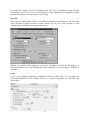
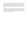
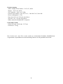
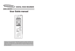
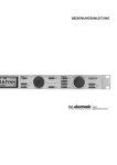
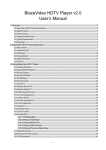
Operating Manual
English … page 2
Benutzerhandbuch
Deutsch … Seite 20
SAFETY INSTRUCTIONS
CAUTION: To reduce the risk of electrical shock, do not remove the cover or rear panel of
this unit. No user serviceable parts inside. Please refer servicing to qualified personnel only.
WARNING: To reduce the risk of fire or electrical shock do not expose this appliance to rain
or moisture.
SERVICING: The user should not attempt to service the appliance beyond that is described in
the Operating Instructions. All other servicing should be referred to qualified service
personnel.
ALL RIGHTS RESERVED © 2004 Swissonic
The information contained in this manual is subject to change without notice. No part of this
manual may be reproduced or transmitted in any form or by any means, electronic or
mechanical, including photocopying and recording of any kind, for any purpose, without the
express written permission of Swissonic.
2
Table of Contents
1.
Introduction ...................................................................................................................... 4
2.
Installation ........................................................................................................................ 5
3.
Rear Panel Connections................................................................................................... 6
3.1 GND Ground Pin Connector .............................................................................................. 6
3.2 Coaxial S/PDIF In- and Outputs ........................................................................................ 6
3.3 USB Connector .................................................................................................................. 6
3.4 Optical S/PDIF In- and Outputs ......................................................................................... 7
3.5 L&R Stereo Unbalanced & Balanced Audio Outputs........................................................ 7
3.6 L&R Stereo RCA Record Input and Outputs..................................................................... 7
3.7 Inserts (2x).......................................................................................................................... 8
4.
Front Panel Connections & Control Knobs/Switches................................................... 9
4.1 XLR Microphone Input Controls (2 x) .............................................................................. 9
4.2 Stereo Line Input Controls (2 x) ........................................................................................ 9
4.3 Phono Input Controls ....................................................................................................... 10
4.4 Stereo Headphone Amplifiers (2 x) ................................................................................. 10
4.5 Master Volume................................................................................................................. 11
4.6 Power Switch ................................................................................................................... 11
5.
Driver Installation .......................................................................................................... 12
5.1 Windows 98SE / ME / 2000 / XP .................................................................................... 12
5.2 Mac OS X......................................................................................................................... 12
6.
Application Guide .......................................................................................................... 13
6.1 The purpose of the USB Studio D Mk. II ........................................................................ 13
6.2 Usage as a recording interface ......................................................................................... 13
6.3 Usage as a standard mixer (standalone) ........................................................................... 14
6.4 Usage with common audio applications........................................................................... 14
7.
Specifications .................................................................................................................. 17
3
1.
Introduction
The new Swissonic USB Studio D Mk. II is the perfect solution in every home recording
environment. The unique and extremly flexible 24bit USB audio interface provides various
analog in- and outputs: 2 microphone inputs (balanced inputs with switchable phantom
power, peak lights, gain control and inserts), 4 mono (2 stereo) adjustable line level inputs, 2
stereo turntable (Phono) / CD (Line) inputs with level control, unbalanced and balanced stereo
outputs and 2 adjustable headphone outputs. In addition the USB Studio D Mk. II provides
digital S/PDIF in- and outputs with both coaxial RCA and optical TOSLink connectors.
The USB interface connects the USB Studio D Mk. II to your favourite recording software
running under Microsoft Windows 98 SE / ME / 2000 / XP (ASIO support) or Apple Mac OS
X (CoreAudio support). Each input source can be enabled for recording with your favourite
recording software. There's no need for a soundcard anymore – clever!
4
2.
Installation
Your USB Studio D Mk. II was carefully packed in the factory and the packaging was
designed to protect the unit from rough handling. Nevertheless, we recommend that you
carefully examine the packaging and its contents for any signs of physical damage, which
may have occurred in transit.
Rack Mounting
The USB Studio D Mk. II fits into one standard 19" rack unit of space. Be sure that there is
enough air space around the unit for cooling. As to avoid overheating, please do not place the
unit on high temperature devices such as power amplifiers.
Main Voltage
The USB Studio D Mk. II has a professional internal power supply thus eliminating the use of
external power adapters.
Before you connect the unit to the mains, please make sure that your local voltage matches the
voltage required by the unit!
5
3.
Rear Panel Connections
Please read the following to learn more about rear panel connections and their functions.
3.1
GND Ground Pin Connector
The ground pin connector allows for connection of your turntable grounding wire.
Please refer to your turntable manual for information regarding ground connections.
3.2
Coaxial S/PDIF In- and Outputs
There are two RCA connectors for coaxial S/PDIF connection.
These connectors allow you to connect S/PDIF devices such DAT recorders or digital mixers
with coaxial cables to the USB Studio D Mk. II.
3.3
USB Connector
The USB connector connects the USB Studio D Mk. II to the computer.
You can use the supplied standard USB cable that connects the unit to your PC or Macintosh
system.
6
3.4
Optical S/PDIF In- and Outputs
There are two TOSLink connectors for optical S/PDIF connection.
These connectors allow you to connect S/PDIF devices such MD recorders or digital mixers
with optical cables to the USB Studio D Mk. II.
3.5
L&R Stereo Unbalanced & Balanced Audio Outputs
The USB Studio D Mk. II provides two types of analog output connections for you to connect
to your monitoring device, unbalanced & balanced.
These are to connect to your active monitor speakers, amplifier, or additional mixer device for
you to listen to the output from the USB Studio D Mk. II.
This output signal carries the source signal from any/all of the inputs on the front of the USB
Studio D Mk. II, or a mixed signal including the inputs on the front of the USB Studio D Mk.
II and a source from the the REC inputs on the rear panel.
3.6
L&R Stereo RCA Record Input and Outputs
Use standard stereo RCA cables to connect the REC inputs and outputs to a possible
additional (optional) recording device of choice.
This could be a DAT or MD recorder for example. The REC outputs (L&R) connect to the
inputs of your chosen recording device, while the REC inputs are used for the return signal
from your recording devices outputs. You can use the REC Inputs and Outputs as alternative
to the USB interface when you want to use the USB Studio D Mk. II without a computer. The
REC outputs will always send out the same signal that is recorded with the computer via the
USB audio interface.
7
3.7
Inserts (2x)
There are two TRS Insert connectors for the two microphone preamps.
Inserts are optionally used to process the analog input signal in an external effect processor
before it is sent to the computer via USB. You may be familiar with the concept of inserts,
many standard mixing desks have inserts for example. If you never heard of effect inserts
before, you might be a bit confused – don’t worry, inserts are a very nice addition to this
product.
As mentioned, inserts allow you to use the microphone preamps of the USB Studio D Mk. II
for incoming signals, then run the signal through external hardware effects (e.g. a
compressor/limiter) before the signal is sent to the computer. In order to use the inserts, you
need a so-called "insert-cable", sometimes called "Y-cable", with a 1/4" TRS connector on
one and and two 1/4" mono connectors on the two other ends. If you have trouble to find such
a cable, contact your music retailer – they will certainly be able to help you. The TRS
connector gets plugged into the insert connector of the specific channel (1 or 2) of the USB
Studio D Mk. II. The 1/4" connector that is connected to the "tip" of the TRS connector gets
connected into the input of your effect processor. The 1/4" connector that is connected to the
"ring" of the TRS connector gets connected to the output of your effect processor (the
"sleeve" carries ground). So, every 1/4" insert connector is used for both, 'sending' and
'receiving' the signal. You need only one "insert-cable" per channel.
8
4.
Front Panel Connections & Control Knobs/Switches
The USB Studio D Mk. II has a multitude of audio connections and controls on the front
panel. Please read the following information to understand these connections.
4.1
XLR Microphone Input Controls (2 x)
Independent (2 x) rotary gain controls, switchable Phantom power, peak lights, and a
record/monitor enable switch.
This is where you can connect up to two microphones, control their input gain, and choose
either to monitor the signal directly to your main outputs for monitoring, or to send the source
to the REC outputs and subsequently to your computer via USB.
Connect a microphone using a standard XLR type microphone cable and turn up the volume
knob to an acceptable level. If your microphone is a condenser microphone that requires
phantom power, depress the DC48V switch to enable power to your mic.
The REC switch directs the microphone source signal to the USB interface and allows you to
record the signal with your computer when in the drepessed position. In that case, the signal
also will be sent to the REC output on the rear panel. When in the non-depressed position the
signal is routed to the main outputs on the rear panel for live input monitoring.
The peak light illuminates to indicate when the mic pre-amp is over-driven with excessive
input signal. If illuminated, reduce the volume to avoid distortion of your microphone signal.
4.2
Stereo Line Input Controls (2 x)
Independent (2 x) rotary volume controls, -20dB pad, and a record/monitor enable switch.
This is where you can connect up to two stereo (L&R) line level devices (keyboards, sound
modules, etc.), control their input gain, and choose either to monitor the signal directly to
your main outputs for monitoring, or to send the source to the REC outputs and subsequently
to your computer via USB.
Connect your stereo (L&R) line level device with a standard 1/4” audio cables and turn up the
volume knob to an acceptable level.
9
A -20dB PAD switch is provided to reduce the input gain on very high input signals. If your
signal is distorting, depress the -20dB switch to adjust to a more suitable level.
The REC switch directs the line level source signal to the USB interface and allows you to
record the signal with your computer when in the drepessed position. In that case, the signal
also will be sent to the REC output on the rear panel. When in the non-depressed position the
signal is routed to the main outputs on the rear panel for live input monitoring.
4.3
Phono Input Controls
Independent (2 x) rotary volume controls, line/phono switch, and a record/monitor enable
switch.
This is where you can connect up to two stereo phono/line level devices, control their input
gain, and choose either to monitor the signal directly to your main outputs for monitoring, or
to send the source to the REC outputs and subsequently to your computer via USB.
Connect your stereo (L&R) phone/line level device with a standard RCA audio cables and
turn up the volume knob to an acceptable level.
A line/phono switch is provided for each stereo pair of inputs which toggles the use of the
inputs as either a fully operational RIAA phono pre-amp or as standard RCA line level inputs.
The REC switch directs the phono/line level source signal to the USB interface and allows
you to record the signal with your computer when in the drepessed position. In that case, the
signal also will be sent to the REC output on the rear panel. When in the non-depressed
position the signal is routed to the main outputs on the rear panel for live input monitoring.
4.4
Stereo Headphone Amplifiers (2 x)
Independent (2 x) rotary monitor volume controls, and MIX/REC switch.
This is where you can connect up to two stereo headphones, control their volume, and choose
either to monitor the full monitor mix of your signals from both the front panel inputs and the
REC inputs together, or just the REC input signal from the rear panel (only what you are
recording). The MIX/REC switch toggles the monitor mode of the headphone amplifiers.
10
4.5
Master Volume
The master volume controls the main output level to the main outputs on the rear panel.
It does not effect the volume of the signal that you are recording via USB.
4.6
Power Switch
Power On/Off switch.
This is where you enable the unit for use.
11
5.
Driver Installation
The USB Studio D Mk. II works as professional USB recording device with Microsoft
Windows 98 SE / ME / 2000 / XP and Apple Mac OS X. You can use the unit with any
modern audio application after driver installation and initial setup. Please follow the
instructions in this chapter.
5.1
Windows 98SE / ME / 2000 / XP
Note: It is not recommended to connect the USB Studio D Mk. II before you install the driver.
Step 1
Under Windows 98SE or ME, you can launch the installer for the driver by launching
"Setup98ME.exe" from the included driver CD. Under Windows 2000 and XP, you need to
launch "Setup.exe" (make sure your are logged in as Administrator or with equivalent rights).
Step 2
Select your language.
Step 3
Click on "Install the driver".
Step 4
Agree to the terms of license for the driver.
Step 5
Now the installer does its job. Please follow the instructions on screen. You will be prompted
to connect your USB Studio D Mk. II to the computer. If the unit is already plugged in you
will be prompted to unplug it and then replug it again.
Step 6
There's some Windows popping up and disappearing again during installation, that's normal
Windows Plug & Play behaviour.
5.2
Mac OS X
Because of the excellent USB audio support in Mac OS X (from version 10.2 and above), you
do not need to install a special driver to use the USB Studio D Mk. II under Mac OS X. Just
connect the unit via USB after you have turned on the power and you are ready to use it.
To control the features of the USB Studio D Mk. II, you need to install the control panel
software from the supplied CD-ROM. Just copy the MacOSX_Driver archive file from the
supplied CD to a folder of your choice on your local hard disk. Now uncompress it and copy
the included control panel application to any folder you want.
12
6.
Application Guide
This chapter gives you an overview of typical applications for the USB Studio D Mk. II.
6.1
The purpose of the USB Studio D Mk. II
Nowadays, the computer is the hub of the home recording studio. There are many reasons for
this including ease of editing, clarity, digital transfer to CD etc. Traditionally, most computer
soundcards do not offer professional connectivity for microphones, turntables and the like. A
professional audio interface is required to provide these features. In the case of the turntables,
a seperate phono pre-amp is also required to record your analog vinyl records to your PC for
CD transfer. The USB Studio D Mk. II has been designed to cator for many of these needs.
The USB Studio D Mk. II provides a solution for users needing to connect a multitude of
different devices including condenser microphones which require phantom power, turntables,
keyboards, sound modules and even 2 sets of headphones for monitoring to any 2ch recording
device. This includes the computer, DAT recorders, MD recorders, etc.
With its professional 24bit USB audio interface, the USB Studio D Mk. II connects directly to
your computer, eliminating the need for an additional soundcard. Any modern computer has a
USB interface, from normal desktop systems to laptop / notebook computers. This allows you
to use the USB Studio D Mk. II even away from your home studio "on the road" if required.
6.2
Usage as a recording interface
In this example we will record an input from a microphone to the computer.
Step 1
Ensure you have connected the USB Studio D Mk. II via USB to your computer and that the
driver is installed as explained in chapter 5.
Step 2
Connect your microphone to one of the microphone connections on the front of the USB
Studio D Mk. II and increase the gain control to an acceptable level. See section 4.1 of this
manual.
Step 3
Depress the REC switch on the front panel of the USB Studio D Mk. II for the microphone
channel you are using to send the signal to the USB interface to your computer. This will
allow you to record the signal in your audio application.
Adjust the gain control on the microphone to the correct level desired. You should take note
of the input level meters of your recording software to make sure that you are recording at an
acceptable value.
Step 4
Engage recording in your favoite audio software to capture the signal from your microphone.
13
Note: To monitor your signal, simply listen to your monitor speakers (ensure they are
connected correctly as described in section 3.5) or headphones connected to the front panel of
the USB Studio D Mk. II (as described in section 4.4).
6.3
Usage as a standard mixer (standalone)
The USB Studio D Mk. II is extremely simple to operate as a standard mixer, even without
computer connection.
Step 1
Simply connect all your input devices to the appropriate connections on the front panel.
Step 2
Adjust the gain controls on the desired input signals to your desired level.
Step 3
Monitor the results from your speakers or headphones (check section 3.5 and 4.4).
6.4
Usage with common audio applications
Cubase SX/SL or Nuendo
When you use the USB Studio D Mk. II in ASIO compatible applications under Windows
such as Cubase SX / SL or Nuendo from Steinberg, you need to select the ASIO driver of the
unit inside the VST Multitrack setup dialog. The following screen shot shows Nuendo,
although it will look similar in other ASIO compatible applications:
If you click on Control Panel, you can change the hardware options and the buffer size
(which equals the latency) of the ASIO driver.
The Cubase SX / SL and Nuendo setup under Mac OS X is similar although you cannot call
the Control Panel from within the application (you need to launch that separatly if required).
14
Wavelab
When you use the USB Studio D Mk. II in MME compatible applications under Windows
such as Wavelab from Steinberg (or any other MME compatible application), you can select
the in- and output device somewhere in the audio settings inside the application.
Just select USB Audio Device for both recording and playback. In Wavelab, you can reach the
dialog shown above via Preferences > Audio Card.
Logic
Logic is the leading multichannel recording application under Mac OS X. It uses the
CoreAudio standard as most Mac OS X audio applications for recording and playback.
Launch Logic. After the software has been loaded, call Audio > Audio Hardware & Drivers
from the menu. The dialog that is displayed above will appear now. Make sure Core Audio is
checked. In the Driver selection box, you can select the driver. Please select the USB device
here. By default, Logic works with 16bit recording and playback resolution which is OK for
15
normal home recording. If you want to use 24bit resolution, make sure to check the box 20/24
Bit Recording.
Peak
Peak from BIAS is the leading stereo audio editor under Mac OS X. To use the USB Studio D
Mk. II in Peak, launch Peak and go to Audio > Sound Out and verify that CoreAudio is
selected. Go to Audio > Hardware Settings and select the USB Studio D Mk. II as your input
and output device. Now go to Audio>Record Settings>Device and Sample Format – you can
use the menu to select your bit depth, sample rate and other input settings.
16
7.
Specifications
Audio Inputs
- Connectors 1/4" jack TRS Balanced, XLR Balanced
- RCA Unbalaced
- Impedance 47k Ohms / 600Ohm
- Min Sensitivity -20dB
- Peak input level +16dB
Headphone Outputs
- Connectors 1/4" jack
- Type Stereo, 1V RMS @ 32 Ohm
Stereo Line Mixer Outputs
- Connectors 1/4" Jack Unbalanced
- Impedance 47K / -10dB
- Max. output level +2dB (peak level +18.5 dB)
XLR Balanced Outputs
- Connectors XLR
- Type balanced
- Min. output impedance 600Ohms
- Max. output level 0dB (peak level +18.5dB)
Dist, Freq, S/N Ratio & Crosstalk
- Frequency response 20Hz~20kHz, 0dB~-2B
- Distortion 0.008%
- S/N Ratio better than 74dB
- Crosstalk rejection >80dB@1kHz;-20dB input
Function Controls
- Volume per channel variable
USB Audio Interface
- supported samplerates: 32kHz, 44.1kHz, 48kHz
- ADC: AKM, 24bit, 64x Oversampling, 100dB(A) dynamic range, 100dB(A) S/N ratio
- DAC: AKM, 24bit, 128x Oversampling, 110dB(A) dynamic range, 110dB(A) S/N ratio
Digital I/O Interface
- 24bit Digital I/O with samplerate converter
- supported samplerates: 32kHz, 44.1kHz, 48kHz
- samplerate converter: 128dB dynamic range
17
Power Supply
- Mains voltages USA/Canada ~ 120 V AC, 60 Hz
- Europe ~ 230 V AC, 50 Hz
- U.K./Australia ~ 240 V AC, 50 Hz
- General export model ~ 100-120 V AC, ~ 200-240 V AC, 50-60 Hz
- Power consumption 11.5VA
- Fuse 100-120 V AC: 630 mA (slow-blow)
- 200-220 V AC: 315 mA (slow-blow)
- Mains connection Standard IEC receptacle
Physical
- Dimension 1 3/4" (44.5 mm) * 19" (482.6 mm) * 8 1/2" (217 mm)
- Net weight approx. 3.25 kg
Note: modifications may be made from time to time to existing products without prior notice.
Specifications and appearance may differ from those listed or shown.
18
19
SICHERHEITSHINWEIS
ACHTUNG: Entfernen Sie nie die Front- oder Rückabdeckung des Gerätes zur Vemeidung
eines Stromschlages. Es befinden sich keine Teile innerhalb des Gerätes die vom Benutzer
gewartet werden müßten. Zu Wartungszwecken wenden Sie sich immer an Fachpersonal.
WARNHINWEIS: Setzen Sie dieses Gerät nie Feuchtigkeit oder Nässe aus!
INSTANDHALTUNG: Versuchen Sie nie selbständig das Gerät zu warten, folgen Sie immer
den Anweisungen der Betriebsanleitung. Alle weiteren Instandhaltungsmaßnahmen sollten
immer von qualifiziertem Fachpersonal getätigt werden.
ALLE RECHTE VORBEHALTEN © 2004 Swissonic
Die Informationen die in dieser Anleitung enthalten sind können ohne Ankündigung
abgeändert werden. Diese Anleitung darf nicht kopiert oder vervielfältigt werden, weder
elektronisch noch mechanisch, z.B. fotokopiert oder aufgenommen, ohne ausdrückliche,
schriftliche Genehmigung der Firma Swissonic.
20
Inhaltsverzeichnis
1.
Einleitung ........................................................................................................................ 22
2.
Installation ...................................................................................................................... 23
3.
Rückseitige Anschlüsse .................................................................................................. 24
3.1 GND Erdung .................................................................................................................... 24
3.2 Koaxiale S/PDIF Ein- und Ausgänge............................................................................... 24
3.3 USB Anschluß.................................................................................................................. 24
3.4 Optische S/PDIF Ein- und Ausgänge............................................................................... 25
3.5 L&R Stereo Ausgänge, symmetrisch und unsymmetrisch............................................... 25
3.6 L&R Stereo Record Cinch Ein- und Ausgänge ............................................................... 25
3.8 Inserts (2x)........................................................................................................................ 26
4.
Verbindungen und Steuerelemente auf der Vorderseite ............................................ 27
4.1 XLR Mikrofon Eingänge (2x).......................................................................................... 27
4.2 Stereo Line Input Controls (2x) ....................................................................................... 27
4.2 Phono Eingang (Input) ..................................................................................................... 28
4.3 Stereo Kopfhörer Verstärker (2x) .................................................................................... 28
4.4 Master Volume (Systemlautstärke).................................................................................. 29
4.5 Power Schalter.................................................................................................................. 29
5.
Treiber Installation ........................................................................................................ 30
5.1 Windows 98SE / ME / 2000 / XP .................................................................................... 30
5.2 Mac OS X......................................................................................................................... 30
6.
Anwendungen ................................................................................................................. 31
6.1 Der Zweck des USB Studio D Mk. II .............................................................................. 31
6.2 Das USB Studio D Mk. II als Recording Interface (Aufnahme Schnittstelle)................. 31
6.3 Verwendung als Standard Mischer (Standalone) ............................................................. 32
6.4 Verwendung mit herkömmlicher Audio Software ........................................................... 32
7.
Spezifikationen ............................................................................................................... 35
21
1.
Einleitung
Das neue Swissonic USB Studio D Mk. II is die ideale Lösung für jedes Home Recording
Studio. Die einzigartige und extrem flexible 24Bit Audio-Schnittstelle verfügt über eine Reihe
von analogen Ein- und Ausgängen: 2 Mikrofoneingänge (symmetrischer Eingang mit
zuschaltbarer Phantomspeisung, Übersteuerungs-LED, regelbarem Vorverstärker und Inserts),
4 einstellbare Mono (2 Stereo) Line Eingängen, 2 Stereo Phono- Anschlüsse (Plattenspieler) /
CD (Line) Eingänge (regelbar), unsymmetrische und symmetrische Stereo Ausgänge und 2
regelbare Kopfhörerausgänge. Zusätzlich verfügt das USB Studio D Mk. II über digitale
S/PDIF Ein- und Ausgänge über koaxiale Cinchanschlüsse oder optisches Toslink.
Die USB Schnittstelle verbindet das USB Studio D Mk. II mit Ihrer Aufnahme Software auf
allen gängigen Plattformen, Windows 98SE / ME / 2000 / XP (ASIO) und Apple Mac OS X
(Core Audio). Sie können mit Ihrer Software von jedem zugewiesenen Eingang aufnehmen.
Sie brauchen keine Soundkarte mehr – Clever!
22
2.
Installation
Das USB Studio D Mk. II kommt in einer festen Verpackung, die das Gerät vor jeglicher
Beschädigung bewahren soll. Trotzdem sollten Sie vor Gebrauch, sowohl die Verpackung als
auch den Inhalt, auf eventuelle Beschädigungen hin überprüfen, die beim Versand enstanden
sein könnten.
Rackmontage
Das USB Studio D Mk. II paßt in ein Standard 19" Rack, sorgen Sie lediglich dafür, daß um
das Gerät herum genug Platz vorhanden ist um ausreichende Kühlung zu gewährleisten. Um
Überhitzung zu vermeiden sollten Sie das Gerät nie unmittelbar über einem anderen
hitzeabstrahlenden Gerät, z.B. Verstärker, montieren.
Stromversorgung
Das USB Studio D Mk. II verfügt über ein hochwertiges internes Netzteil, das einen externen
Netzadapter überflüssig macht.
Bitte vergewissern Sie sich vor dem Anschluß des Gerätes an die Stromversorgung immer
erst, daß die örtliche Spannung mit den Anforderungen des Gerätes übereinstimmt.
23
3.
Rückseitige Anschlüsse
Bitte lesen Sie die folgenden Abschnitte sorgfältig, um mehr über die rückseitigen Anschlüsse
des Gerätes und deren Funktionen zu erfahren.
3.1
GND Erdung
Der GND Anschluß gibt Ihnen die Möglichkeit die Erdung eines Plattenspieler anzuschließen.
Weitere Informationen bezüglich der Erdung Ihres Plattenspielers entnehmen Sie bitte der
dazu gehörigen Anleitung.
3.2
Koaxiale S/PDIF Ein- und Ausgänge
Das USB Studio D Mk. II verfügt über zwei Cinch-Buchsen für koaxialen S/PDIF Anschluß.
Mit diesen beiden Anschlüssen können Sie S/PDIF Geräte, z.B. DAT Recorder oder digitale
Mischpulte, mit koaxialen Kabeln an das USB Studio D Mk. II anschließen.
3.3
USB Anschluß
Der USB Anschluß verbindet das USB Studio D Mk. II mit Ihrem Computer.
Sie können hierfür das mitgelieferte Standard USB Kabel verwenden, um das Gerät mit Ihrem
PC oder Mac zu verbinden.
24
3.4
Optische S/PDIF Ein- und Ausgänge
Das Gerät verfügt über zwei Toslink Anschlüsse für eine optische S/PDIF-Verbindung.
Mit Hilfe dieser Anschlüsse können Sie S/PDIF Geräte, wie MD Recorder oder digitale
Mischpulte, mit optischen Kabeln an Ihr USB Studio D Mk. II anschließen.
3.5
L&R Stereo Ausgänge, symmetrisch und unsymmetrisch
Das USB Studio D Mk. II bietet zwei Arten von analogen Ausgängen um Ihre Monitore
anzuschließen, symmetrisch (balanced) und unsymmetrisch (unbalanced).
Hier können Sie Ihre aktiven Monitore, Ihren Verstärker oder einen zusätzlichen Mixer
anschließen, um das Ausgangssignal Ihres USB Studio D Mk. II abzuhören.
Der Output kann ein oder alle Eingangssignal(e) wiedergeben, die an der Vorderseite des
USB Studio D Mk. II angelegt sind, oder aber eine Mischung aus den Eingängen an der
Vorderseite und einer Signalquelle, die an der Rückseite am REC Eingang anliegt.
3.6
L&R Stereo Record Cinch Ein- und Ausgänge
Verwenden Sie Standard Cinch Kabel um zusätzliche Aufnahmegeräte an den REC Ein- und
Ausgängen anzuschließen. Hierbei kann es sich zum Beispiel um einen DAT oder MD
Recorder handeln.
Die REC Ausgänge (L&R) werden direkt an die Eingänge Ihres Aufnahmegerätes
angeschlossen. Gleichzeitig werden die Ausgänge des Aufnahmegerätes mit den REC
Eingängen Ihres USB Studio D Mk. II verbunden. Sie können die REC Ein- und Ausgänge
auch alternativ verwenden wenn Sie das USB Studio D Mk. II “Stand alone“ (ohne den
Computer) benutzen möchten.
25
3.8
Inserts (2 x)
Sie haben zwei TRS Insert Anschlüsse, für die zwei Mikrofon Preamps, zur Verfügung.
Inserts können eingesetzt werden, um ein analoges Eingangssignal in einem externen
Effektgerät zu bearbeiten, ehe es per USB an den Rechner geschickt wird. Möglicherweise
sind Sie bereits mit dem Prinzip von Inserts vertraut, wenn Sie schon mit analogen
Mischpulten gearbeitet haben. Falls Inserts für Sie Neuland darstellen sollten, keine Angst, sie
Stellen eine sehr angenehme Bereicherung dar.
Wie bereits angesprochen, ermöglichen die Inserts, ein Eingangssignal vom Mikrofon Preamp
des USB Studio D Mk. II an ein externes Effektgerät (z.B. Kompressor/Limiter) zu senden,
bevor es an den Computer geschickt wird. Um die Inserts verwenden zu können, brauche Sie
ein so genanntes Insert-Kabel, auch Y-Kabel genannt, mit einer 6,3mm Stereo Klinke auf der
einen Seite, und zwei 6,3mm Klinken an den anderen beiden Enden. Sie finden diese Kabel
bei jedem guten Musikgeschäft. Die Stereoklinke wird in die jeweilige Insert-Buchse des
Kanals (1 oder 2) des USB Studio D Mk. II gesteckt. Die 6,3mm Klinke die mit der Spitze der
Stereoklinke verbunden ist, wird in den Eingang (Input) Ihres Effektgerätes gesteckt, während
die andere mono Klinke mit dem Ausgang Ihres Effektgerätes verbunden wird. Dem zufolge
wird jeder Insert sowohl für das Senden von Signalen verwendet, als auch für das Empfangen
derselben. Man braucht also nur ein Insertkabel pro Kanal.
26
4.
Verbindungen und Steuerelemente auf der Vorderseite
Auf der Vorderseite des USB Studio D Mk. II befinden sich eine ganze Reihe von
Verbindungen und Schaltern. Bitte lesen Sie die folgenden Informationen sorgfältig um diese
zu verstehen.
4.1
XLR Mikrofon Eingänge (2 x)
Unabhängige (2x) Drehregler, zuschaltbare Phantomspeisung, Übersteuerungs LED,
Aufnahme/ Monitor Schalter.
Hier können Sie zwei Mikrofone anschließen, ihren Eingangspegel einstellen und
entscheiden, ob Sie diese über den Main Output direkt abhören, das Signal direkt an den REC
Ausgang oder an den Computer, über die USB Verbindung, schicken wollen.
Schließen Sie ein Mikrofon mit einem standard XLR Kabel an und drehen Sie die Lautstärke
auf einen akzeptablen Level auf. Wenn Sie ein Kondensator Mikrofon verwenden, müssen Sie
zusätzlich den Knopf für Phantomspeisung (DC 48V) aktivieren, da diese Art von
Mikrofonen eine zusätzliche Spannungsversorgung benötigen, die in diesem Modus über das
Kabel läuft.
Wenn der REC Schalter aktiviert ist, wird das Mikrofonsignal direkt an die USB Schnittstelle
gesendet, und Sie können es in Ihrem Computer aufnehmen. In diesem Fall wird wird das
Signal gleichzeitig auch an die REC Ausgänge auf der Rückseite des Rechners geschickt.
Wenn der Knopf gedrückt ist, wird das Signal direkt an die Main Outputs (Ausgänge)
gesendet, um direktes mithören (monitoring) zu ermöglichen.
Die Übersteuerungs LED zeigt an, wenn der Mikrofon Preamp zu sehr aufgedreht und
dadurch das Eingangssignal zu kräftig ist.
4.2
Stereo Line Input Controls (2 x)
Voneinander unabhängige Lautstärkeregelung (Volume Controls), -20dB Pad (Puffer),
Record/Monitor Schalter.
Hier können Sie zwei Geräte (L&R) mit Line Pegel (Keyboard, Sound Modul, etc.) a
anschließen und den Eingangspegel aussteuern. Das Signal können Sie entweder direkt auf
27
den Main Outs abhören, oder aber für die Aufnahme an die REC Outs oder via USB den
Computer schicken.
Schließen Sie Ihr Stereo Line Gerät mit 6,3mm Klinkenkabeln (L&R) an und drehen Sie die
Lautstärke auf.
Der –20dB Pad kann zugeschaltet werden um extreme Eingangssignale zu reduzieren. Wenn
das Signal verzerrt, drücken Sie den –20dB Schalter um einen besseren Pegel zu erhalten.
Wenn der REC Schalter eingedrückt ist, wird das Signal direkt an die Main Outputs auf der
Rückseite geschickt was ein direktes Monitoring ermöglicht. Wenn der REC Knopf nicht
gedrückt ist, kann das Signal über USB direkt auf dem Computer aufgenommen werden. In
diesem Fall wird das Signal zusätzlich an den REC Out geschickt.
4.2
Phono Eingang (Input)
Zwei voneinander unabhängige
Record/Monitor Schalter
Lautstärkeregler
(Volume),
Line/Phono
Schalter,
Hier können Sie zwei Stereo Phono/Line Level Geräte anschließen und den Eingangspegel
aussteuern. Das Signal können Sie entweder direkt auf den Main Outs abhören, oder aber für
die Aufnahme an die REC Outs oder via USB den Computer schicken
Schließen Sie Ihr Stereo / Phono Line Gerät mit 6,3mm Klinkenkabeln (L&R) an und drehen
Sie die Lautstärke auf.
Ein Line/Phono Schalter an jedem Stereo Eingang sorgt dafür, daß, je nach Stellung, der
Eingang entweder als voll funktionsfähiger RIAA Phono Vorverstärker arbeitet, oder aber als
Normaler Cinch Eingang mit Line-Pegel.
Wenn der REC Schalter eingedrückt ist, wird das Signal direkt an die Main Outputs auf der
Rückseite geschickt was ein direktes Monitoring ermöglicht. Wenn der REC Knopf nicht
gedrückt ist, kann das Signal über USB direkt auf dem Computer aufgenommen werden. In
diesem Fall wird das Signal zusätzlich an den REC Out geschickt.
4.3
Stereo Kopfhörer Verstärker (2 x)
Voneinander unabhängige Lautstärkeregler, MIX/REC Schalter
28
Hier kann man zwei Stereo Kopfhörer anschließen, die Lautstärke regeln, und wahlweise
entweder den kompletten Monitor Mix (Wiedergabe und Aufnahme), oder nur das REC
Eingangssignal (die tatsächliche Aufnahme) abhören. Der MIX/REC Schalter regelt das
Monitoring des Kopfhörer Verstärkers.
4.4
Master Volume (Systemlautstärke)
Der Master Regler reguliert den Main Output Pegel (Gesamtlautstärke) auf der Rückseite des
Geräts.
Es beinflußt jedoch nicht die Lautstärke (Signalpegel) des Signals, das über USB
aufgenommen wird.
4.5
Power Schalter
Ein-/Ausschalter.
Hier schaltet man das Gerät ein.
29
5.
Treiber Installation
Das USB Studio D Mk. II ist eine professionelle USB Schnittstelle die mit Microsoft
Windows 98SE / ME / 2000 / XP und Apple Mac OS X betrieben werden kann. Nach der
Installation der Treiber und nach Anschluß, kann man das Gerät in allen modernen Audio
Anwendungen benutzen. Folgen Sie einfach den Anweisungen in diesem Kapitel.
5.1
Windows 98SE / ME / 2000 / XP
Hinweis: Bitte beachten Sie, daß zuerst die Treiber installiert werden müssen, bevor Sie das
Gerät anschließen.
Schritt 1
Unter Windows 98SE / Me starten Sie einfach “Setup98ME.exe“ von der Treiber CD. Unter
Windows 2000 / XP starten Sie “Setup.exe“ von der Treiber CD (bitte beachten Sie, daß Sie
als Administrator eingeloggt sind oder als User mit den gleichen Rechten)
Schritt 2
Wählen Sie die Sprache aus.
Schritt 3
Klicken Sie auf “Treiber installieren“.
Schritt 4
Bitte bestätigen Sie, daß Sie mit den Lizensbedingungen einverstanden sind.
Schritt 5
Der Installer übernimmt den Rest, folgen Sie einfach den Anweisungen auf dem Bildschirm.
Sie werden nun aufgefordert das USB Studio D Mk. II an den Rechner anzuschließen. Falls
das Gerät schon angeschlossen sein sollte, werden Sie dazu aufgefordert, es erst noch einmal
zu entfernen, um es dann neu anzuschließen.
Schritt 6
Während der Installation werden möglicherweise diverse Windows-Fenster angezeigt. Lassen
Sie sich davon nicht beirren, das ist normales Windows Verhalten.
5.2
Mac OS X
Wenn Sie einen Mac Version 10.2 und höher verwenden, müssen Sie keine extra Treiber
installieren, dank der hervorragenden USB Audio Unterstützung. Schließen Sie nach
Einschalten des Rechners lediglich das USB Studio D Mk. II an und Sie können loslegen.
Um die Eigenschaften des USB Studio D Mk. II einstellen zu können, müssen Sie die Control
Panel Software von der beiliegenden CD-Rom installieren. Kopieren Sie einfach die Mac OS
X Archiv Datei von der CD-Rom in eine Datei Ihrer Wahl auf Ihrer Festplatte. Nun müssen
Sie das ganze noch entpacken und die beigefügten Systemsteuerungs- Anwendungen in eine
Datei Ihrer Wahl kopieren.
30
6.
Anwendungen
Dieses Kapitel gibt Ihnen einen Überblick zu typischen Anwendungen mit dem USB Studio D
Mk. II.
6.1
Der Zweck des USB Studio D Mk. II
Heutzutage stellt der Computer die Schaltzentrale eines Homerecording Studios dar. Dafür
gibt es viele Gründe, z.B. einfaches Editieren, Klarheit, digitaler Transfer auf CD, usw.
Normalerweise bieten die meißten Computer Soundkarten keine professionellen Anschlüsse
für Mikrofone, Plattenspieler, etc. Man benötigt ein professionelles Audio Interface
(Schnittstelle) um das zu ermöglichen. Bei einem Plattenspieler bedarf es zusätzlich eines
Vorverstärkers um analoge Vinyl Schallplatten auf den Rechner, und dann auf CD zu
kopieren. Das USB Studio D Mk. II ist dafür ausgerichtet, möglichst viele dieser
Anwendungen zu ermöglichen.
Das USB Studio D Mk. II bietet eine Vielzahl von Lösungen für diverse Anwendungen, unter
anderem den Anschluß von Kondensator Mikrofonen, die Phantomspeisung benötigen,
Plattenspieler, Keyboards, Sound Module und sogar zwei Kopfhörer-Ausgänge für das
Monitoring von Aufnahmen. Man kann damit auf jegliche 2-Spur Geräte aufnehmen, DAT,
Computer, MD Recorder, etc.
Durch seine professionelle 24Bit USB Audio Schnittstelle kann das USB Studio D Mk. II
direkt an den Computer angesschlossen werden, was eine zusätzliche Soundkarte überflüssig
macht. Jeder moderne Computer verfügt über einen USB Anschluß, sowohl Desktops als auch
Laptops/Notebooks. Dadurch kann das USB Studio D Mk. II auch unterwegs verwendet
werden.
6.2
Das USB Studio D Mk. II als Recording Interface (Aufnahme Schnittstelle)
In diesem Beispiel zeigen wir, wie man ein ein Mikrofonsignal auf den Computer aufnimmt.
Schritt 1
Versichern Sie sich, daß das USB Studio D Mk. II über USB an Ihren Computer
angeschlossen ist und die Treiber, wie in Kapitel 5 beschrieben, installiert sind.
Schritt 2
Schließen Sie Ihr Mikrofon an einen der Mikrofoneingänge an der Vorderseite des USB
Studio D Mk. II und drehen Sie den Volume Regler auf einen vernünftigen Pegel auf (s.a.
Kapitel 4.1).
Schritt 3
Versichern Sie sich, daß der REC Schalter an der Vorderseite des USB Studio D Mk. II
gedrückt ist, so daß das Signal an das USB Interface Ihres Computers geschickt wird. Nun
können Sie ein Signal in Ihrer Audio Software aufnehmen.
Stellen Sie den Gain Regler des Mikrofoneinganges auf den von Ihnen gewünschten Pegel
ein. Achten Sie bei Ihrer Recording Software darauf, daß Sie einen guten Pegel aufnehmen.
31
Schritt 4
Stellen Sie die Audio Software auf Recording um das Signal Ihres Mikrofons aufzunehmen.
Anmerkung: Hören Sie einfach auf das Audiosignal aus Ihren Monitore (Lautsprecher) oder
den angeschlossenen Kopfhörern um Ihr Signal zu überwachen.
6.3
Verwendung als Standard Mischer (Standalone)
Das USB Studio D Mk. II kann auch ohne Computeranbindung ganz einfach als Standalone
Mischer verwendet werden.
Schritt 1
Schließen Sie einfach Ihre ganzen Geräte an die passenden Anschlüße an der Vorderseite an.
Schritt 2
Regeln Sie das Eingangssignal des benötigten Anschlusses auf den erwünschten Pegel.
Schritt 3
Überwachen Sie das Ergebnis über Monitore oder Kopfhörer.
6.4
Verwendung mit herkömmlicher Audio Software
Cubase SX/SL oder Nuendo
Wenn Sie das USB Studio D Mk. II mit ASIO kompatiblen Anwendungen in Windows
verwenden wollen, z.B. Cubase SX/SL oder Nuendo, müssen Sie den ASIO Treiber des
Gerätes im VST Multitrack Setup Dialog anwählen. Der Screenshot unten zeigt Nuendo, sieht
aber in allen ASIO kompatiblen Programmen ähnlich aussehen:
Wenn Sie auf Control Panel (Systemsteuerung) klicken, können Sie die Hardware Optionen
und Buffer Size (entspricht der Latenz) des ASIO Treibers einstellen.
32
Das Setup für Cuabase SX/SL und Nuendo unter Mac OS X ist ähnlich, jedoch mit dem
Unterschied, daß Sie die Control Panel Software nicht innerhalb des Programms starten
können (Sie müssen sie separat starten, wenn nötig).
Wavelab
Wenn Sie das USB Studio D Mk. II in MME kompatiblen Anwendungen (z.B. Wavelab)
unter Windows benutzen benutzen wollen, können Sie die Ein- und Ausgänge in den
Audiosettings innerhalb des Programms zuweisen.
Wählen Sie einfach USB Audiogerät sowohl für Aufnahme als auch für Wiedergabe. In
Wavelab kommen Sie zu dem Dialogfenster oben, indem Sie Voreinstellungen > Soundkarte
anwählen.
Logic
Logic is die wichtigste Mehrkanal Aufnahme Software für Mac OS X. Es verwendet den
CoreAudio.Standard wie die meißten Mac OS X Audio Programme für Aufnahme und
Wiedergabe.
33
Starten Sie Logic. Nachdem die Software geladen ist, rufen Sie Audio > Audio Hardware &
Treiber vom Menü auf. Der oben dargestellte Dialog erscheint nun. Versichern Sie sich, daß
Core Audio aktiviert ist. In dem Treiber Auswahlkästchen können Sie den Treiber anwählen.
Wählen Sie bitte das USB Gerät. In der Grundeinstellung arbeitet Logic mit 16Bit Aufnahme
und Wiedergabe was für gewöhnliches Homerecording durchaus ausreichend ist. Wenn Sie
die 24Bit Auflösung nutzen möchten, müssen Sie den Kasten 20/24Bit Aufnahme auswählen.
Peak
Peak von BIAS ist der führende Stereo Audio Editor für Mac OS X. Um das USB Studio D
Mk. II in Peak zu verwenden, gehen Sie auf Audio > Sound Out und sorgen Sie dafür, daß
CoreAudio angewählt ist. Gehen Sie danach auf Audio > Hardware Settings und stellen Sie
das USB Studio D Mk. II als Eingangs- und Ausgangsgerät ein. Gehen Sie nun zu Audio >
Record Settings > Device und Sample Format – Sie können im Menü Bit-Tiefe, Sample
Frequenz und andere Einstellungen verändern.
34
7.
Spezifikationen
Audio Eingänge
- Symmetrische 6,3mm Klinke, symmetrische XLR
- Unsymmetrische Cinch-Eingänge
- Impedanz 47Kohm / 600 Ohm
- Min. Sensibilität –20dB
- Max. Eingangssignal +16dB
Kopfhörerausgang
- 6,3mm Klinke
- Stereo, 1V RMS @ 32 Ohm
Stereo Line Miscger Output
- Unsymmetrische 6,3mm Klinke
- Impedanz 47K / -10dB
- Max. Ausgangssignal +2dB (peak level +18.5 dB)
Symmetrische XLR Ausgänge
- XLR Anschlüsse
- symmetrisch
- Min. Ausgangsimpedanz 600 Ohm
- Max. Ausgangssignal 0dB (peak level +18.5dB)
Distortion, Frequenz, Rauschabstand & Crosstalk
- Frequenzbereich 20Hz~20kHz, 0dB~-2B
- Distortion 0.008%
- Mehr als 74dB Rauschabstand
- Crosstalk Rejection >80dB@1kHz;-20dB input
Funktionen
- Lautstärke Einstellbar pro Kanal
USB Audio Schnittstelle (Interface)
- unterstützte Samplefrequenzen: 32kHz, 44.1kHz, 48kHz
- ADC: AKM, 24bit, 64x Oversampling, 100dB(A) Dynamik, 100dB(A) Rauschabstand
- DAC:AKM, 24bit, 128x Oversampling, 110dB(A) Dynamik, 110dB(A) Rauschabstand
Digital I/O Interface
- 24bit Digital I/O mit Sampleratenwandler
- unterstützte Samplefrequenzen: 32kHz, 44.1kHz, 48kHz
- Sampleratenwandler: 128dB Dynamikumfang
35
Stromversorgung
- Mains voltages USA/Canada ~ 120 V AC, 60 Hz
- Europe ~ 230 V AC, 50 Hz
- U.K./Australia ~ 240 V AC, 50 Hz
- General export model ~ 100-120 V AC, ~ 200-240 V AC, 50-60 Hz
- Power consumption 11.5VA
- Fuse 100-120 V AC: 630 mA (slow-blow)
- 200-220 V AC: 315 mA (slow-blow)
- Mains connection Standard IEC receptacle
Größe und Gewicht
- Größe 44.5 mm * 482.6 mm * 217 mm
- Gewicht ca. 3.25 kg
Bitte beachten Sie: Von Zeit zu Zeit werden an existierenden Produkten Modifikationen
vorgenommen. Spezifikationen und Erscheinung können von den genannten abweichen.
36