1
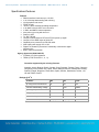
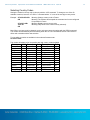
Xpert/XLite Voice Modem 8080-0005-1B & -2B OPERATIONS & MAINTENANCE MANUAL Part No. 8800-1178 Rev A January 2011 Sutron Corporation | 22400 Davis Drive | Sterling, VA 20164 | 703.406.2800 | www.sutron.com | [email protected] Sutron Corporation Xpert/XLite Voice Modem Users Manual #8800-1178 Rev A 01/2011 1 Sutron Voice Modem Operation Manual Models: 8080-0005-1B and -2B TABLE OF CONTENTS Overview ...................................................................................................................................................... 1 Jumpers and Connections ............................................................................................................................ 2 DB-9 serial connector ................................................................................................................................ 2 External power and grounding .................................................................................................................. 2 Recommended Jumper Settings ............................................................................................................... 3 Operation with the Xpert/XLite ...................................................................................................................... 4 Operation with Xpert- NIFC option (-2 model) .............................................................................................. 6 Connection to BK Radio ............................................................................................................................ 6 Operation with a PC ...................................................................................................................................... 7 Operation with SUTRON Sensors and loggers – SDR, Bubbler, Monitor .................................................... 7 Auto power on mode ..................................................................................................................................... 7 Testing/troubleshooting the modem with an Xpert or XLITE ........................................................................ 8 Compliance Information ................................................................................................................................ 9 Specifications/Features ............................................................................................................................... 10 Selecting Country Codes ............................................................................................................................ 11 Overview The 8080-0005-1B is a telephone modem designed for voice and data communications with Sutron’s data recorders. (The 8080-0005-2B is a special version designed to interface to a radio instead of a telephone line and requires the Xpert/XLite to be configured for fire weather operations). The 80800005 offers the features commonly offered by standard modern modems along with some special powersaving features. These features include: RS232 interface, baud rate up to 115,200 V.34, 33.6 kbps data sending and receiving Voice playback and record DTMF decode o o -40 C to +60 C extended operating temperature V.42, MNP 2-4 and 10-EC error correction V.42bis, and MNP-5 data compression Auto power up on ring with time out. Power up LED TX, RX, CD leds Jumper to select between DTR and RTS for power up signal Jumper to force DSR output to follow CD Capability to be powered over RS-232 cable. Wide input power supply of 5 to 16V. Digital Line Guard for protection if accidentally connected to digital telephone line Built in transient protection 8800-1178 Xpert Voice Modem Operation Manual – Rev A 1 Sutron Corporation Xpert/XLite Voice Modem Users Manual #8800-1178 Rev A 01/2011 2 Jumpers and Connections DB-9 serial connector The modem is designed with a DB9 Female DCE connection. This allows the modem to be connected directly to DTE devices such as the Xpert and XLite or a PC using a straight cable. Jumpers allow the DTE device to provide power to the modem through pin 9 of the DB9 connector. For connection to devices that can not provide power on pin 9, there is also separate power connector. . DB-9 PIN ASSIGNMENTS Pin 1. 2. 3. 4. 5. 6. 7. 8 9. Name CD RD TX DTR GND DSR RTS CTS RI or PWR IN (set by J3) Direction Out Out In Out GND Out In Out Out or In External power and grounding The modem has a three position terminal block to provide easy connections for power and for earth grounding of the modem. Label G + Function Earth ground – ground for internal transient protection. Grounding can also be achieved by mounting the modem to a grounded metal plate via the two mounting screws on the back of the modem. Power supply ground. Should be at the same potential as the RS-232 ground (Pin 5 of the DB-9). Supply voltage, 5 to 16 VDC. Power can either be supplied via this terminal or via pin 9 of the DB-9 connector. If power is supplied from both, modem will pull power from the higher voltage. Note: If using the two mounting screws on the rear of the modem to provide the earth ground for the unit, the screws threads should be 6-32. The two screws have a separation of 3 inches. In addition, the screws should protrude no more than on half inch into the case. Note: While the internal transient protection provides a high degree of ruggedness to the unit, it is not intended to replace the heavy duty external telephone line transient protection that is needed in more remote locations. 8800-1178 Xpert Voice Modem Operation Manual – Rev A 2 Sutron Corporation Xpert/XLite Voice Modem Users Manual #8800-1178 Rev A 01/2011 3 Recommended Jumper Settings JUMPER JUMPER POSITION Function J5 DSR 1-2 2-3 J4 Wake-up J3 Pin 9 use FACTORY DEFAULTS XPERT XLITE DSR=CD DSR=DSR (normal) X X 1-2 2-3 Wake on RTS Wake on DTR X X 1-2 2-3 RI out Power in X X SDR MONITOR 8210 X X X X X X Note: Sutron’s products do not require the RI signal and J3 should be left in the factory default position of 2-3. If using the modem with a device/software that requires RI to announce an incoming call, change J3 to position 1-2. 8800-1178 Xpert Voice Modem Operation Manual – Rev A 3 Sutron Corporation Xpert/XLite Voice Modem Users Manual #8800-1178 Rev A 01/2011 4 Operation with the Xpert/XLite You must configure the Xpert/XLite in order to use the modem connected to one of the serial ports. The modem can connect to any of the serial ports; however, Sutron recommends using COM3. COM2 is typically used for SATLINK and COM1 is typically used for a direct laptop connection. From the factory, the Xpert and XLite will be configured to supply +5V from pin 9 of COM 3 and the modem will be configured to be powered through the DB-9. This arrangement will make it possible to use one RS-232 cable to both power the modem and to communicate. Refer to the Xpert manual for details if power needs to be configured on for the comport or for more detailed instructions on the following steps. The following example assumes the modem will be connected to COM3. The first thing to do is to edit the autoexec.bat file to support the modem. This is done by adding or editing the line where the “remote” program is run. Note: you create or edit the file on your PC and then use XTERM to transfer the file to the Xpert. Adding the text “voice3:115200” tells remote that there will be a Sutron modem connected to COM3 and to use a baud rate of 115200. A typical autoexec.bat appears as follows: \windows\remote com1:115200 voice3:115200 \flash disk\xpert OPTIONAL: For advanced customization of how the modem works, create an initialization file for the modem (e.g. scom3.ini). The modem by default is initialized so that when it powers up it will not echo characters, will not provide result codes, and will ignore DTR. Remote.exe will send the contents of the init file to the modem when it starts. A typical init file for the Sutron modem is: ATS0=1 ATE0Q1&D0&W Be sure there is a CR at the end of the last line in the file or the program will ignore the line. Again, you create or edit the scomx.ini file on your PC and then use Xterm to transfer the file to the Xpert. The meaning of each setting is: S0=1 answer on first ring E0 don’t echo characters Q1 don’t send result codes &D0 ignore DTR &W save settings into profile. In the Setup of the Xpert/Xlite, add a COMS TAG to each data point that is needed, optionally add an ALARM block in front of the COMS TAG to trigger and send alarm data. Edit COMS TAG/ALARMS with appropriate data. Next, set up the Xpert/Xlite control panel COMS entry. Select Coms and change COM3 to VOICE. Once the VOICE is selected for COM3, a plus sign will allow the VOICE3 to be configured. Set answer mode, number of rings and language. Set phone number(s), number of redials and the redial delay (for alarms) 8800-1178 Xpert Voice Modem Operation Manual – Rev A 4 Sutron Corporation Xpert/XLite Voice Modem Users Manual #8800-1178 Rev A 01/2011 5 For voice mode: Select/add additional voice files for specfic sensors(Prefix) and units(Suffix). Edit the dial-out message (for alarms) Edit the dial-in message Example dial-in message. Speak prefix, data, suffix and alarm status for three sensors, then to hang up. SpeakPhrase Hello welcome to the Sutron xpert Pause 2.0 SpeakTag RAIN Pause 2.0 SpeakTag ELEVATION Pause 2.0 SpeakTag LEVEL Hangup For data mode: Nothing else needs configured. 8800-1178 Xpert Voice Modem Operation Manual – Rev A 5 Sutron Corporation Xpert/XLite Voice Modem Users Manual #8800-1178 Rev A 01/2011 6 Operation with Xpert- NIFC option (-2 model) When using the NIFC version (-2) the modem becomes an interface between an Xpert and a radio. It allows an operator to remotely "wake up" an Xpert Station with a remote Radio with DTMF keypad. The operator enters the unique station id of interest, and then listens to a pre-programmed set of sensor values. The modem decodes the DTMF tones and provides the speech playback capabilities for the Xpert Station. With this option, the modem DOES NOT operate as a normal phone line modem and SHOULD NOT be connected to a phone line. The validation of the Station ID and the configuration of the sensors to read back are all handled by the Xpert application software. Refer to the appropriate Xpert or 9210 Users manual for detailed set-up instructions. The modem jumpers should be set to connect to an Xpert (see jumper table above) to operate with the Xpert and BK radio. Connection to BK Radio The 8080-0005-2 can be connected to a BK radio. A drawing of the RJ11 connector on the modem and the connections to the radio are shown below: RJ-11 connector 1 2 3 4 5 6 (Black T2) (Red Ring) (Green Tip) (Yellow R2) BK Radio Accessories Connector Radio Ext Speaker Signal direction No Connect 3 (ground) No Connect No Connect Ground reference Audio into modem Audio out of modem 4 (mic audio) Ext Speaker signal 8800-1178 Xpert Voice Modem Operation Manual – Rev A 6 Sutron Corporation Xpert/XLite Voice Modem Users Manual #8800-1178 Rev A 01/2011 7 Operation with a PC Connect modem to external power (5 to 16V DC) since a PC does not supply power on pin 9. Connect to a standard serial port on a PC. With the exception of the auto power on mode explained below, the modem will operate as a standard modem. Operation with SUTRON Sensors and loggers – SDR, Bubbler, Monitor The instructions here are the general instructions for configuring and connecting the 8080-0005-1B modem to these products written from the modem’s perspective. For more in depth details on the specifics for each product when working with a modem, please refer to appropriate product manual. The default settings from Sutron for the modem will typically work. If the settings have been changed and need to be reset, connect the modem to a PC (see above) or other device and issue these commands to the modem: AT&F ATS0=1 ATE0Q1&D0&W This is what the commands mean: AT&F set to factory defaults S0=1 answer on first ring E0 don't echo characters Q1 don't send result codes &D0 ignore DTR &W save settings into profile. A null modem cable is needed between the device and the modem since they are both configured as DCE devices. If the null modem cable routes pin 9 through from end to end, you can power the modem from the device, but most null modem adapters leave pin 9 disconnected. In that case, just connect the power (5V-16V DC) to the power connector. Note: this can be done even if the cable routes power through pin 9. The modem will utilize which ever is providing the higher voltage. The modem also must be configured to power up in RTS instead of DTR and to output CD on the DSR pin. Set J4 to pins 1-2 to have the modem wake up on RTS Set J5 to pins 1-2 to route CD out the DSR pin Auto power on mode The modem enters a power-down mode when DTR is low (J3 in default 2-3 position. If in the 1-2 position, then RTS). In this mode, the power is turned off to the modem thus conserving the 360 mW that the modem would otherwise use. When a ring is detected on the phone line, the power is automatically turned on to the modem. This power-on sequence takes about 3 seconds, at which time the modem will be fully active. Typically, the modem will then answer the phone on the next ring (S0=1) to make a connection with the calling modem. 8800-1178 Xpert Voice Modem Operation Manual – Rev A 7 Sutron Corporation Xpert/XLite Voice Modem Users Manual #8800-1178 Rev A 01/2011 8 Testing/troubleshooting the modem with an Xpert or XLITE If the modem does not seem to be working with an Xpert, try these following steps. If any tests fail, contact customer service for further help. If the modem does not power up Check that the jumpers are configured for the correct input power and that the power is making it to the modem. To bypass the Xpert and see if the modem powers up, do the following: Apply +12V power to the modem. Modem should turn on and light up the power LED for up to two minutes and then power off. If the modem does not answer an incoming call Check phone line using a handset. Check all cables between modem and Xpert. Via a P.C. and terminal program (HyperTerminal) connected to Xpert com1, issue the command "type autoexec.bat". Verify that remote.exe is being set for a modem connection on the correct com port (I.E a line that states "\windows\remote.exe com1:115200 voice3:115200") Make sure “remote.exe” is running by issuing the “Status” command. The Xpert should report that remote is running on COM1 and COMx where x is the port you have connected to the modem. Disconnect the modem from the Xpert. Connect a P.C. with a terminal program to the modem, and apply power via the external power connector. Issue an "AT&V" command to the modem. The modem should respond with the current profile and the stored profiles. Verify modem active profile and stored profile is set to: S0=1 E0 Q1 &D0 Disconnect modem. Reconnect modem to Xpert. Dial into the modem either via a phone line or line simulator See prompt to login or flash disk if using a terminal program, or see login menu if using Xterm If the modem picks up the phone line, but does not speak: Check Dial-in message from Xpert/Xlite 8800-1178 Xpert Voice Modem Operation Manual – Rev A 8 Sutron Corporation Xpert/XLite Voice Modem Users Manual #8800-1178 Rev A 01/2011 9 Compliance Information The Federal Communication Commission (FCC) has established rules, which permits this device to be directly connected to the telephone network. If this device is malfunctioning, it may also be causing harm to the telephone network. This device should be disconnected until the source of the problem can be determined and until repair has been made. If this is not done, the telephone company may temporarily disconnect service. The telephone company may make changes in its technical operations and procedures. If such changes affect the compatibility or use of this device, the telephone company is required to give adequate notice of the changes. If the telephone company requests information on what equipment is connected to their lines, inform them of the following: a) The telephone number and the device it connected to. b) The Ringer Equivalence Number (REN): 0.7B c) The device uses an RJ11 type jack. d) The FCC Registration Number ~ US: 3A4M507B336SM-T-W The REN is used to determine the number of devices that may be connected to the telephone line. Excessive REN on a telephone line may result in devices not ringing in response to an incoming call. In most, but not all areas, the sum of the REN should not exceed five (5.0). To be certain of the number of devices that may be connected to a line, as determined by the total REN, contact the telephone company. The Telephone Consumer Protection Act of 1991 makes it unlawful for any person to use a computer or any other electronic device, including fax machines, to send any message unless such message clearly contains in a margin at the top or bottom of each transmitted page or on the first page of the transmission, the date and time, it is sent and an identification of the business or other entity, or other individual sending the message and the telephone number of the sending machine or such business, other entity, or individual. The telephone number provided may not be a 900 number or any number for which charges exceed local or long distance transmission charges. This equipment must not be used on party lines. Connection to party line service is subject to state tariffs. Contact state public utility commission for information. In order to program this information into your fax machine or fax / modem, consult your fax machine’s user’s manual for setup instructions. Industry Canada CS-03: IC: 2377A-11813 This product meets the applicable Industry Canada technical specifications / Le present materiel est conforme aux specifications techniques applicables d’Industrie Canada 8800-1178 Xpert Voice Modem Operation Manual – Rev A 9 Sutron Corporation Xpert/XLite Voice Modem Users Manual #8800-1178 Rev A 01/2011 10 Specifications/Features Features RS232 interface, baud rate up to 115,200 V.34, 33.6 kbps data sending and receiving Voice playback and record DTMF decode o o -40 C to +60 C extended operating temperature V.42, MNP 2-4 and 10-EC error correction V.42bis, and MNP-5 data compression Auto power up on ring with time out. Power up LED TX, RX, CD leds Jumper to select between DTR and RTS for power up signal Jumper to force DSR output to follow CD Capability to be powered over RS-232 cable. Wide input power supply of 5 to 16V. Digital Line Guard for protection if accidentally connected to digital telephone line Built in transient protection Agency Approvals (8080-0005-1B) FCC68 & IC CS-03 registered TBR21 (ETSI TS103 021-1, -2, -3) Countries supported by the existing firmware: Australia, Austria, Belgium, Brazil, Canada, China, Denmark, Finland, France, Germany, Hong Kong, India, Ireland, Italy, Japan, Korea, Malaysia, Mexico, Netherlands, Norway, Poland, Portugal, Singapore, South Africa, Spain, Sweden, Switzerland, Taiwan, UK, US and TBR21 Generic. o Ratings @ 25 C Parameter Min Max Units Tip / Ring Current Continuous 10 120 mA Dielectric Withstanding Voltage - 1500 VRMS Operating Temperature -40 +60 °C Voltage Requirement 4.75 16 V 500 mW -43 (Rx) dbm Power Consumption Transmit & Receive Level -10 (Tx) 8800-1178 Xpert Voice Modem Operation Manual – Rev A 10 Sutron Corporation Xpert/XLite Voice Modem Users Manual #8800-1178 Rev A 01/2011 11 Selecting Country Codes Setting the modem’s country code is done by with the +GCI command. To change to one of the 30 available countries, issue the “AT+GCI=n” command where “n” is one of the two digit country codes. Example: AT+GCI=3D<CR> OK AT+GCI?<CR> +GCI:3D OK Meaning: Change country code to France. Meaning: The modem has accepted the command and is now configured for operation in France. Meaning: Display current country code Meaning: 3D (France is the current country selected). Note: When a country code is changed, you do not have to store the setting with the AT&W command. The modem will automatically store the setting when the AT+GCI command is issued. It will remain in effect until overwritten with a new selection. To view which countries are available in the modems firmware enter: AT+GCI=?<CR> The modem will display all of the possible two digit country codes available. Country Australia Austria Belgium Brazil Code Country 09 0A India 0F Ireland 16 Italy China 26 Japan Korea Denmark 31 Malaysia Finland 3C Mexico France 3D Netherlands Germany 42 Hong Kong 50 Norway Code Country Poland 53 Portugal 57 South Africa Singapore 59 Spain 00 Sweden 61 Switzerland 6C Taiwan 73 United Kingdom 7B United States Code 8A 8B 9F 9C A0 A5 A6 FE B4 B5 82 FD TBR21 8800-1178 Xpert Voice Modem Operation Manual – Rev A 11