1
L2 / L3 Switches
Internet Protocol IPv6
Configuration Guide
Revision 1.0
The information in this USER’S MANUAL has been carefully reviewed and is believed to be accurate. The vendor
assumes no responsibility for any inaccuracies that may be contained in this document, makes no commitment to
update or to keep current the information in this manual, or to notify any person organization of the updates.
Please Note: For the most up-to-date version of this manual, please see our web site at www.supermicro.com.
Super Micro Computer, Inc. (“Supermicro”) reserves the right to make changes to the product described in this
manual at any time and without notice. This product, including software, if any, and documentation may not, in
whole or in part, be copied, photocopied, reproduced, translated or reduced to any medium or machine without
prior written consent.
IN NO EVENT WILL SUPERMICRO BE LIABLE FOR DIRECT, INDIRECT, SPECIAL, INCIDENTAL, SPECULATIVE OR
CONSEQUENTIAL DAMAGES ARISING FROM THE USE OR INABILITY TO USETHIS PRODUCT OR DOCUMENTATION,
EVEN IF ADVISED OF THE POSSIBILITY OF SUCHDAMAGES. IN PARTICULAR, SUPERMICRO SHALL NOT HAVE
LIABILITY FOR ANY HARDWARE,SOFTWARE, OR DATA STORED OR USED WITH THE PRODUCT, INCLUDING THE
COSTS OFREPAIRING, REPLACING, INTEGRATING, INSTALLING OR RECOVERING SUCH HARDWARE,SOFTWARE, OR
DATA.
Any disputes arising between manufacturer and customer shall be governed by the laws of Santa Clara County in
the State of California, USA. The State of California, County of Santa Clara shall be the exclusive venue for the
resolution of any such disputes. Super Micro's total liability for all claims will not exceed the price paid for the
hardware product.
FCC Statement: This equipment has been tested and found to comply with the limits for a Class A digital device
pursuant to Part 15 of the FCC Rules. These limits are designed to provide reasonable protection against harmful
interference when the equipment is operated in a commercial environment. This equipment generates, uses, and
can radiate radio frequency energy and, if not installed and used in accordance with the manufacturer’s instruction
manual, may cause harmful interference with radio communications. Operation of this equipment in a residential
area is likely to cause harmful interference, in which case you will be required to correct the interference at your
own expense.
California Best Management Practices Regulations for Perchlorate Materials: This Perchlorate warning applies only
to products containing CR (Manganese Dioxide) Lithium coin cells. Perchlorate Material-special handling may
apply. See http://www.dtsc.ca.gov/hazardouswaste/perchlorate/ for further details.
Manual Revision 1.0
Release Date: December 12, 2013
Unless you request and receive written permission from Super Micro Computer, Inc., you may not copy any part of
this document.
Information in this document is subject to change without notice. Other products and companies referred to
herein are trademarks or registered trademarks of their respective companies or mark holders.
Copyright © 2013 by Super Micro Computer, Inc.
All rights reserved.
Printed in the United States of America
Supermicro L2/L3 Switches Configuration Guide
2
Contents
1
IPv6 Configuration Guide ...................................................................................................................... 4
1.1
IPv6 Overview ............................................................................................................................... 4
1.1.1
IPv6 Addresses ...................................................................................................................... 5
1.1.2
IPv6 Header ........................................................................................................................... 7
1.1.3
IPv6 Tunnel.......................................................................................................................... 10
1.1.4
Neighbor Discovery Protocol .............................................................................................. 10
1.2
IPv6 Configuration....................................................................................................................... 13
1.2.1
Default Configuration.......................................................................................................... 13
1.2.2
Enabling IPv6 ....................................................................................................................... 14
1.2.3
Neighbor Discovery Protocol .............................................................................................. 15
1.2.4
Configuration Example ........................................................................................................ 18
1.3
IPv6 Unicast Routing ................................................................................................................... 24
1.3.1
Default Configuration.......................................................................................................... 24
1.3.2
Disable/Enable Unicast Routing .......................................................................................... 24
1.3.3
Static Route Configuration .................................................................................................. 25
1.3.4
RIPng ................................................................................................................................... 26
1.3.5
OSPFv3 ................................................................................................................................ 33
1.4
IP Multicast ................................................................................................................................. 56
1.4.1
PIM ...................................................................................................................................... 57
Supermicro L2/L3 Switches Configuration Guide
3
1 IPv6 Configuration Guide
This document describes the IPv6 features and configurations supported by Supermicro Layer 2 / Layer 3
switches.
Top of Rack Switches
• SSE-G24-TG4
• SSE-G48-TG4
• SSE-X24S
• SSE-X3348S
• SSE-X3348T
Blade Switches
• SBM-GEM-X2C
• SBM-GEM-X2C+
• SBM-GEM-X3S+
• SBM-XEM-X10SM
The majority of this document applies to the above listed Supermicro switch products. In any particular
subsection however, the contents might vary across these product models. In those sections the
differences are clearly identified with reference to a particular model(s). If any particular model is not
referenced, the reader can safely assume that the content is applicable to all the above listed models.
Throughout this document, the common term “switch” refers to any of the above listed
Supermicro switch models unless a particular model is noted.
1.1 IPv6 Overview
IPv6 is designed to replace IPv4, providing an increase in the number of network address bits from 32 to
128 bits. IPv6 is based on IPv4, however IPv6 has a much larger address space and simplified main
header and extension headers.
The large IPv6 address space enablesextends network scalability and global reachability. The simplified
IPv6 packet header format handles packets more efficiently. The flexibility of the IPv6 address space
reduces the need for private addresses and the use of Network Address Translation (NAT), which
translates private (not globally unique) addresses into a limited number of public addresses.
Supermicro L2/L3 Switches Configuration Guide
4
IPv6 functionality like prefix aggregation, simple network renumbering and site multihoming capabilities,
enable efficient routing. IPv6 in Supermicro switches supports Routing Information Protocol (RIP), Open
Shortest Path First (OSPF) for IPv6, and Protocol Independent Multicast-Sparse Mode (PIM-SM).
1.1.1 IPv6 Addresses
IPv6 addresses are denoted by eight groups of hexadecimal quartets separated by colons. Any four-digit
group of zeroes within an IPv6 address may be reduced to a single zero or omitted altogether.
For example,
2001:cdba:0000:0000:0000:0000:3257:9652
2001:cdba:0:0:0:0:3257:9652
2001:cdba::3257:9652
Parts of an IPv6 Address
X:X:X:X:X:X:X:X
X : X : X – First 3 Hexadecimal numbers represent Prefix
X : X – Next 2 Hexadecimal numbers represents Subnet ID
X : X : X – Last 3 Hexadecimal numbers represent Interface ID
1.1.1.1 IPv6 Address Types
IPv6 addresses are broadly classified into three categories:
1) Unicast addresses: A Unicast address is an identifier for a single interface. An IPv6 packet sent to a
Unicast
address
is
delivered
to
the
interface
identified
by
that
address.
2) Multicast addresses: A Multicast address is an identifier for a group/set of interfaces that belongs to
different nodes. An IPv6 packet delivered to a Multicast address is delivered to the multiple interfaces.
3) Anycast addresses: Anycast address is an identifier for a set of interfaces that may belong to the
different nodes. An IPv6 packet destined for an Anycast address is delivered to one of the interfaces
identified by the address.
Supermicro L2/L3 Switches Configuration Guide
5
Prefix
::/128
Designation & Meaning
Unspecified
::1/128
This address may only be used as
a source address by an
initializing host before it has
learned its own address.
Loopback
127.0.0.1
::ffff/96
This address is used when a host
talks to itself over IPv6. E.g. one
program sends data to another.
IPv4-Mapped
There is no equivalent.
Example:
::ffff:192.0.2.47
fc00::/7
Example:
fdf8:f53b:82e4::53
fe80::/10
Example:
fe80::200:5aee:feaa:20a2
2002::/16
Example:
2002:cb0a:3cdd:1::1
IPv4 Equivalent
0.0.0.0
These addresses are used to
embed IPv4 addresses in an IPv6
address.
Unique Local Addresses (ULAs)
Private, or RFC 1918 address
space:
These addresses are reserved for 10.0.0.0/8
local use in home and enterprise 172.16.0.0/12
environments. These addresses 192.168.0.0/16
may not be unique. Packets with
these addresses in the source or
destination fields are not
intended to be routed on the
public Internet but only within
the enterprise or organization.
Link-Local Addresses
169.254.0.0/16
These addresses are used on a
single link or a non-routed
common access network, such as
an Ethernet LAN.
Link-local addresses may appear
as the source or destination of
an IPv6 packet. Routers must not
forward IPv6 packets if the
source or destination contains a
link-local address.
6to4
There is no equivalent but
192.88.99.0/24 has been
A 6to4 gateway adds its IPv4 reserved as 6to4 relay anycast
address to this 2002::/16, address prefix.
creating a unique /48 prefix.
Supermicro L2/L3 Switches Configuration Guide
6
2001:db8::/32
Example:
2001:db8:8:4::2
Documentation
192.0.2.0/24
198.51.100.0/24
These addresses are used ONLY 203.0.113.0/24
in examples and documentation.
2000::/3
Global Unicast
No equivalent single block
ff00::/8
Multicast
224.0.0.0/4
These
addresses
identify
multicast groups, i.e. destination
addresses.
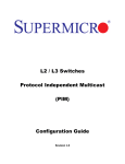
1.1.2 IPv6 Header
The IPv6 header format is similar to IPv4 header fields. Even though IPv6 addresses are four times longer
than IPv4 addresses, the IPv6 header is only twice the size of the IPv4 header.
The IPv6 packet header has 8 fields with a size of 40 octets (320 bits). Fragmentation is handled by the
source of a packet and checksums at the data link layer and transport layer.
Supermicro L2/L3 Switches Configuration Guide
7
Version
Traffic Class
Flow Label
Payload Length
Next Header
Hop Limit
Source Address
40 octets
Destination Address
Next Header
Extension Header Information
Variable
Length
Data Portion
32 bits
Figure IPv6-1: IPv6 Header Format
The IPv6 packet header fields are listed in the table below.
Field
Description
Version
Similar to the IPv4 packet header, except that the field lists number
6 for IPv6 instead of number 4 for IPv4.
Traffic Class Similar to the IPv4 packet header. The Traffic Class field tags packets
with a traffic class that is used in differentiated services.
Flow Label
New field in the IPv6 packet header. The Flow Label field tags
packets with a specific flow that differentiates the packets at the
network layer.
Payload
Similar to the Total Length field in the IPv4 packet header. The
Supermicro L2/L3 Switches Configuration Guide
8
Length
Payload Length field indicates the total length of the data portion of
the packet.
Next Header Similar to the IPv4 packet header. The value of the Next Header field
determines the type of information following the basic IPv6 header,
for example, a TCP or UDP packet or an Extension header.
Hop Limit
Similar to the Time to Live field in the IPv4 packet header. The value
of the Hop Limit field specifies the maximum number of routers that
an IPv6 packet can pass through before the packet is considered
invalid. Each router decrements the value by one. Because no
checksum is in the IPv6 header, the router can decrement the value
without needing to recalculate the checksum, which saves
processing resources.
Source
Address
Similar to the Source Address field in the IPv4 packet header, except
that this contains a 128-bit source address for IPv6.
Destination
Address
Similar to the Destination Address field in the IPv4 packet header,
except that the field contains a 128-bit destination address for IPv6.
Following the basic IPv6 packet header are optional extension headers and the data portion of the
packet. If present, each extension header is limited to 64 bits. There is no limit to the number of
extension headers in an IPv6 packet. Each extension header is identified by the Next Header field of the
previous header.
The extension header types and their Next Header field values are mentioned in the table below.
Header Type
Next
Header
Value
Description
Hop-by-hop
options
header
0
Header that is processed by all hops in the path of a
packet. If present, the hop-by-hop options header
always follows immediately after the basic IPv6 packet
header.
Destination
options
header
6
Header that can follow any hop-by-hop options header.
The header is processed at the final destination and at
each visited address specified by a routing header. The
destination options header is processed only at the
final destination.
Routing
header
43
Header that is used for source routing.
Fragment
header
44
Header that is used in each fragment, when a source
fragments a packet that is larger than the Maximum
Transmission Unit (MTU) for the path between itself
Supermicro L2/L3 Switches Configuration Guide
9
and a destination.
Upper-layer
headers
6 (TCP)
Headers inside a packet to transport the data. The two
main transport protocols are TCP and UDP.
17 (UDP)
1.1.3 IPv6 Tunnel
Because most networks use the IPv4 protocol, IPv6 networks currently require a way to communicate
outside their borders. IPv6 networks use tunnels for this purpose. In most IPv6 tunneling scenarios, the
outbound IPv6 packet is encapsulated inside an IPv4 packet. The boundary router of the IPv6 network
sets up a point-to-point tunnel over various IPv4 networks to the boundary router of the destination
IPv6 network. The packet travels over the tunnel to the destination network's boundary router, which
decapsulates the packet. Then, the router forwards the separate IPv6 packet to the destination node.
1.1.4 Neighbor Discovery Protocol
Neighbor Discovery permits nodes on the same link to advertise their existence to their neighbors and
to learn about the existence of their neighbors. Neighbor Discovery is built on top of Internet Control
Message Protocol version 6 (ICMPv6).
Neighbor Discovery uses router advertisement messages to detect neighbors, advertise IPv6 prefixes,
address provisioning, and share link parameters such as MTU, hop limit, advertisement intervals, and
lifetime.
Neighbor Discovery uses the following message types:
Router Advertisement (RA) —Messages sent to announce the presence of the router, advertise prefixes,
assist in address configuration, and share other link information such as MTU size and hop limit. The
IPv6 nodes on the link can use this information to configure themselves with an IPv6 address and
routing information such as the default gateway.
Router Solicitation (RS)—Messages sent by IPv6 nodes when they come online to solicit immediate
router advertisements from the router.
Neighbor Solicitation (NS)—Messages used for duplicate address detection and to test the reachability
of neighbors. A host can verify that its address is unique by sending a neighbor solicitation message
destined to the new address. If the host receives a neighbor advertisement in reply, the address is a
duplicate.
Neighbor Advertisement (NA)—Messages used for duplicate address detection and to test the
reachability of neighbors. Neighbor advertisements are sent in response to neighbor solicitation
messages.
Supermicro L2/L3 Switches Configuration Guide
10
Redirect – Routers use redirect messages to inform hosts of a better first hop for a destination, or that
the destination is on the same link.
1.1.4.1 Router Advertisement (RA)
Each router periodically sends to the multicast group a router advertisement packet that announces its
availability. This is applicable only on multicast-capable links and point-to-point links routers generate
router advertisements frequently so hosts learn of their neighbors within a few minutes.
Router advertisement messages also contain parameters such as the hop limit and link MTU. This
feature enables the centralized administration of critical parameters since parameters are set on routers
and propagated to all attached hosts.
1.1.4.2 Neighbor Solicitation
Neighbor solicitation messages determine if more than one node is assigned the same unicast address.
Neighbor unreachability detection detects the failure of a neighbor or the failure of the forward path to
the neighbor. This detection requires positive confirmation that the packets that are sent to a neighbor
are actually reaching that neighbor.
Neighbor unreachability detection uses confirmation from two sources: upper-layer protocols and
neighbor solicitation messages. When possible, upper-layer protocols provide a positive confirmation
that a connection is making forward progress. For example, when new TCP acknowledgments are
received, it is confirmed that previously sent data has been delivered correctly.
When a node does not receive positive confirmation from upper-layer protocols, the node sends unicast
neighbor solicitation messages. These messages solicit neighbor advertisements as reachability
confirmation from the next hop.
1.1.4.3 Duplicate Address Detection
Duplicate address detection is performed on a new link-local IPv6 address before the address is assigned
to an interface:
•
•
•
•
A node sends a neighbor solicitation message with an unspecified source address and a
tentative link-local address in the body of the message.
If another node is already using that address, the node returns a neighbor advertisement
message that contains the tentative link-local address.
If another node is simultaneously verifying the uniqueness of the same address, that node also
returns a neighbor solicitation message.
If no neighbor advertisement messages are received in response to the neighbor solicitation
message and no neighbor solicitation messages are received from the other nodes that are
attempting to verify the same tentative address, the node that sent the original neighbor
Supermicro L2/L3 Switches Configuration Guide
11
solicitation message considers the link-local address to be unique and assigns the address to the
interface.
1.1.4.4 RA Prefixes
Router advertisements contain subnet prefixes, which are used to determine if a host is on the same link
(on-link) as the router. Hosts use the advertised prefixes to build and maintain a list that is used to
decide when a packet's destination is on-link or beyond a router.
Router advertisements and per-prefix flags provide stateless address auto configuration.
1.1.4.5 Stateless Autoconfiguration
All interfaces on IPv6 nodes have a link-local address on startup, which is usually automatically
configured from the identifier for an interface and the link-local prefix FE80::/10. A link-local address
enables a node to communicate with other nodes on the link and can be used to further configure the
node.
Nodes can connect to a network and automatically generate global IPv6 addresses without the need for
manual configuration or the help of a server such as a Dynamic Host Configuration Protocol (DHCP)
server.
1.1.4.6 Timers
Supermicro switches enable the configuration of the following Neighbor Discovery timers:
•
Router Advertisement Interval
By default, router advertisements are sent out every 200 seconds. Supermicro allows user to
change the interval between router advertisement transmissions on an interface.
•
Neighbor Reachable Time
The neighbor reachable time enables the detection of unavailable neighbors. Shorter configured
times enable detecting unavailable neighbors more quickly, however, this consumes more
network bandwidth and processing resources in all IPv6 network devices. Very short configured
times are not recommended in normal IPv6 operations.
•
Router Lifetime
The router lifetime value specifies how long nodes on the local link should consider the switch as
the default router on the link.
Supermicro L2/L3 Switches Configuration Guide
12
•
Retransmit Time
The retransmission timer is used to control the time between retransmissions of neighbor
solicitation messages.
1.1.4.7 Hop Limit
The Hop Limit field specifies the maximum number of routers that an IPv6 packet can pass through
before the packet is considered invalid. Each router decrements the value by one. Because no checksum
is in the IPv6 header, the router can decrement the value without needing to recalculate the checksum,
which saves processing resources.
1.1.4.8 Static Neighbor
Supermicro provides manual configuration of a neighbor in the IPv6 neighbor cache. If an entry for the
specified IPv6 address already exists in the neighbor discovery cache (learned through the IPv6 neighbor
discovery process) the entry is automatically converted to a static entry. Static entries in the IPv6
neighbor discovery cache are not modified by the neighbor discovery process.
1.2 IPv6 Configuration
1.2.1 Default Configuration
Parameter
Default Value
IPv6 Status
Prefix Type
Global Unicast Address
Router Advertisement Status
Managed Config Flag
Other Config Flag
Hop Limit
DAD Attempt
Reachable Time
Retransmit Time
Router Advertisement Prefix
Router Advertisement Interval
IPv6 Neighbor
Router Advertisement Lifetime
RA Valid Lifetime
Ping Data
Ping Repeat Count
Ping Size
Ping Timeout
Disabled
Unicast
None
Suppressed
Disabled
Disabled
64
1
30
1
None
600
None
1800
259200
a5a5
5
100 bytes
5 seconds
Supermicro L2/L3 Switches Configuration Guide
13
1.2.2 Enabling IPv6
IPv6 processing is disabled by default in Supermicro switches. Follow the below steps to enable IPv6
processing on an interface.
Step
Command
Step 1
Step 2
configure terminal
Create a Layer 2 VLAN and add all required ports.
Step 3
Step 4
Step 5
Description
Enters the configuration mode
For details on configuring a Layer 2
VLAN, refer to the ‘VLAN Config. guide’
at www.supermicro.com
interface vlan<vlan-id (1-4069)>
Enters the interface configuration
mode to specify which interface to be
configured as a Layer 3 interface.
ipv6 enable
Enable IPv6 on the VLAN
ipv6 address <prefix> <prefix Len> [{unicast | Configures an IPv6 address to create a
anycast | eui64}]
Layer3 VLAN.
ipv6 address <prefix> link-local
Configures an IPv6 link-local address on
an interface.
prefix - IPv6 prefix for the interface
prefix-len - IPv6 prefix length
unicast - Unicast type of prefix
anycast - Anycast type of prefix
eui64 - Type of prefix where the latter
64 bits are formed from the MAC
address
link-local - Type of address.
Step 6
Step 7
End
show ipv6 interface [{vlan <id>
| tunnel <id> [prefix]]
The prefix length for an eui64 type
must be 64.
Exits the configuration mode.
Displays the IPv6 Layer3 VLAN interface
configuration.
The command “no ipv6 enable” disables IPv6 on a Layer3 VLAN interface.
The command “no ipv6 address <prefix> <prefix Len> [{unicast | anycast | eui64}]” deletes
Supermicro L2/L3 Switches Configuration Guide
14
the IPv6 address configured on an interface.
The command no “ipv6 address <prefix> link-local” deletes the IPv6 link-local address
configured on an interface.
1.2.3 Neighbor Discovery Protocol
Step
Command
Step 1
Step 2
configure terminal
ipv6 neighbor <prefix> {vlan <id>
| tunnel <id> <MAC ADDRESS (xx:xx:xx:xx:xx:xx)>
Create a Layer 2 VLAN and add all required ports.
Step 3
Step 4
Step 5
Step 6
Description
Enters the configuration mode
(Optional) Configures a static entry in
the IPv6 neighbor cache
For details on configuring a Layer 2
VLAN, refer to the ‘VLAN Config. guide’
at www.supermicro.com
interface vlan<vlan-id (1-4069)> | <interface- Enters the Layer 3 interface
type> <interface-id>
configuration mode.
NOTE: This command is also applicable
to VLANs and Routed Physical
Interfaces. Refer to ‘IP Config guide’ at
www.supermicro.com.
ipv6 enable
Enables IPv6 on the VLAN
ipv6 address <prefix> <prefix Len> [{unicast | Configures an IPv6 address to create a
anycast | eui64}]
Layer3 VLAN.
ipv6 address <prefix> link-local
Configures an IPv6 link-local address on
an interface.
prefix - IPv6 prefix for the interface
prefix-len - IPv6 prefix length
unicast - Unicast type of prefix
anycast - Anycast type of prefix
eui64 - Type of prefix where the latter
64 bits are formed from the MAC
address
link-local - Type of address.
The prefix length for an eui64 type
Supermicro L2/L3 Switches Configuration Guide
15
must be 64.
Enables an IPv6 router advertisement
Step 7
no ipv6 nd suppress-ra
Step 8
ipv6 nd managed-config flag
Step 9
ipv6 nd other-config flag
Step 10
ipv6 hop-limit <HopLimit (1-255)>
Step 11
ipv6 nd ra-lifetime <LifeTime (0-9000)>
Step 12
NOTE: The RA lifetime value must be
greater than or equal to the RA
interval.
ipv6 nd dad attempts <no of attempts (1-10)>
(Optional) Sets Duplicate Address
Detection attempts. Range is 1-10.
ipv6 nd reachable-time <Reachable Time (0- (Optional) Sets advertised reachability
3600)>
time. Range is 0-3600.
Step 13
Step 14
Step 15
Step 16
(Optional) Sets the managed-config
flag, which allows the host to use DHCP
for address configuration.
(Optional) Sets the other-config flag,
which allows the host to use DHCP for
other stateful configurations
(Optional) Configures maximum hop
limit for all IPv6 packets originating
from the interface. Range is 1-255.
(Optional) Sets the IPv6 Router
Advertisement (RA) lifetime. Range is 09000.
(Optional) Sets advertised retransmit
time. Range is 1-3600.
ipv6 nd ra-interval <interval (3-1800)>
Sets the Ipv6 router advertisement
interval
ipv6 nd prefix {<prefix addr> <prefixlen> | (Optional) Configures the prefix to be
default} [{{<valid lifetime> | infinite | at <var advertised in the IPv6 router
valid lifetime>}{<preferred lifetime> |infinite | at advertisement
<var preferred lifetime>} | no-advertise}] [offlink] [no-autoconfig]
prefix-addr - IPv6 prefix to be
advertised
ipv6 nd retrans-time <Retrans Time (1-3600)>
prefix-len - Length of the configured
prefix
default - Changes the default value of
the rest of the parameters.
valid-lifetime - Sets the valid lifetime
value for the prefix.
infinite - Sets the infinite valid lifetime
Supermicro L2/L3 Switches Configuration Guide
16
value for the prefix.
at - Sets the variable valid lifetime value
for the prefix.
preferred-lifetime - Sets the preferred
lifetime value for the prefix.
infinite - Sets the infinite preferred
lifetime value for the prefix.
at - Sets the variable valid lifetime value
for the prefix.
no-advertise - Sets the no-advertise
flag.
off-link - Sets the off-link flag.
no-autoconfig - Sets the no-autoconfig
flag.
Step 17
Step 18
End
show ipv6 interface [{vlan <id>
| tunnel <id> [prefix]]
Displays the IPv6 interface information.
show ipv6 route
Displays the IPv6 route information.
show ipv6 route summary
Displays the route summary for IPv6.
show ipv6 neighbors
Displays the IPv6 neighbors.
show ipv6 traffic
Displays ICMP & UDP packet statistics.
Step 19
clear ipv6 neighbors
Removes all entries in the IPv6
neighbor table. Neighbors may be
learned again via Neighbor Discovery.
Step 20
clear ipv6 traffic
Removes all the entries in the IPv6
traffic table.
The command “no ipv6 neighbor <prefix> {vlan <id> | tunnel <id> <MAC ADDRESS
xx:xx:xx:xx:xx:xx>” deletes static entries from the IPv6 neighbor cache table.
The command “ipv6 nd suppress-ra” suppresses router advertisements.
Supermicro L2/L3 Switches Configuration Guide
17
The command “no ipv6 nd managed-config flag” specifies that the host should NOT use
DHCP for address configurations.
The command “no ipv6 nd other-config flag” specifies that the host should NOT use DHCP
for other address configurations.
The command “no ipv6 hop-limit” resets the hop limit to its default value of 1 for all IPv6
packets originating from the interface.
The command “no ipv6 nd dad attempts” resets the duplicate address detection attempts
to its default value of 1.
The command “no ipv6 nd reachable-time” resets the advertised reachability time to its
default value of 30.
The command “no ipv6 nd retrans-time” resets the advertised retransmit time to its default
value of 1.
The command “no ipv6 nd ra-interval” resets the IPv6 router advertisement interval to its
default value of 600.
The command “no ipv6 nd prefix {<prefix addr> <prefix len> | default}” removes the prefix
from the IPv6 router advertisement.
1.2.4 Configuration Example
The example below shows the commands used to enable IPv6 between two switches – switch A and
switch B.
Configuration on switch A
SMIS# configure terminal
SMIS(config)# vlan 10
SMIS(config-vlan)# ports gi 0/21 untagged
SMIS(config-vlan)# exit
SMIS(config)# interface vlan 10
SMIS(config-if)# ipv6 enable
SMIS(config-if)# ipv6 address 3333::1111 64 unicast
SMIS(config-if)# end
SMIS# show ipv6 interface
vlan10 is up, line protocol is up
IPv6 is Enabled
Link local address:
fe80::230:48ff:fee3:475
Supermicro L2/L3 Switches Configuration Guide
18
Global unicast address(es):
3333::1111/64
Joined group address(es):
ff02::1
ff02::2
ff02::1:ff00:1111
ff02::1:ffe3:475
MTU is 1500
ICMP redirects are enabled
ND DAD is enabled, Number of DAD attempts: 1
ND router advertisement is disabled
SMIS# configure terminal
SMIS(config)# interface vlan 10
SMIS(config-if)# no ipv6 nd suppress-ra
SMIS(config-if)# ipv6 nd reachable-time 100
SMIS(config-if)# end
SMIS# show ipv6 neighbors
IPv6 Address
Age Link-layer Addr State
Interface
fe80::230:48ff:fee3:70bc
0 00:30:48:e3:70:bc Stale
vlan10
SMIS# show ipv6 interface
vlan10 is up, line protocol is up
IPv6 is Enabled
Link local address:
fe80::230:48ff:fee3:475
Global unicast address(es):
3333::1111/64
Joined group address(es):
ff02::1
ff02::2
ff02::1:ff00:1111
ff02::1:ffe3:475
MTU is 1500
ICMP redirects are enabled
ND DAD is enabled, Number of DAD attempts: 1
ND router advertisement is enabled
ND reachable time is 100 seconds
ND retransmit time is 1 seconds
ND router advertisements are sent every 600 seconds
SMIS# show ipv6 route
IPv6 Routing Table - 1 entries
Codes : C - Connected, S - Static
O - OSPF, R - RIP, B - BGP
Supermicro L2/L3 Switches Configuration Guide
19
C 3333::/64 [1/1]
via ::, vlan10
SMIS# show ipv6 route summary
IPv6 Routing Table Summary - 1 entries
1 Connected, 0 Static, 0 RIP, 0 BGP, 0 OSPF
Number of prefixes:
/64: 1
SMIS# show ipv6 traffic
IPv6 Statistics
***************
9 Rcvd
0 HdrErrors 0 TooBigErrors
0 AddrErrors 0 FwdDgrams 0 UnknownProtos
0 Discards 8 Delivers 8 OutRequests
0 OutDiscards 0 OutNoRoutes 0 ReasmReqds
0 ReasmOKs 0 ReasmFails
0 FragOKs
0 FragFails 0 FragCreates
9 RcvdMCastPkt 8 SentMcastPkts 0 TruncatedPkts
0 RcvdRedirects
0 SentRedirects
ICMP Statistics
***************
Received :
9 ICMPPkts 0 ICMPErrPkt
0 DestUnreach 0 TimeExcds
0 ParmProbs 0 PktTooBigMsg 0 ICMPEchoReq 0 ICMPEchoReps
3 RouterSols 5 RouterAdv
0 NeighSols 0 NeighAdv
0 Redirects 0 AdminProhib 0 ICMPBadCode
Sent
0 ICMPMsgs 0 ICMPErrMsgs 0 DstUnReach 0 TimeExcds
0 ParmProbs 0 PktTooBigs
0 EchoReq 0 EchoReply
0 RouterSols 6 RouterAdv
2 NeighSols 0 NeighborAdv
0 RedirectMsgs 0 AdminProhibMsgs
UDP statistics
**************
Received :
0 UDPDgrams 1 UDPNoPorts
0 UDPErrPkts
Sent :
0 UDPDgrams
SMIS# show running-config
Building configuration...
Switch ID
Hardware Version
0
SBM-GEM-X3S+ (B4-01)
Firmware Version
1.0.14-7
vlan 1
Supermicro L2/L3 Switches Configuration Guide
20
ports gi 0/1-20 untagged
ports gi 0/22-24 untagged
ports ex 0/1-3 untagged
exit
vlan 10
ports gi 0/21 untagged
exit
interface vlan 10
exit
interface vlan 10
ipv6 enable
no ipv6 nd suppress-ra
ipv6 nd reachable-time 100
ipv6 address 3333::1111 64 unicast
ipv6 address fe80::230:48ff:fee3:475 link-local
ipv6 nd prefix 3333:: 64
exit
Configuration on switch B
SMIS# configure terminal
SMIS(config)# vlan 10
SMIS(config-vlan)# ports gi 0/22 untagged
SMIS(config-vlan)# exit
SMIS(config)# interface vlan 10
SMIS(config-if)# ipv6 enable
SMIS(config-if)# ipv6 address 3333::1122 64 unicast
SMIS(config-if)# end
SMIS# show ipv6 interface
vlan10 is up, line protocol is up
IPv6 is Enabled
Link local address:
fe80::230:48ff:fee3:470
Global unicast address(es):
3333::1122/64
Joined group address(es):
ff02::1
ff02::2
ff02::1:ff00:1122
ff02::1:ffe3:470
MTU is 1500
ICMP redirects are enabled
ND DAD is enabled, Number of DAD attempts: 1
ND router advertisement is disabled
Supermicro L2/L3 Switches Configuration Guide
21
SMIS# configure terminal
SMIS(config)# interface vlan 10
SMIS(config-if)# no ipv6 nd suppress-ra
SMIS(config-if)# ipv6 nd reachable-time 100
SMIS(config-if)# end
SMIS# show ipv6 interface
vlan10 is up, line protocol is up
IPv6 is Enabled
Link local address:
fe80::230:48ff:fee3:70bc
Global unicast address(es):
3333::1122/64
Joined group address(es):
ff02::1
ff02::2
ff02::1:ff00:1122
ff02::1:ffe3:70bc
MTU is 1500
ICMP redirects are enabled
ND DAD is enabled, Number of DAD attempts: 1
ND router advertisement is enabled
ND reachable time is 100 seconds
ND retransmit time is 1 seconds
ND router advertisements are sent every 600 seconds
SMIS# show ipv6 neighbors
IPv6 Address
Age Link-layer Addr State
Interface
fe80::230:48ff:fee3:475
0 00:30:48:e3:04:75 Stale
vlan10
SMIS# show ipv6 route
IPv6 Routing Table - 1 entries
Codes : C - Connected, S - Static
O - OSPF, R - RIP, B - BGP
C 3333::/64 [1/1]
via ::, vlan10
SMIS# show ipv6 route summary
IPv6 Routing Table Summary - 1 entries
1 Connected, 0 Static, 0 RIP, 0 BGP, 0 OSPF
Number of prefixes:
/64: 1
SMIS# show ipv6 route summary
IPv6 Routing Table Summary - 1 entries
Supermicro L2/L3 Switches Configuration Guide
22
1 Connected, 0 Static, 0 RIP, 0 BGP, 0 OSPF
Number of prefixes:
/64: 1
SMIS# show ipv6 traffic
IPv6 Statistics
***************
9 Rcvd
0 HdrErrors 0 TooBigErrors
0 AddrErrors 0 FwdDgrams 0 UnknownProtos
0 Discards 8 Delivers 7 OutRequests
0 OutDiscards 0 OutNoRoutes 0 ReasmReqds
0 ReasmOKs 0 ReasmFails
0 FragOKs
0 FragFails 0 FragCreates
9 RcvdMCastPkt 7 SentMcastPkts 0 TruncatedPkts
0 RcvdRedirects
0 SentRedirects
ICMP Statistics
***************
Received :
9 ICMPPkts 0 ICMPErrPkt
0 DestUnreach 0 TimeExcds
0 ParmProbs 0 PktTooBigMsg 0 ICMPEchoReq 0 ICMPEchoReps
2 RouterSols 6 RouterAdv
0 NeighSols 0 NeighAdv
0 Redirects 0 AdminProhib 0 ICMPBadCode
Sent
0 ICMPMsgs 0 ICMPErrMsgs 0 DstUnReach 0 TimeExcds
0 ParmProbs 0 PktTooBigs
0 EchoReq 0 EchoReply
0 RouterSols 5 RouterAdv
2 NeighSols 0 NeighborAdv
0 RedirectMsgs 0 AdminProhibMsgs
UDP statistics
**************
Received :
0 UDPDgrams 1 UDPNoPorts
0 UDPErrPkts
Sent :
0 UDPDgrams
SMIS# show running-config
Building configuration...
Switch ID
Hardware Version
0
SBM-GEM-X3S+ (B4-01)
Firmware Version
1.0.14-7
vlan 1
ports gi 0/1-21 untagged
ports gi 0/23-24 untagged
ports ex 0/1-3 untagged
exit
vlan 10
Supermicro L2/L3 Switches Configuration Guide
23
ports gi 0/22 untagged
exit
interface vlan 10
exit
interface vlan 10
ipv6 enable
no ipv6 nd suppress-ra
ipv6 nd reachable-time 100
ipv6 address 3333::1122 64 unicast
ipv6 address fe80::230:48ff:fee3:70bc link-local
ipv6 nd prefix 3333:: 64
exit
1.3 IPv6 Unicast Routing
1.3.1 Default Configuration
Parameter
Default Value
IPv6 Unicast Routing Status
IPv6 Static Route
Administrative Distance
Enabled
None
1
1.3.2 Disable/Enable Unicast Routing
Step
Command
Description
Step 1
Step 2
Step 3
configure terminal
no ipv6 unicast-routing
End
Enters the configuration mode
Enables unicast routing
Exits the configuration mode.
The command “ipv6 unicast-routing” enables unicast routing.
Unicast routing should be enabled before configuring any unicast or multicast routing
protocol.
The example below shows the commands used to disable IPv6 unicast routing.
SMIS# configure terminal
Supermicro L2/L3 Switches Configuration Guide
24
SMIS(config)# no ipv6 unicast-routing
Ensure to disable all the ipv6 routing protocols
SMIS(config)# end
1.3.3 Static Route Configuration
Step
Command
Step 1
Step 2
configure terminal
Enters the configuration mode
ipv6 route <prefix> <prefix len> ([<NextHop>] Configures static routes
{[vlan <id>]}) [<administrative distance>]
[unicast]
prefix - IPv6 prefix of the destination
Description
prefix-len - Destination prefix length
next-hop - IPv6 prefix of the next hop
that is used to reach the destination
network.
vlan - VLAN identifier
administrative-distance - Metric to
reach the destination
Step 3
End
unicast - Unicast type of prefix
Exits the configuration mode.
The command “no ipv6 route <prefix> <prefix len> ([<NextHop>] {[vlan <id>]})
[<administrative distance>] [unicast]” deletes the static routes configured.
The next-hop for a static route should be a reachable interface on the switch.
The example below shows the commands used to configure an IPv6 static route.
SMIS# configure terminal
SMIS(config)# ipv6 route fec0::3333:0:0 96 fe80::230:48ff:fee3:475
SMIS(config)# end
SMIS# show ipv6 route
IPv6 Routing Table - 1 entries
Codes : C - Connected, S - Static
Supermicro L2/L3 Switches Configuration Guide
25
O - OSPF, R - RIP, B - BGP
C 3333::/64 [1/1]
via ::, vlan10
1.3.4 RIPng
Routing Information Protocol (RIP) is a distance-vector routing protocol that uses the hop count (the
number of routers) to determine the best way (shortest path) to a remote network. RIP sends the
complete routing table out to all active interfaces every 30 seconds.
RIP is a widely-used protocol for managing router information within a self-contained network such as a
corporate local area network (LAN) or an interconnected group of such LANs. RIP is considered an
effective solution for small homogeneous networks. It is not suited for larger, more complicated
networks since the transmission of the entire routing table every 30 seconds increases network traffic.
IPv6 RIP, known as RIP Next Generation (RIPng) functions the same as RIP in IPv4. RIP enhancements for
IPv6 includes
• support for IPv6 addresses and prefixes
• use of the all-RIP-routers multicast group address FF02::9 as the destination address for RIP
updates messages.
• IPv6 RIP process maintains a local routing table, referred to as a Routing Information Database
(RIB). The IPv6 RIP RIB contains a set of the best-cost IPv6 RIP routes learned from all its
neighboring networking devices. If IPv6 RIP learns the same route from two different neighbors
but with different costs, it will store only the lowest cost route in the local RIB.
1.3.4.1 Metric
RIP uses a single routing metric (hop count) to measure the distance between the source and a
destination network. Each hop in a path from source to destination is assigned a hop count value, which
is typically 1. When a router receives a routing update that contains a new or changed destination
network entry, the router adds 1 to the metric value indicated in the update and enters the network in
the routing table. RIP routing is limited to 15 hops. A metric of 16 hops identifies unreachable network.
1.3.4.2 Split Horizon
Routers connected to broadcast-type IP networks use the splithorizon mechanism to reduce routing
loops, especially when links are broken. A split horizon blocks information about routes from being
advertised by a router on any interface from which that information originated.
Supermicro switches support the following two mechanisms that help ensure the reachability of routes:
Supermicro L2/L3 Switches Configuration Guide
26
•
•
Split horizon: this mechanism omits routes learned from a neighbor in updates sent to that
neighbor. Split horizon minimizes routing overhead, but may cause slower convergence.
Split horizon with poison reverse: this mechanism includes routes learned from a neighbor in
updates sent to that neighbor. However, it sets the metric to 16 to which avoid looping. Poison
reverse speeds up convergence but increases routing overhead.
1.3.4.3 Passive Interface
Passive interfaces are used to suppress routing updates. These interfaces can be used to allow an
interface to receive updates but prevent the interface from sending advertisements.
1.3.4.4 RIPng Configuration
1.3.4.4.1 Default Configuration
Parameter
Default Value
RIPng Status
Split Horizon Status
Metric
Redistribution
Disabled
Enabled with Poison Reverse
10
Enabled
1.3.4.4.2 Enabling RIPng
RIP is disabled by default in Supermicro switches. Follow the below steps to enable RIP.
Step
Command
Description
Step 1
Step 2
configure terminal
ipv6 rip enable
Step 3
Step 4
show ipv6 rip
End
Enters the configuration mode
Enables RIP on all interfaces and enters
the router configuration mode
Display the RIP configuration.
Exits the configuration mode.
The “no ipv6 rip enable” command disables RIP in a switch.
Supermicro L2/L3 Switches Configuration Guide
27
1.3.4.4.3 Interface Parameters
Supermicro switches provide configuration of Interface parameters for RIP. Follow the below steps to
configure a RIP interface parameters.
Step
Command
Description
Step 1
Step 2
configure terminal
interface vlan <vlan-id>
Step 3
Step 4
ipv6 rip enable
ipv6 split-horizon [poison]
Step 5
ipv6 rip default-information originate
Step 6
ipv6 rip metric-offset <integer (1-15)>
Step 7
Step 8
End
show ipv6 rip {database}
Enters the configuration mode
(Optional)
Enters
the interface
configuration mode. This command is
applicable only for Layer3 VLAN
interfaces with an IPv6 address
configured.
Enables RIP routing
(Optional) Configures the split horizon
status
Configures the handling of the default
route origination
Adjusts the default metric increment.
Range is 1-15.
Exits the configuration mode.
Displays IPv6 local RIB and routing
protocol information
show ipv6 rip stats
Displays all the interface statistics.
show ipv6 rip filter
Displays the peer and Advfilter tables.
The command no ipv6 split-horizon Disable the split horizon status
The command “no ipv6 rip default-information“ disables the handling of the default route
originate.
1.3.4.4.4 Redistribution
Supermicro switches provide configuration of certain additional RIP parameters. Follow the below steps
to configure additional RIP parameters.
Step
Command
Description
Step 1
configure terminal
Step 2 redistribute {static|connected|ospf} metric
<integer(0-16)>
Enters the configuration mode
(Optional) Enables the redistribution of
corresponding protocol routes into
RIP.
connected - Connected routes
Supermicro L2/L3 Switches Configuration Guide
28
redistribution.
ospf - Advertises routes learned by
OSPF in the RIP process.
static - Statically configured routes to
advertise in the RIP process.
Step 3
distribute prefix <ip6_addr> {in | out}
Step 4
Step 5
End
show ipv6 rip {database}
Metric – Route metric in range of 0-16
(Optional) Enables filter network in
routing updates sent or received.
Exits the configuration mode.
Displays the IPv6 local RIB and routing
protocol information
show ipv6 rip stats
Displays all the interface statistics.
show ipv6 rip filter
Displays the peer and Advfilter table.
The command “no redistribute {static|connected|ospf}“ disables the redistribution of routes from
another protocol (Static or connected or OSPF) into RIP6.
The command “no distribute prefix <ip6_addr> {in | out}” disables the filter network in
routing updates sent or received.
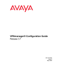
1.3.4.4.5 RIP Configuration Example
The example below shows the commands used to configure RIP by using two switches: switch A and
switch B.
Gi 0/21
Gi 0/22
Switch A
Switch B
Figure IPv6 -2: RIPng Configuration Example
Supermicro L2/L3 Switches Configuration Guide
29
The example below shows the commands used to enable IPv6 between two switches – switch A and
switch B.
Configuration on switch A
SMIS# configure terminal
SMIS(config)# vlan 10
SMIS(config-vlan)# ports gi 0/21 untagged
SMIS(config-vlan)# exit
SMIS(config)# interface vlan 10
SMIS(config-if)# ipv6 enable
SMIS(config-if)# ipv6 address 3333::1111 64 unicast
SMIS(config-if)# end
SMIS# show ipv6 interface
vlan10 is up, line protocol is up
IPv6 is Enabled
Link local address:
fe80::230:48ff:fee3:475
Global unicast address(es):
3333::1111/64
Joined group address(es):
ff02::1
ff02::2
ff02::1:ff00:1111
ff02::1:ffe3:475
MTU is 1500
ICMP redirects are enabled
ND DAD is enabled, Number of DAD attempts: 1
ND router advertisement is disabled
SMIS# configure terminal
SMIS(config)# ipv6 router rip
SMIS(config-router)# redistribute connected
SMIS(config-router)# end
SMIS# show ipv6 rip
RIP port 521, multicast-group ff02::9,Maximum paths is 16
Updates every 30 seconds; expire after 180
Garbage Collect after 120 seconds
Poison Reverse is on
Interface:
Redistribution:
Connected,Routes Redistribution is enabled.
SMIS# show ipv6 rip database
Supermicro L2/L3 Switches Configuration Guide
30
RIP local RIB
3333::/64, metric 1, local
vlan10/::, expires in 180 secs
SMIS# show running-config
Building configuration...
Switch ID
Hardware Version
0
SBM-GEM-X3S+ (B4-01)
Firmware Version
1.0.14-7
vlan 1
ports gi 0/1-20 untagged
ports gi 0/22-24 untagged
ports ex 0/1-3 untagged
exit
vlan 10
ports gi 0/21 untagged
exit
interface vlan 10
exit
interface vlan 10
ipv6 enable
ipv6 address 3333::1111 64 unicast
ipv6 address fe80::230:48ff:fee3:475 link-local
ipv6 nd prefix 3333:: 64
exit
ipv6 router rip
redistribute connected
exit
Configuration on switch B
SMIS# configure terminal
SMIS(config)# vlan 10
SMIS(config-vlan)# ports gi 0/22 untagged
SMIS(config-vlan)# exit
SMIS(config)# interface vlan 10
SMIS(config-if)# ipv6 enable
SMIS(config-if)# ipv6 address 3333::1122 64 unicast
SMIS(config-if)# end
SMIS# show ipv6 interface
Supermicro L2/L3 Switches Configuration Guide
31
vlan10 is up, line protocol is up
IPv6 is Enabled
Link local address:
fe80::230:48ff:fee3:470
Global unicast address(es):
3333::1122/64
Joined group address(es):
ff02::1
ff02::2
ff02::1:ff00:1122
ff02::1:ffe3:470
MTU is 1500
ICMP redirects are enabled
ND DAD is enabled, Number of DAD attempts: 1
ND router advertisement is disabled
SMIS# configure terminal
SMIS(config)# ipv6 router rip
SMIS(config-router)# redistribute connected
SMIS(config-router)# end
SMIS# show ipv6 rip
RIP port 521, multicast-group ff02::9,Maximum paths is 16
Updates every 30 seconds; expire after 180
Garbage Collect after 120 seconds
Poison Reverse is on
Interface:
Redistribution:
Connected,Routes Redistribution is enabled.
SMIS# show ipv6 rip database
RIP local RIB
3333::/64, metric 1, local
vlan10/::, expires in 180 secs
SMIS# show running-config
Building configuration...
Switch ID
Hardware Version
0
SBM-GEM-X3S+ (B4-01)
Firmware Version
1.0.14-7
vlan 1
ports gi 0/1-21 untagged
ports gi 0/23-24 untagged
Supermicro L2/L3 Switches Configuration Guide
32
ports ex 0/1-3 untagged
exit
vlan 10
ports gi 0/22 untagged
exit
interface vlan 10
exit
interface vlan 10
ipv6 enable
ipv6 address 3333::1122 64 unicast
ipv6 address fe80::230:48ff:fee3:470 link-local
ipv6 nd prefix 3333:: 64
exit
ipv6 router rip
redistribute connected
exit
1.3.5 OSPFv3
OSPFv3 adds support for IPv6 in the OSPF routing protocol. A hello packet is sent out on an OSPFenabled interface to discover other OSPFv3 neighbor routers. Once a neighbor is discovered, the two
routers compare information in the Hello packet to determine if they have compatible configurations.
Adjacent routers share link-state advertisements (LSAs) that include information about the operational
state of each link, the cost of the link, and any other neighbor information. When all OSPFv3 routers
have identical link-state databases, the network is said to be converged.
OSPFv3 networks can be divided into separate areas. Routers send most LSAs to one area only, which
reduces the CPU and memory requirements for an OSPF-enabled router.
1.3.5.1
Comparison of OSPFv3 and OSPFv2
Much of the OSPFv3 protocol is the same as in OSPFv2. OSPFv3 is described in RFC 2740.
The key differences between the OSPFv3 and OSPFv2 protocols are as follows:
• OSPFv3 expands on OSPFv2 to provide support for IPv6 routing prefixes and the larger size of IPv6
addresses.
•
LSAs in OSPFv3 are expressed as a prefix and prefix length instead of an address and mask.
•
The router ID and area ID are 32-bit numbers with no relationship to IPv6 addresses.
Supermicro L2/L3 Switches Configuration Guide
33
•
OSPFv3 uses link-local IPv6 addresses for neighbor discovery and other features.
•
OSPFv3 redefines LSA types.
1.3.5.2 Neighbor & DR
OSPF routers exchange hellos with neighboring routers and in the process learn their neighbor’s Router
ID (RID) and cost. These values are then stored in the adjacency table.
Supermicro switches establish OSPF adjacencies between all neighbors on a multi-access network (such
as Ethernet). This ensures all routers do not need to maintain full adjacencies with each other.
The Designated Router (DR) is selected based on the router priority. In a tie, the router with the highest
router ID is selected. A backup DR is a router designed to perform the same functions in case the DR
fails.
1.3.5.3 LSA
Once a router has exchanged hellos with its neighbors and captured router IDs and cost information, it
begins sending LSAs, or Link State Advertisements. The link state is the information shared between
directly connected routers. This information propagates throughout the network unchanged and is also
used to create a shortest path first (SPF) tree.
The OSPF standard defines a number of LSA types. Unlike distance vector protocols (for example RIP),
the OSPF does not actually send its routing table to other routers. Instead, it sends the LSA database and
derives the IP routing table from LSAs.
In order to avoid an LSA storm, each LSA has a sequence number that is incremented only if the LSA has
changed. Each LSA also has an age value that is set to zero by the originating switch and increased by
every switch during flooding.
The common types of LSA are
Type 1 – Router LSA, which contains router ID and link information.
Type 2 – Network LSA, which contains DR and broadcast segment details.
Type 3 – Network Summary LSA, which is originated by ABR only and contains metric and subnet
information.
Supermicro L2/L3 Switches Configuration Guide
34
Type 4 – ASBR Summary LSA, which is originated by ABR only and advertised to ASBR. Contains router
ID, mask and metric.
Type 5 – AS external LSA, which is originated by ASBR and contains external route and default route
information.
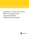
1.3.5.4 Area
An OSPF area is defined as a logical grouping of routers by a network administrator. OSPF routers in any
area contain same topological view, which is also known as the OSPF database of the network. OSPF is
configured in multiple areas in order to reduce routing table sizes, which in turn reduces the topological
database and switch CPU/memory requirements.
OSPF is not just configured in one large area, so all routers share the same topological database. The use
of multiple areas ensures that the flooding and database management required in large OSPF networks
is reduced within each area so that the process of flooding the full database and maintaining full
network connectivity does not consume a large portion of the CPU processing power and network
bandwidth. Every time a network change occurs, the CPU on a router is interrupted and a new OSPF tree
is calculated. Running the shortest path first (SPF) algorithm itself is not CPU intensive, but sending and
flooding the network with new topological information is extremely CPU intensive.
Areas are identified through a 32-bit area ID expressed in dotted decimal notation. All OSPF areas must
be connected to the backbone in case of network failure. When an area cannot reside physically or
logically on the backbone, a virtual link is required. There are four types of areas used in OSPF:
•
Backbone Area: alternate name for Area 0. This includes all the ABRs and internal routers of the
backbone area. The backbone is a hub for inter-area transit traffic and the distribution of routing
information between areas. Inter-area traffic is routed to the backbone, then routed to the
destination area, and finally routed to the destination host within the destination area. Routers
on the backbone also advertise the summarized routes within their areas to the other routers
on the backbone. The backbone area helps avoid routing loops as it is the trunk of the network.
•
Regular Area: non-backbone area, with both internal and external routes.
•
Stub area: an area that contains a single exit point. Areas that reside on the edge of the network
with no exit point except one path are termed a stub area.
Supermicro L2/L3 Switches Configuration Guide
35
•
Not-So-Stubby-Area (NSSA): This area is used to connect to an ISP. All advertised routes can be
flooded through the NSSA but are blocked by the ABR.
AREA 1
ABR and
Backbone
Routers
Internal
Router
AREA 0
AREA 0
Internet
Backbone
Routers
ASBR and
Backbone
Router
AREA 2
Internal Router
Figure IPv6- 3: OSPF Area
Internal Router
ABR and
Backbone
Routers
Supermicro L2/L3 Switches Configuration Guide
36
1.3.5.5 OSPF Router Types
There are different types of OSPF routers classified based on functionality.
•
Internal Router: this router is within a specific area only. Internal router functions include
maintaining the OSPF database and forwarding data to other networks. All interfaces on internal
routers are in the same area.
•
Backbone Router: backbone routers are connected to area 0, which is also represented as area
0.0.0.0. A backbone router can perform ASBR functions as well as ABR functions.
•
Area Border Router (ABR): ABRs are responsible for connecting two or more areas. An ABR
contains the full topological database for each area it is connected to and sends this information
to other areas. ABRs contain a separate Link State Database, separating LSA flooding between
areas, optionally summarizing routes, and optionally sourcing default routes.
•
Autonomous System Boundary Router (ASBR): this is a router that has at least one interface in an
OSPF area and at least one interface outside of an OSPF area. Routers that connect to, for
example, the Internet and redistribute external IP routing tables from such protocols as Border
Gateway Protocol (BGP) are termed autonomous system boundary routers (ASBRs).
1.3.5.6 Types of Routes
OSPF supports two types of routes: those through internal routers and those through external OSPFs.
External routes are routing entries in OSPF route tables injected by an external routing protocol, such as
BGP. When calculating the cost to a remote network, internal routes add the total cost to the
destination; whereas external routes include only the cost to the external network.
1.3.5.7 Default Route
When the redistribution of routes into an OSPF routing domain is configured, the route becomes an
autonomous system boundary router (ASBR). The ASBR can generate a default route into the OSPF
routing domain by user configuration.
1.3.5.8 Metric
The OSPF process assigns cost values to interfaces based on the inverse of the bandwidth parameter
assigned to the interface with the bandwidth command. For calculating the SPF to a given destination,
the router takes into consideration the costs of the links along various paths. The path with the lower
cost is selected as the shortest path. The SPF algorithm only runs within a single area, so routers only
compute paths within their own area. Inter-area routes are passed using border routers.
Supermicro L2/L3 Switches Configuration Guide
37
1.3.5.9 Router ID
The source of link state advertisements in a given area is identified by the router ID. This ID has the form
of an IP address and can be either automatically or manually defined.
1.3.5.10 Priority
In multi-access networks, the router with the highest priority value is chosen as the DR, which acts as
the central point of exchange for LSAs. Supermicro switches provide OSPF DR priority configuration.
1.3.5.11 Route Summarization
Route summarization is the consolidation of advertised addresses into a single summary route to be
advertised by other areas. Summarization occurs using the LSA type 4 packet or by the ASBR. OSPFs can
be configured in two ways to summarize networks:
•
Inter-area summarization creating type 3 or 4 LSAs
•
External summarization with type 5 LSAs
1.3.5.12 Timers
Supermicro switches provide configuration OSPFv3 timers:
• SPF Timer: the delay time between when OSPF receives a topology change and when it starts
the shortest path first (SPF) calculation and the hold time between two SPF calculations.
•
Hello Interval: specifies the interval between the hello packets sent on the interface. The hello
interval value must be the same for all routers attached to a common link.
•
Neighbor Probe Interval: specifies the time interval between consecutive neighbors probing.
•
Poll Interval: specifies an unsigned integer value reflecting the poll interval (that is, the larger
time interval, in seconds, between the hello packets sent to an inactive non-broadcast multiaccess neighbor). This value is much larger than the hello interval. The poll-interval does not
apply to point-to-multipoint interfaces.
1.3.5.13 Virtual Link
In OSPF, all areas must be connected to a backbone area. A virtual link can be configured in case of a
backbone-continuity break by configuring two area border routers as endpoints of a virtual link.
Configuration information includes the identity of the other virtual endpoint (the other ABR) and the
Supermicro L2/L3 Switches Configuration Guide
38
non-backbone link that the two routers have in common (the transit area). Virtual links cannot be
configured through a stub area.
1.3.5.14 Passive Interface
The passive-interface command disables OSPF hellos from being sent out, thus disabling the interface
from forming adjacencies on that interface.
1.3.5.15 Demand Circuit
A demand circuit is a point-to-point connection between two neighboring interfaces configured for the
OSPF. Demand circuits increase the efficiency of OSPFs on the configured interfaces by stopping the
periodic transmission of such OSPF packets as hello and LSA. OSPFs can establish a demand link to form
an adjacency and perform initial database synchronization. The adjacency remains active even after
layer 2 of the demand circuit goes down.
1.3.5.16 Network Type
Internet network types are dependent on the layer 2 technology used such as Ethernet, point-to-point
T1 circuit, and frame relay. The various OSPF network types and their compatibility with one another are
specified below.
Non-Broadcast: This is the default for OSPF-enabled frame relay physical interfaces. Non-broadcast
networks require a static neighbor configuration and OSPF hellos are sent via unicast. The nonbroadcast network type has a 30 second hello and a 120 second dead timer. An OSPF non-broadcast
network type requires the use of a DR/BDR.
Broadcast: This is the default for an OSPF-enabled Ethernet interface. The broadcast network type
requires link support layer 2 broadcast capabilities. The broadcast network type has a 10 second hello
and a 40 second dead timer. An OSPF broadcast network type requires the use of a DR/BDR.
Point-to-Point: A point-to-point OSPF network type does not maintain a DR/BDR relationship. The pointto-point network type has a 10 second hello and a 40 second dead timer. Point-to-point network types
are intended to be used between two directly connected routers.
Point-to-Multipoint: This is viewed as a collection of point-to-point links. Point-to-multipoint networks
do not maintain a DR/BDR relationship or advertise a hot route for all the frame-relay endpoints. The
point-to-multipoint network type has a 30 second hello and a 120 second dead timer.
Supermicro L2/L3 Switches Configuration Guide
39
1.3.5.17 OSPFv3 Configuration
1.3.5.17.1 Default Configuration
Parameter
Default Value
OSPFv3 Status
Router ID
Area
Hello Interval
Router Dead Interval
Transmit Delay
Router Priority
Retransmission Interval
Polling Interval
Passive Interface Status
Secondary IP
ASBR Status
NSSA ASBR Status
RPF 1583 Compatibility
LSA Interval
SPF Hold time
SPF Interval
ABR
Network Type
Metric
Disabled
None
None
10 seconds
40
1
1
5
120
Disabled
Disabled
Disabled
Disabled
Enabled
5
10 milliseconds
1 milliseconds
Standard ABR
Broadcast
10
1.3.5.17.2 Enabling OSPF
OSPF is disabled by default in Supermicro switches. Follow the steps below to enable OSPF and
configure an OSPF router ID.
Step
Command
Description
Step 1
Step 2
configure terminal
ipv6 router ospf
Enters the configuration mode
Enables the OSPF routing process.
Step 3
router-id <IPv4-Address>
Configures the router ID using an IPv4
address.
NOTE: Both OSPFv3 and OSPFv2 use a
32-bit IPv4 address to select the router
ID for an OSPF process.
Supermicro L2/L3 Switches Configuration Guide
40
Step 4
Step 5
Exits the configuration mode.
Displays general information about the
OSPFv3 routing process.
End
show ipv6 ospf info
The “no ipv6 router ospf” command disables OSPFv3 in the switch.
1.3.5.17.3 Area Parameters
Supermicro switches provide configuration options for the OSPF area. Follow the steps below to
configure the OSPF area and its parameters.
Step
Command
Description
Step 1
Step 2
configure terminal
ipv6 router ospf
Enters the configuration mode
Enables the OSPF routing process
Step 3
router-id <IPv4-Address>
Configures the router ID
Step 4
area <area-id> { { stub | nssa } [no-summary] }
Defines an area as either a stub area or
an nssa area
area-id - a 32-bit integer
stub - stub area
nssa – NSSA
Step 5
area <area-id> stability-interval <interval-value>
no-summary - allows an area to be a
stubby/not-so-stubby area but does not
allow summary routes to be injected
into it.
Configures the stability interval for the
NSSA area.
area-id - a 32-bit integer
stability-interval - the number of
seconds after which an elected
translator determines that its services
are no longer required and that it must
continue to perform its translation
duties.
Supermicro L2/L3 Switches Configuration Guide
41
Step 6
area <area-id> translation-role { always |
candidate }
Configures the translation role for the
NSSA area.
area-id - a 32-bit integer
translation-role - an NSSA border
router's ability to perform NSSA
Step 7
timers spf <spf-delay> <spf-holdtime>
To configure the SPF delay and SPF
Holdtime when an OSPF receives a
topology change and when it starts a
shortest path first (SPF) calculation, and
the hold time between two consecutive
SPF calculations.
spf-delay - The interval by which the
SPF calculation is delayed after a
topology change reception. The range is
1-65535.
spf-holdtime - The delay between two
consecutive SPF calculations. The range
is 1-65535.
Step 8
Sets the alternative ABR type.
abr-type { standard | cisco | ibm }
standard - standard ABR type
cisco - CISCO ABR type
Step 9
Step 10
area <area-id> default-metric <metric>
area <area-id> default-metric type <metricType>
ibm - IBM ABR type
Sets the default metric value for an
NSS/stub area type only.
default-metric - cost for the default
summary route in a NSS/stub area
Sets the default metric-type for an
NSS/stub area type only.
area-id - A 32 bit integer
Step 11
area <area-id> virtual-link <router-id> <if-index>
[hello-interval <seconds>] [retransmit-interval
<seconds>] [transmit-delay <seconds>] [deadinterval <seconds>]
default-metric type - Type of metric
Sets the virtual link between areas
area-id - a 32-bit integer
Supermicro L2/L3 Switches Configuration Guide
42
virtual-link - the router ID of the virtual
neighbor
if-index - interface index assigned to
the OSPFv3 virtual interface
hello-interval - the interval between
hello packets on the OSPFv3 virtual link
interface. Range is 1-65535.
Retransmit interval - the time between
link-state
advertisement
(LSA)
retransmissions
for
adjacencies
belonging to the OSPFv3 virtual link
interface. Range is 1-1800.
transmit-delay - the estimated time it
takes to transmit a link state update
packet over this interface. Range is 11800.
Step 12
Step 13
dead-interval - the interval at which
hello packets must not be seen before
its neighbors declare the router down.
Range is 1-65535.
Configures the router as an ASBR
ASBR Router
area <Area-ID> range <IPv6-Prefix> <PrefixLength> [{ advertise | not-advertise }] {summary
| Type7} [tag <tag-value>]
Only when ASBR (Autonomous System
Border Router) status is set to enabled
are routes from other protocols
redistributed into the OSPFv3 domain.
Summarizes routes at an area boundary
Area-ID - a 32-bit integer
range - internal aggregation address
range
IPv6-Prefix - the IPv6 address prefix of
the range
Prefix-Length - the prefix length of the
address range
advertise - flushes out all the routes
(LSAs) falling in the range and
Supermicro L2/L3 Switches Configuration Guide
43
generates an aggregated LSA for the
range
not-advertise - suppresses routes that
match the prefix/prefix-length pair
summary - summary LSA
Type7 - type-7 LSA
Step 14
area <AreaID> summary-prefix <IPv6-Prefix>
<Prefix-Length> [{ allowAll | denyAll | advertise |
not-advertise}] [Translation { enabled | disabled
}]
tag - sets the tag value for the
aggregated route
Sets the external summary address
AreaID - a 32-bit integer
summary-prefix - summary prefix
IPv6-Prefix - the IPv6 address prefix of
the range
Prefix-Length - the prefix length of the
address range
allowAll - when set to allowAll and the
associated AreaID is 0.0.0.0, aggregated
type-5 LSAs are generated for the
specified range. In addition, aggregated
type-7 LSAs are generated in all
the attached NSSAs for the specified
range.
denyAll - when set to denyAll, neither
Type-5 nor type-7 LSAs are generated
for the specified range.
advertise - when set to advertise and
the associated areaId is 0.0.0.0,
aggregated type-5 LSAs are generated.
Otherwise, if the associated AreaID is
x.x.x.x (other than 0.0.0.0) then an
aggregated type-7 LSA is generated in
NSSA area x.x.x.x.
not-advertise
when
set
to
doNotAdvertise and the associated
areaId is 0.0.0.0, a type-5 LSA is not
Supermicro L2/L3 Switches Configuration Guide
44
generated for the specified range, while
all the NSSA LSAs within this range are
flushed out and an aggregated type-7
LSA is generated in all attached NSSAs.
If the associated AreaIDis x.x.x.x (other
than 0.0.0.0), a type-7 LSA is not
generated in NSSA x.x.x.x for the
specified range.
Step 15
redistribute {static | connected | ripng | bgp}
Translation - when set to enabled, the
P-Bit is set in the generated type-7 LSA.
When set to disabled, the P-Bit is
cleared in the generated type-7 LSA for
the range.
Configures the protocol from which the
routes have to be redistributed into
OSPFv3.
static - advertises routes configured
statically in the OSPFv3 routing process
connected - advertises
directly
connected network routes in the
OSPFv3 routing process
ripng - advertises routes that are
learned by the RIP process in the
OSPFv3 routing process
Step 16
passive-interface
Step 17
host <IPv6-Address> {metric <cost>} [area-id
{<AreaID>}]
bgp - advertises routes that are learned
by the BGP process in the OSPFv3
routing process
Configures all the interfaces created
after this to be passive.
Configures a host entry with metric
and/or area-id
IPv6-Address - IPV6 address prefix
metric - metric to be advertised
Step 18
nssaAsbrDfRtTrans
Step 19
redist-config <IPv6-Prefix> <Prefix-Length>
area-id - a 32-bit integer
Enables the setting of the P bit in the
default type 7 LSA generated by an
NSSA internal ASBR
Configures the information to be
Supermicro L2/L3 Switches Configuration Guide
45
[metric-value <metric>] [metric-type {asExttype1
| asExttype2}] [tag <tag-value>]
applied to routes learned from RTM
IPv6-Prefix - the IPv6 address prefix
Prefix-Length - the prefix length of the
address
metric-value - the metric value applied
to the route before it is advertised to
the OSPFv3 domain
metric-type - the metric type applied to
the route before it is advertised to the
OSPFv3 domain
Step 20
as-external lsdb-limit <lsdb-limit (-1 - 0x7fffffff)>
Step 21
exit-overflow-interval <interval>
Step 22
demand-extensions
Step 23
reference-bandwidth <ref-bw>
Step 24
Step 25
End
show ipv6 ospf interface [ vlan <vlan-id(1-4069)>]
tag - the tag type describes whether
tags will be automatically generated or
will be manually configured
Sets to the maximum number of nondefault, AS-external LSAs entries that
can be stored in the link-state
database. If the value is -1, then there is
no limit.
Sets the number of seconds that, after
entering an overflow state, a router will
attempt to leave the overflow state.
Range is 1-65535.
Enables routing support for demand
routing.
Reference bandwidth in kilobits/second
for calculating default inteface metrics.
Range is 1-65535.
Exits the configuration mode.
Displays the OSPFv3-related interface
information
show ipv6 ospf neighbor [ <Neighbor-RouterID> ]
Displays OSPFv3 neighbors information
show ipv6 ospf { request-list | retrans-list } [
<Neighbor-RouterID> ]
Displays a list of all link state
advertisements (LSAs) in a request-list
or a retransmission-list
show ipv6 ospf virtual-links
Displays the parameters and the
current state of OSPFv3 virtual links
show ipv6 ospf border-routers
Displays the internal OSPFv3 routing
Supermicro L2/L3 Switches Configuration Guide
46
table entries to an ABR/ASBR
show ipv6 ospf { area-range | summary-prefix }
Displays summary address information
show ipv6 ospf info
Displays general information about the
OSPFv3 routing process
show ipv6 ospf [area <AreaID>] database
[{router|network|as-external|inter-prefix|interrouter|intra-prefix|link|nssa}] [{detail|HEX}]
Displays the LSA information
show ipv6 ospf route
Displays the routes learned by the
OSPFv3 process
show ipv6 ospf areas
Display the area table
show ipv6 ospf host
Display the host table information
show ipv6 ospf redist-config
Display the configuration information
to be applied to the routes learned
from the RTM
The command “no area <area-id> stability-interval“ sets the default value of the stability
interval for the NSSA area.
The command “no area <area-id> translation-role” configures the default translation role
for the NSSA area.
The command “no timers spf“ sets the default values for the spf-delay and spf-holdtime.
The command “no abr-type” sets the default ABR type to ‘Standard ABR’.
The command “no ASBR Router“ disables the ASBR status of the router.
The command “no redistribute {static | connected | ripng | bgp }” disables the
redistribution of routes from the given protocol to OSPFv3.
The command “no passive-interface” configures all subsequently created interfaces to be
non-passive.
The command “no host <IPv6-Address>” deletes a host entry.
The command “no area <area-id> [ { stub | nssa | virtual-link <router-id> | default-metric |
{range {summary | Type7} | summary-prefix} <IPv6-Prefix> <Prefix-Length>} ]” deletes an
Supermicro L2/L3 Switches Configuration Guide
47
area, converts a stub/nssa area to a normal area, deletes a virtual link, deletes a stub cost or
deletes an area-range or summary-prefix.
The command “no nssaAsbrDfRtTrans“ disables the setting of the P bit in a default type 7
LSA generated by an NSSA internal ASBR.
The command “no redist-config <IPv6-Prefix> <Prefix-Length>” deletes the information
applied to routes learned from an RTM.
The command “no demand-extensions” disables the routing support for demand routing.
1.3.5.17.4 Interface Parameters
All OSPF interface level configurations are optional and must be consistent/compatible across all routers
in an attached network. Follow the steps below to configure OSPF parameters in Supermicro switches.
Step
Command
Description
Step 1
Step 2
configure terminal
ipv6 router ospf
Enters the configuration mode
Enables the OSPF routing process
Step 3
router-id <IPv4-Address>
Configures the router ID
Step 4
Step 5
Exit
interface vlan <vlan-id>
Step 6
ipv6 ospf area <IPv4-Address>
Step 7
ipv6 ospf neighbor <IPv6-Address> [priority
<Number>]
Step 8
ipv6 ospf neighbor-probe retransmit-limit
<retrans-limit>
Step 9
ipv6 ospf demand-circuit
Step 10
ipv6 ospf retransmit-interval <interval>
Exits the router configuration mode.
(Optional)
Enters
the
interface
configuration mode. This command is
applicable only for layer3 VLAN
interfaces with an IPv6 address
configured.
To enable OSPFv3 for IPv6 on an
interface
To
configure
OSPFv3
routers
interconnected
to
nonbroadcast
networks.
Pre-requisites
for
neighbor
establishment:
• Demand circuit should be
disabled
• Network type should be pointto-point
Sets the number of consecutive LSA
retransmissions before the neighbor is
deemed inactive
Configures OSPF to treat the interface
as an OSPF demand circuit
Specifies the time between link-state
Supermicro L2/L3 Switches Configuration Guide
48
Step 11
ipv6 ospf transmit-delay <delay>
Step 12
ipv6 ospf priority <priority>
Step 13
ipv6 ospf hello-interval <interval>
Step 14
ipv6 ospf dead-interval <interval>
Step 15
ipv6 ospf metric <metric>
Step 16
ipv6 ospf network { broadcast | non-broadcast |
point-to-multipoint | point-to-point }
Step 17
ipv6 ospf poll-interval <interval>
advertisement (LSA) retransmissions for
adjacencies belonging to the interface.
Range is 1-65535.
(Optional) Configures the estimated
time it takes to transmit a link state
update packet on the interface. Range
is 1-1800.
(Optional) Configures the router
priority. Range is 1-255.
(Optional) Specifies the interval
between the hello packets sent on the
interface. Range is 1-65535.
(Optional) Configures the interval in
which hello packets must not be seen
before neighbors declare the router
down. Range is 1-65535.
(Optional) Explicitly specifies the cost of
sending a packet on an interface. Range
is 1-65535.
(Optional) Configures the OSPF network
type to a type other than the default for
a given media.
Configure the Poll Interval.
Interval – Poll Interval in seconds in range
1-65535. This value should be larger than
hello interval.
If hello packets are not received from a
neighbor switch, for the Router Dead
Interval period, hello packets are still sent
to the dead neighbor at a reduced rate
called Poll Interval.
Step 18
ipv6 ospf passive-interface
Step 19
ipv6 ospf neighbor probing
Step 19
Step 20
End
show ipv6 ospf interface [ vlan <vlan-id(14069)>]
Configures an OSPFv3 interface to be
passive
This command enables neighbor
probing on a demand-circuit enabled
interface.
Exits the configuration mode.
Displays OSPF interface information
show ipv6 ospf neighbor [ <Neighbor-RouterID> Displays OSPF neighbor.
]
show ip ospf retransmission-list [<neighbor-id>] Displays OSPF link state retransmission
Supermicro L2/L3 Switches Configuration Guide
49
[{ vlan <vlan-id (1-4069)> | <interface-type> list information
<interface-id> }]
show ip ospf info
Displays general information about the
OSPF routing process
The command “no ipv6 ospf” disables the OSPFv3 routing protocol on an interface.
The command “no ipv6 ospf demand-circuit” disables the demand circuit on an interface.
The command “no ipv6 ospf retransmit-interval” sets the default retransmit interval 5 for
an interface.
The command “no ipv6 ospf transmit-delay“ sets the default value of the transmit delay 1
for an interface.
The command “no ipv6 ospf priority” sets the default router priority 1 for an interface.
The command “no ipv6 ospf hello-interval” sets the default hello interval 10 for an
interface.
The command “no ipv6 ospf dead-interval” sets the default dead interval 40 for an
interface.
The command “no ipv6 ospf poll-interval” sets the default poll interval 120 for an interface.
The command “no ipv6 ospf metric” sets the default value 10 for the interface metric.
The command “no ipv6 ospf network“ sets the default value ‘broadcast’ for the network
type.
The command “no ipv6 ospf neighbor <IPv6-Address> [priority]” deletes the OSPFv3
neighbor.
The command “no ipv6 ospf passive-interface” configures an OSPFv3 interface to be nonpassive.
The command “no ipv6 ospf neighbor probing” disables neighbor probing on a demandcircuit enabled interface.
The command “no ipv6 ospf neighbor-probe retransmit-limit” sets to the default neighbor
probe retransmission limit.
Supermicro L2/L3 Switches Configuration Guide
50
1.3.5.17.5 OSPF Configuration Example
The example below shows the commands used to configure OSPF by connecting 2 switches: switch A
and switch B.
Gi 0/21
Gi 0/22
Switch A
Switch B
Figure IPv6-4: OSPFv3 Configuration Example
On Switch A
SMIS# configure terminal
SMIS(config)# interface vlan 10
SMIS(config-if)# ipv6 ospf neighbor fe80::230:48ff:fee3:470
SMIS(config-if)# ipv6 ospf area 0.0.0.0
SMIS(config-if)# ipv6 ospf network point-to-point
SMIS(config-if)# no ipv6 ospf demand-circuit
SMIS(config-if)# ipv6 ospf metric 100
SMIS(config-if)# exit
SMIS(config)# ipv6 router ospf
SMIS(config-router)# demand-extensions
SMIS(config-router)# asbr router
SMIS(config-router)# redistribute connected
SMIS(config-router)# end
SMIS# show ipv6 ospf neighbor
ID
Pri State
DeadTime
10.10.10.2 1
FULL/PTOP
32
Address
fe80::230:48ff:fee3:470
SMIS# show ipv6 ospf info
Router Id: 10.10.10.1
ABR Type: Standard ABR
SPF schedule delay: 5 secs Hold time between two SPFs: 10 secs
Exit Overflow Interval: 0
Ref BW: 100000
Ext Lsdb Limit: -1
Trace Value: 0x00000800
As Scope Lsa: 2
Checksum Sum: 0xb3cb
Demand Circuit: Enable
Passive Interface: Disable
Supermicro L2/L3 Switches Configuration Guide
51
Nssa Asbr Default Route Translation: Disable
Autonomous System Boundary Router
Number of Areas in this router 1
Area 0.0.0.0
Number of interfaces in this area is 1
Number of Area Scope Lsa: 4 Checksum Sum: 0x1ce90
Number of Indication Lsa: 0 SPF algorithm executed: 13 times
SMIS# show ipv6 ospf areas
OSPFV3 AREA CONFIGURATION INFORMATION
AreaId: 0.0.0.0
Area Type: NORMAL AREA
Spf Calculation: 13 (times) Area Bdr Rtr Count: 0
As Bdr Rtr Count: 1
Area Summary: Send Summary
SMIS# show ipv6 ospf route
OSPFV3 Process Routing Table
Dest/Prefix-Length
NextHop/IfIndex
Cost Rt.Type Area
3333::
/64
::
/vlan10 100 intraArea 0.0.0.0
SMIS# show ipv6 ospf interface
Ospfv3 Interface Information
Interface Name: vlan10 Interface Id: 504 Area Id: 0.0.0.0
Local Address: fe80::230:48ff:fee3:475
Router Id: 10.10.10.1
Network Type: PTOP
Cost: 100
State: PTOP
Designated Router Id: 0.0.0.0
local address: (null)
Backup Designated Router Id: 0.0.0.0
local address: (null)
Transmit Delay: 1 sec
Priority: 1
IfOptions: 0x0
Timer intervals configured:
Hello: 10, Dead: 40, Retransmit: 5, Poll: 120
Demand Circuit: Disable
Neighbor Probing: Disable
Nbr Probe Retrans Limit: 10
Nbr Probe Interval: 120
Hello due in 5 sec
Neighbor Count is: 1
Adjacent with neighbor 10.10.10.2
SMIS# show ipv6 ospf border-routers
OSPFv3 Process Border Router Information
Supermicro L2/L3 Switches Configuration Guide
52
Destination Type
NextHop
Cost Rt Type Area Id
10.10.10.2 ASBR fe80::230:48ff:fee3:470 100 intraArea 0.0.0.0
SMIS# write startup-config
Building configuration, Please wait. May take a few minutes ...
[OK]
SMIS# show running-config
Building configuration...
Switch ID
Hardware Version
0
SBM-GEM-X3S+ (B4-01)
Firmware Version
1.0.14-7
vlan 1
ports gi 0/1-20 untagged
ports gi 0/22-24 untagged
ports ex 0/1-3 untagged
exit
vlan 10
ports gi 0/21 untagged
exit
interface vlan 10
ip address 10.10.10.1 255.0.0.0
exit
interface vlan 10
ipv6 enable
ipv6 address 3333::1111 64 unicast
ipv6 address fe80::230:48ff:fee3:475 link-local
ipv6 nd prefix 3333:: 64
exit
ipv6 router ospf
router-id 10.10.10.1
ASBR Router
redistribute connected
exit
interface vlan 10
ipv6 ospf area 0.0.0.0
ipv6 ospf metric 100
ipv6 ospf network point-to-point
exit
Supermicro L2/L3 Switches Configuration Guide
53
On Switch B
SMIS# configure terminal
SMIS(config)# interface vlan 10
SMIS(config-if)# ipv6 ospf neighbor fe80::230:48ff:fee3:475
SMIS(config-if)# ipv6 ospf area 0.0.0.0
SMIS(config-if)# ipv6 ospf network point-to-point
SMIS(config-if)# no ipv6 ospf demand-circuit
SMIS(config-if)# ipv6 ospf metric 100
SMIS(config-if)# ipv6 ospf metric 200
SMIS(config-if)# ipv6 ospf transmit-delay 10
SMIS(config-if)# exit
SMIS(config)# ipv6 router ospf
SMIS(config-router)# demand-extensions
SMIS(config-router)# asbr router
SMIS(config-router)# redistribute connected
SMIS(config-router)# end
SMIS# show ipv6 ospf info
Router Id: 10.10.10.2
ABR Type: Standard ABR
SPF schedule delay: 5 secs Hold time between two SPFs: 10 secs
Exit Overflow Interval: 0
Ref BW: 100000
Ext Lsdb Limit: -1
Trace Value: 0x00000800
As Scope Lsa: 0
Checksum Sum: 0x0
Demand Circuit: Enable
Passive Interface: Disable
Nssa Asbr Default Route Translation: Disable
Number of Areas in this router 1
Area 0.0.0.0
Number of interfaces in this area is 1
Number of Area Scope Lsa: 1 Checksum Sum: 0x47d6
Number of Indication Lsa: 0 SPF algorithm executed: 0 times
SMIS# show ipv6 ospf neighbor
ID
Pri State
DeadTime
10.10.10.1 1
FULL/PTOP
35
Address
fe80::230:48ff:fee3:475
SMIS# show ipv6 ospf route
OSPFV3 Process Routing Table
Dest/Prefix-Length
NextHop/IfIndex
Cost Rt.Type Area
3333::
/64
::
/vlan10 200 intraArea 0.0.0.0
SMIS# show ipv6 ospf interface
Supermicro L2/L3 Switches Configuration Guide
54
OSPFv3 Interface Information
Interface Name: vlan10 Interface Id: 504 Area Id: 0.0.0.0
Local Address: fe80::230:48ff:fee3:470
Router Id: 10.10.10.2
Network Type: PTOP
Cost: 200
State: PTOP
Designated Router Id: 0.0.0.0
local address: (null)
Backup Designated Router Id: 0.0.0.0
local address: (null)
Transmit Delay: 10 sec
Priority: 1
IfOptions: 0x0
Timer intervals configured:
Hello: 10, Dead: 40, Retransmit: 5, Poll: 120
Demand Circuit: Disable
Neighbor Probing: Disable
Nbr Probe Retrans Limit: 10
Nbr Probe Interval: 120
Hello due in 4 sec
Neighbor Count is: 1
Adjacent with neighbor 10.10.10.1
SMIS# show ipv6 ospf areas
OSPFV3 AREA CONFIGURATION INFORMATION
AreaId: 0.0.0.0
Area Type: NORMAL AREA
Spf Calculation: 12 (times) Area Bdr Rtr Count: 0
As Bdr Rtr Count: 1
Area Summary: Send Summary
SMIS# show ipv6 ospf border-routers
OSPFv3 Process Border Router Information
Destination Type
NextHop
Cost Rt Type Area Id
10.10.10.1 ASBR fe80::230:48ff:fee3:475 200 intraArea 0.0.0.0
SMIS# write startup-config
Building configuration, Please wait. May take a few minutes ...
[OK]
SMIS# show running-config
Building configuration...
Switch ID
Hardware Version
0
SBM-GEM-X3S+ (B4-01)
Firmware Version
1.0.14-7
vlan 1
ports gi 0/1-21 untagged
ports gi 0/23-24 untagged
ports ex 0/1-3 untagged
exit
Supermicro L2/L3 Switches Configuration Guide
55
vlan 10
ports gi 0/22 untagged
exit
interface vlan 10
ip address 10.10.10.2 255.0.0.0
exit
interface vlan 10
ipv6 enable
ipv6 address 3333::1122 64 unicast
ipv6 address fe80::230:48ff:fee3:470 link-local
ipv6 nd prefix 3333:: 64
exit
ipv6 router ospf
router-id 10.10.10.2
ASBR Router
redistribute connected
exit
interface vlan 10
ipv6 ospf area 0.0.0.0
ipv6 ospf transmit-delay 10
ipv6 ospf metric 200
ipv6 ospf network point-to-point
exit
1.4 IP Multicast
IP communication may be one of three types:
•
•
•
Unicast: host sends packets to a single host.
Broadcast: host sends packets to all hosts.
Multicast: host sends packets to a subset of hosts simultaneously.
IP multicast routing enables efficient use of network resources for bandwidth intensive services
including video and audio. A multicast group is a set of receivers that want to receive a particular data
stream. Senders transmit IP data using the multicast group’s address as the destination address to
multicast to all group members. Receivers interested in receiving data meant for a particular group must
join the group by signaling a router/switch on their subnet. MLD is used as the signaling protocol for
conveying group membership. Network devices that are present on the path between the source and
the receivers forward data only on ports leading to the receivers rather than flooding all ports.
Supermicro L2/L3 Switches Configuration Guide
56
Membership in a multicast group is dynamic, as hosts can join and leave at any time. There is no
restriction on the location or number of members in a multicast group. A host can be a member of more
than one multicast group at a time.
Supermicro switches can send and receive multicast traffic by supporting the following multicast
features:
•
MLD at the access end of the network that processes hosts announcing their participation in a
multicast group(s).
•
Multicast Routing Protocols (MRPs) at the enterprise and core of the network for maintaining
the senders/receivers database and forwarding data from senders to receivers.
Hosts
Switch B
Switch A
Internet
Backbone
MLD
MRP
MRP
Figure IPv6-5: IP Multicast Routing
1.4.1 PIM
An IPv6 multicast group is an arbitrary group of receivers that wants to receive a particular data stream.
This group has no physical or geographical boundaries--receivers can be located anywhere on the
Internet or in any private network. Receivers that are interested in receiving data flowing to a particular
group must join the group by signaling their local device. This signaling is achieved with the MLD
protocol.
Devices use the MLD protocol to learn whether members of a group are present on their directly
attached subnets. Hosts join multicast groups by sending MLD report messages. The network then
delivers data to a potentially unlimited number of receivers, using only one copy of the multicast data
on each subnet. IPv6 hosts that wish to receive the traffic are known as group members.
Supermicro L2/L3 Switches Configuration Guide
57
An IPv6 multicast address is an IPv6 address that has a prefix of FF00::/8 (1111 1111). An IPv6 multicast
address is an identifier for a set of interfaces that typically belong to different nodes. A packet sent to a
multicast address is delivered to all interfaces identified by the multicast address.
1.4.1.1 PIM-SM Basics
PIM Sparse Mode operates on the basis that very few (or sparse) receivers intend to receive multicast
data from each source. In PIM-SM, multicast data is forwarded only on branches with at least one
interested receiver.
Last Hop DR
Source tree
(S,G)
First Hop DR
Source
Shared tree
(*,G)
VLAN 10
Receivers
Shared tree
(*,G)
Intermediate Router
RP
Figure IPv6-5: Multicast Forwarding with PIM-SM
PIM-SM uses unicast routing protocols like OSPF, RIP, etc. to perform a reverse-path forwarding (RPF)
check to determine the upstream neighbors to source and/or RP. An RPF check helps to eliminate loops
in multicast tree formations wherein the forwarding decision for a received packet is done based on the
source address in the packet rather than destination address. (If a router has a route entry to the source
address in the packet, i.e. an upstream router, the packet is forwarded as an RPF check passes.
Otherwise the packet is dropped as an RPF check failure.
PIM Sparse Mode builds a shared tree or RPT with a root called a Rendezvous Point (RP). A Candidate RP
(CRP) is then configured for every group by using a Bootstrap Router (BSR) mechanism. CRP is populated
Supermicro L2/L3 Switches Configuration Guide
58
as an RP-set across the domain. After receiving the RP set, every router performs a uniform hashing to
elect one RP from the RP-set for every group.
Receivers interested in particular multicast group data from any source send a (*, G) join to the
upstream neighbor that is towards the router that was elected as the RP for the particular group. The
last-hop DR can choose to receive multicast data directly from each source for that group instead of
from the RP. In this case, the last-hop DR sends a (S, G) join upstream towards the source. This is called
Source-Specific Tree or Shortest Path Tree (SPT). PIM-SM is typically used in WAN environments.
1.4.1.2 PIM Support
Supermicro switches support only PIM-SM for IPv6. PIM-DM (dense mode) is not supported for IPv6.
An IP multicast routing table can hold 2550 entries, which includes 255 groups and 10 sources per
group.
PIM requires a unicast routing protocol such as RIP or OSPF to learn the routes to a source,
CRP, and CBSR. PIM uses this information for RPF checks.
1.4.1.3 PIM Defaults
Parameter
Default Value
PIM-SM Global Status
Component Identifier
Static RP Status
PMBR Status
Shortest Path Tree (SPT) Threshold
RP Threshold
Shortest Path Tree (SPT) Switchover
Period
RP Switchover Period
Register Stop Rate Limit Period
Disabled
1
Disabled
Disabled
0 packets
0 packets
0 seconds
0 seconds
5 seconds
PIM Component Defaults
Parameter
Default Value
PIM Component Mode
CRP Hold Time
CRP Priority
Static RP
Sparse
70 seconds
192
None
Supermicro L2/L3 Switches Configuration Guide
59
PIM Interface Defaults
Parameter
Default Value
Hello Hold Time
DR Priority
Override Interval
LAN Prune Delay Status
LAN Prune Delay
Hello Interval
CBSR Preference
Hello Interval
30 seconds
1
0
Enabled
0
30 seconds
-1
60 seconds
1.4.1.4 Enabling PIM
PIM is disabled by default in Supermicro switches.
PIM needs to be enabled globally for IP multicast operations. Follow the steps below to enable PIM.
Step
Command
Description
Step 1
Step 2
configure terminal
set ipv6 pim {enable | disable}
Step 3
Step 4
Step 5
end
show ipv6 pim component component-id_1-255
write startup-config
Enters the configuration mode.
Enables PIM for IPv6 globally. PIM
creates the default PIM component
identifier 1 once PIM for IPv6 is
enabled.
Exits the configuration mode.
Displays the PIM information.
Optional step – saves this PIM
configuration to be part of the startup
configuration.
If PIM is enabled globally, all PIM components are also automatically PIM enabled. All PIM
configuration and display commands operate only when PIM is enabled.
The command “no ipv6 pim enable” disables PIM for IPv6.
1.4.1.5 PIM Components and Interface
Supermicro switches provide multiple instances of PIM in a router. The PIM instances are referred to as
PIM components. Every component can be associated with one or more layer3 VLAN interface(s) and is
identified by a component identifier.
Follow the steps below to create a PIM component(s).
Supermicro L2/L3 Switches Configuration Guide
60
Step
Command
Description
Step 1
Step 2
configure terminal
ip pim component <ComponentId (1-255)>
Enters the configuration mode.
Creates the PIM component and enters
the component mode.
Step 3
interface vlan <vlan-id>
Step 4
ipv6 pim componentId <value(1-255)>
Step 5
Step 6
Step 7
The component identifier value can be
any number from 1-255. Default is 1.
Enters the interface configuration
mode. This command is applicable only
to layer3 VLAN interfaces.
Configures the interface component
identifier value.
The component identifier value can be
any number from 1-255. Default is 1.
end
Exits the configuration mode.
show ipv6 pim interface [{ Vlan <vlan-id> | detail Displays the component information for
}]
the given VLAN.
show ipv6 pim component [ComponentId <1255>]
write startup-config
Optional step – saves this PIM
configuration to be part of the startup
configuration.
1.4.1.6 PIM Neighbor
PIM routers exchange periodic hello messages with routers that are directly connected. These directly
connected routers are the PIM neighbors. PIM hello messages contain different configurable options.
1.4.1.7 DR Priority
DR priority is used to determine the Designated Router in the subnet. The Designated Router is the
router with highest DR priority. As a last-hop router, the DR is responsible for forwarding joins to the
upstream. As a first-hop router, the DR is responsible for forwarding data to the downstream.
The default DR priority is 1.
Supermicro switches provide flexibility for users to configure the DR priority for individual interfaces.
Users can configure a different DR priority on different interfaces.
Follow the steps below to change the Hello interval on any interface.
Step
Command
Step 1
Step 2
configure terminal
interface vlan <vlan-id>
Description
|
Enters the configuration mode.
<interface-type> Enters
the
layer
3
interface
Supermicro L2/L3 Switches Configuration Guide
61
Step 3
Step 4
Step 5
Step 6
<interface-id>
configuration mode.
ipv6 pim dr-priority <priority(1-65535)>
NOTE: This command is also applicable
to VLANs and routed physical
interfaces. Refer to the ‘IP Config
Guide’ at www.supermicro.com.
Configures the PIM DR priority value.
The DR priority value can be any
number from 1-65535. Default is 1.
end
Exits the configuration mode.
show ipv6 pim interface [{ Vlan <vlan-id> | detail Displays the DR priority information for
}]
the given interface.
write startup-config
Optional step – saves this PIM
configuration to be part of the startup
configuration.
The ‘no ipv6 pim dr-priority’ command resets the DR priority to its default value of 1.
1.4.1.8 Hello Interval
The PIM router sends hello messages periodically to all its neighbors to maintain information about
directly connected upstream router(s) towards source(s) or RP(s) and downstream routers towards
receivers. This periodic time interval is called the Hello Interval.
The default hello interval is 30 seconds.
Supermicro switches provide flexibility for users to configure a different hello interval for individual
interfaces.
Follow the steps below to change the hello interval on any interface.
Step
Command
Step 1
Step 2
configure terminal
interface vlan <vlan-id>|
<interface-id>
Step 3
Description
Enters the configuration mode.
<interface-type> Enters
the
layer
3
interface
configuration mode.
ipv6 pim query-interval <Interval (0-65535)secs
NOTE: This command is also applicable
to VLANs and routed physical
interfaces. Refer to the ‘IP Config
Guide’ at www.supermicro.com.
Configures the PIM hello interval value.
Supermicro L2/L3 Switches Configuration Guide
62
Step 4
Step 5
Step 6
The hello interval value can be any
number from 0-65535. Default is 30
seconds.
end
Exits the configuration mode.
show ipv6 pim interface [{ Vlan <vlan-id> | detail Displays the hello interval information
}]
for the given interface.
write startup-config
Optional step – saves this PIM
configuration to be part of the startup
configuration.
The ‘no ipv6 pim query-interval’ command resets the query interval to its default value of
30.
1.4.1.9 Hold Time
Hold time is the neighbor timeout set for every neighbor on a PIM interface. If a PIM hello message is
not received from a neighbor router during the hold time period, then the neighbor will be deleted from
the list of neighbors. The hold time value is sent as an option in the PIM hello message to neighbors.
The default hold time is 30 seconds.
Supermicro switches provide flexibility for users to configure different hold times on different interfaces.
Follow the steps below to change the hold time on any interface.
Step
Command
Step 1
Step 2
configure terminal
interface vlan <vlan-id>
<interface-id>
Step 3
Step 4
Step 5
Description
|
Enters the configuration mode.
<interface-type> Enters
the
layer
3
interface
configuration mode.
ipv6 pim hello-holdtime <holdtime(1-65535)>
NOTE: This command is also applicable
to VLANs and routed physical
interfaces. Refer to the ‘IP Config
Guide’ at www.supermicro.com.
Configures the hello hold time value.
The hello hold time value can be any
number from 1-65535. Default is 30
seconds.
end
Exits the configuration mode.
show ipv6 pim interface [{ Vlan <vlan-id> | detail Displays the hello hold time
}]
information for the given interface.
Supermicro L2/L3 Switches Configuration Guide
63
Step 6
Optional step – saves this PIM
configuration to be part of the startup
configuration.
write startup-config
The ‘no ipv6 pim hello-holdtime’ command resets the hold time to its default value of 30.
1.4.1.10 Multicast Routing Table
The multicast routing table contains information about active multicast trees. This table lists both
forwarding and non-forwarding entries, i.e. multicast entries that have data flow and entries that do not
have data flow.
Every entry in the multicast routing table has one Incoming Interface (IIF) and one or more Outgoing
Interfaces (OIF). The entry can be (*,G) or (S,G). (*,G) entries have the W and R bit set, while (S,G)
entries have the Shortest Path Tree (SPT) bit set. The RP and RPF neighbors are also listed.
The route to the BSR, RP and source must be reachable via any unicast protocol. Otherwise
the multicast routing table will not be formed due to an RPF check failure.
1.4.1.11 PMBR
A PIM Multicast Border Router (PMBR) is the border between two or more PIM domains running
different MRP’s such as PIM-SM, PIM-DM or DVMRP. PMBRs connect each PIM domain to the rest of the
Internet. The PMBR forwards multicast packets across different domains, hence receivers in one domain
receive packets from sources in another domain. In a PMBR, different interfaces can be configured as
DVMRP, PIM-SM or PIM-DM interfaces.
PMBR is disabled by default in Supermicro switches.
Follow the steps below to enable PMBR.
Step
Command
Description
Step 1
Step 2
configure terminal
set ip pim pmbr enable
Enters the configuration mode.
Enables or disables PMBR.
Step 3
Step 4
end
Exits the configuration mode.
show ipv6 pim interface [{ Vlan <vlan-id> | detail Displays the interface configuration,
}]
including the PMBR information.
write startup-config
Optional step – saves this PIM
Step 5
Supermicro L2/L3 Switches Configuration Guide
64
configuration to be part of the startup
configuration.
The ‘set ip pim pmbr disable’ command disables the PMBR functionality.
1.4.1.12 PIM-SM Specific Configuration
This section covers Supermicro switch commands that are applicable only in PIM-SM mode.
1.4.1.12.1 PIM Join/Prune
1.4.1.12.1.1 Join-Prune Interval
A PIM router sends join messages periodically to upstream routers that are towards the RP or source to
keep the multicast tree active. Periodic prune messages are sent when existing receivers do not want
multicast data. This periodic time interval for sending join/prune is called the Join-Prune interval.
The default join-prune interval is 60 seconds.
Supermicro switches provide flexibility for users to configure different join-prune intervals on different
interfaces.
Follow the steps below to change the join-prune interval on any interface.
Step
Command
Step 1
Step 2
configure terminal
interface vlan <vlan-id>
<interface-id>
Step 3
Step 4
Step 5
Step 6
Description
|
Enters the configuration mode.
<interface-type> Enters
the
layer
3
interface
configuration mode.
Ipv6 pim message-interval <Interval(0-65535)>
NOTE: This command is also applicable
to VLANs and routed physical
interfaces. Refer to the ‘IP Config
Guide’ at www.supermicro.com.
Configures the PIM join-prune interval
value.
The join-prune interval value can be
any number from 0-65535. Default is
60.
end
Exits the configuration mode.
show ipv6 pim interface [{ Vlan <vlan-id> | detail Displays the join-prune interval
}]
information for the given interface.
write startup-config
Optional step – saves this PIM
Supermicro L2/L3 Switches Configuration Guide
65
configuration to be part of the startup
configuration.
The ‘no ipv6 pim message-interval’ command resets the join-prune interval to its default
value of 60.
1.4.1.12.1.2 LAN Prune Delay
The LAN prune delay option is used in multi-access networks to delay the processing of prune messages
received at upstream routers. This ensures that there is no flapping of multicast data in a multi-access
LAN due to joins by some routers and prunes by other routers.
When an upstream router in a multi-access LAN receives prune message from a downstream router, it
does not prune the tree immediately, but instead maintains the tree for the duration of the LAN prune
delay interval. The tree is maintained only if a ‘join override’ message is received from another
downstream router in the multi-access LAN. Otherwise, the tree is pruned after the LAN prune delay
interval.
The default LAN delay flag is in the enabled state. The default value of the LAN prune delay is 0 seconds.
Supermicro switches provide flexibility for users to configure different LAN prune delays on different
interfaces.
Follow the steps below to change the LAN prune delay on any interface.
Step
Command
Step 1
Step 2
configure terminal
interface vlan <vlan-id>
<interface-id>
Step 3
Description
|
Enters the configuration mode.
<interface-type> Enters
the
layer
3
interface
configuration mode.
set ipv6 pim lan-prune-delay { enable | disable }
NOTE: This command is also applicable
to VLANs and routed physical
interfaces. Refer to the ‘IP Config
Guide’ at www.supermicro.com.
Enables or disables the LAN prune delay
configuration.
ip pimv6 lan-delay <value(0-65535)>
Configures the LAN prune delay value.
This delay is enabled by default.
Step 4
end
The LAN prune delay value can be any
number from 0-65535. Default is 0.
Exits the configuration mode.
Supermicro L2/L3 Switches Configuration Guide
66
Step 5
Step 6
show ipv6 pim interface [{ Vlan <vlan-id> | detail Displays the LAN prune delay
}]
information for the given interface.
write startup-config
Optional step – saves this PIM
configuration to be part of the startup
configuration.
The ‘no ipv6 pim lan-delay’ command resets the LAN delay to its default value of 0.
1.4.1.12.1.3 Override Interval
The join/prune override interval is used in a multi-access network by downstream routers. After sending
a prune message in a multi-access LAN, the downstream router waits for the override interval period to
send a second prune message if it still continues to receive data due to other routers in the LAN that still
want to receive multicast data.
In a multi-access LAN, the override interval ensures multicast data is forwarded only if there is at least
one router with receivers interested in a particular group. In this way, the multi-access LAN is not
unnecessarily flooded with data.
The default override interval is 0 seconds.
Supermicro switches provide flexibility for users to configure different join/prune override intervals on
different interfaces.
Follow the steps below to configure the override interval.
Step
Command
Step 1
Step 2
configure terminal
interface vlan <vlan-id>
<interface-id>
Description
|
Enters the configuration mode.
<interface-type> Enters
the
layer
3
interface
configuration mode.
NOTE: This command is also applicable
to VLANs and routed physical
interfaces. Refer to the ‘IP Config
Guide’ at www.supermicro.com.
Configures the PIM override interval
value.
Step 3
Ipv6 pim override-interval <interval(0-65535)>
Step 4
Step 5
The override interval value can be any
number from 0-65535. Default is 0.
end
Exits the configuration mode.
show ipv6 pim interface [{ Vlan <vlan-id> | detail Displays the override interval
Supermicro L2/L3 Switches Configuration Guide
67
Step 6
information for the given interface.
Optional step – saves this PIM
configuration to be part of the startup
configuration.
}]
write startup-config
The ‘no ipv6 pim override-interval’ command resets the override interval to its default
value of 0.
1.4.1.12.2 Shared Tree (RPT)
All routers send Join/Prune information as well as active source information to
the RP. Hence other non-RP routers need not maintain this information. This also
reduces unnecessary network flooding. All routers in a PIM domain must have the same RP
information for a particular group.
RP’s in a PIM domain can be learned by a Bootstrap Router (BSR) mechanism or Static RP.
1.4.1.12.2.1 Bootstrap Router (BSR)
The BSR distributes PIM RP information to all groups within the domain. Each PIM domain can have only
one elected BSR. Several routers are configured as candidate BSRs and the BSR with highest preference
is elected as the router. The elected RPs send their information to the BSR, which maintains RP-to-group
mapping as the RP-set.
Supermicro switches provide flexibility for users to configure the BSR for individual interfaces.
Follow the steps below to configure the BSR.
Step
Command
Step 1
Step 2
configure terminal
interface vlan <vlan-id>
<interface-id>
Step 3
Step 4
Step 5
Description
|
Enters the configuration mode.
<interface-type> Enters
the
layer
3
interface
configuration mode.
ipv6 pim bsr-candidate <value (0-255)>
NOTE: This command is also applicable
to VLANs and routed physical
interfaces. Refer to the ‘IP Config
Guide’ at www.supermicro.com.
Configures the PIM BSR candidate.
end
show ipv6 pim bsr [Component-Id (1-255)]
The BSR candidate preference value
can be any number from -1 to 255.
Default is -1.
Exits the configuration mode.
Displays the BSR candidate information
Supermicro L2/L3 Switches Configuration Guide
68
Step 6
for the given interface.
Optional step – saves this PIM
configuration to be part of the startup
configuration.
write startup-config
The ‘no ipv6 pim bsr-candidate’ command deletes the BSR information of the particular
interface.
1.4.1.12.2.2 Candidate RP (CRP)
The CRP is the central convergence point of sources and receivers. In a PIM sparse domain, there are
multiple candidate RPs but only one per group is elected. The elected RP is the candidate RP having the
highest IP address. The elected RPs send their information to the BSR, which maintains RP-to-group
mapping as the RP set.
Supermicro switches provide flexibility for users to configure a different CRP on different components.
Follow the steps below to configure the candidate RP (CRP).
Step
Command
Description
Step 1
Step 2
configure terminal
ip pim component <ComponentId (1-255)>
Enters the configuration mode.
Enters the PIM component
configuration mode.
Step 3
ipv6 pim rp-candidate rp-address
Address> <Group Mask> <IP address>
The component identifier may be any
value from 1 to 255. Default is 1.
<Group Configures the candidate RP value.
Group Address/Group Mask: This
combination can specify any IP
multicast address from 224.0.0.0 to
239.255.255.255.
Step 4
Step 5
IP Address should be any interface IPv6
address of the component. Link-local
IPv6 addresses cannot be used for this
purpose.
end
Exits the configuration mode.
show ipv6 pim rp-candidate [ComponentId <1- Displays the candidate RP information
255>]
for the given interface.
show ipv6 pim rp-set rp-address
Displays the RP set information.
Supermicro L2/L3 Switches Configuration Guide
69
Step 6
Optional step – saves this PIM
configuration to be part of the startup
configuration.
write startup-config
The ‘no ipv6 pim rp-candidate’ command deletes the candidate RP information of the
particular PIM component.
1.4.1.12.2.3 Static RP
An RP for a group range can be configured statically on a router instead of using a BSR mechanism.
However using this mechanism requires configuring static a RP on all routers in the PIM domain. This
configuration can be useful to specify a backup RP for a particular group.
Supermicro switches provide flexibility for users to configure static RP differently on different
components.
Follow the steps below to configure static RP.
Step
Command
Description
Step 1
Step 2
configure terminal
ip pim component <ComponentId (1-255)>
Enters the configuration mode.
Enters the PIM component
configuration mode.
Step 3
Step 4
The component identifier may be any
value from 1 to 255. Default is 1.
set ip pim static-rp enable
Static RP is disabled by default. Use the
‘enable’ form of this command to
enable static RP.
ipv6 pim rp-static rp-address <Group Address> Configures the static RP value.
<Group Mask> <IP address>
Group Address/Group Mask: This
combination can specify any IP
multicast address from 224.0.0.0 to
239.255.255.255.
IP Address should be any unicast IPv6
address of the component. Link-local
IPv6 addresses cannot be used for this
purpose.
Step 5
Step 6
end
show ipv6 pim rp-static [ComponentId <1-255>]
Exits the configuration mode.
Displays the static RP information for
Supermicro L2/L3 Switches Configuration Guide
70
Step 7
the given interface.
Optional step – saves this PIM
configuration to be part of the startup
configuration.
write startup-config
The ‘no ipv6 pim rp-static’ command deletes the static RP information of the particular
component.
1.4.1.12.2.4 Register Stop Rate Limit
When a first-hop DR receives a multicast packet, it encapsulates it in a register message and unicasts it
to the RP for that group. The RP de-encapsulates each register message and forwards the extracted data
packet to the downstream members on the RPT. If there are no receivers on the RP, it then sends a
register stop to the first-hop DR as long as there are no receivers. The register stop rate limit is used at
the RP to limit the number of register stop messages sent per second to the first-hop DR.
The default register stop rate limit is 0.
Follow the steps below to configure the register stop rate limit.
Step
Command
Description
Step 1
Step 2
configure terminal
set ip pim regstop-ratelimit-period <02147483647(in secs)>
Enters the configuration mode.
Sets the register stop rate limit for
group and source.
Step 3
Step 4
Step 5
end
show ipv6 pim thresholds
write startup-config
The register stop rate limit interval can
be any number from 0 – 2147483647
seconds. Default is 0 seconds.
Exits the configuration mode.
Displays the configured PIM thresholds.
Optional step – saves this PIM
configuration to be part of the startup
configuration.
1.4.1.12.3 Shortest Path Tree (SPT)
1.4.1.12.3.1 SPT at RP
When a first-hop DR receives a multicast packet, it encapsulates it in a register message and unicasts it
to the RP for that group. The RP de-encapsulates each register message and forwards the extracted data
packet to the downstream members on the RPT.
Supermicro L2/L3 Switches Configuration Guide
71
The RP then sends an (S, G) join to the first-hop DR to build the Source Tree or Shortest Path Tree (SPT)
back to the source. This mechanism where the RP builds an SPT is called SPT switchover at RP.
Typically, the SPT switchover occurs when a data-rate threshold is reached, which is configurable in
Supermicro switches using:
•
•
RP switch period
RP threshold
1.4.1.12.3.2 RP Switch Period
The RP switch period is used together with the RP threshold to specify the time when the RP can switch
over to Shortest Path Tree (SPT). The multicast data packet count is checked every RP-switch-period
interval and if it exceeds the RP threshold, the RP switches from RP tree to Shortest Path Tree (SPT).
The RP switch period is disabled by default in Supermicro switches, i.e. an RP will switch to SPT
immediately upon receipt of a multicast data packet.
Follow the steps below to configure the RP switch period.
Step
Command
Description
Step 1
Step 2
configure terminal
set ip pim rp-switchperiod <0-2147483647(in
secs)>
Enters the configuration mode.
Sets the RP switch period.
Step 3
Step 4
Step 5
The RP switch period can be any
number from 0 – 2147483647 seconds.
Default is 0 seconds.
Exits the configuration mode.
Displays the configured PIM thresholds.
Optional step – saves this PIM
configuration to be part of the startup
configuration.
end
show ipv6 pim thresholds
write startup-config
1.4.1.12.3.3 RP Threshold
The RP threshold is used together with the RP switch period to specify the time when the RP can switch
over to Shortest Path Tree (SPT). The multicast data packet count is checked every RP-switch-period
interval and if it exceeds the RP threshold, the RP switches from RP tree to SPT.
The RP threshold is disabled by default in Supermicro switches, i.e. an RP will switch to SPT immediately
upon receipt of a multicast data packet.
Follow the steps below to configure the RP threshold.
Supermicro L2/L3 Switches Configuration Guide
72
Step
Command
Description
Step 1
Step 2
configure terminal
set ip pim rp-threshold < number of packets(02147483647)>
Enters the configuration mode.
Sets the SPT threshold for group and
source.
The number of packets can be any
number from 0 – 2147483647. Default
is 0 packets.
Step 3
Step 4
Step 5
Exits the configuration mode.
Display the configured PIM thresholds.
Optional step – saves this PIM
configuration to be part of the startup
configuration.
end
show ipv6 pim thresholds
write startup-config
1.4.1.12.3.4 SPT at Last-Hop DR
When the last-hop DR receives a multicast packet from a Shared Tree or RP Tree, it sends an (S, G) join to
the first-hop DR to build a Source-tree or Shortest Path Tree (SPT) back to the source. This mechanism of
last-hop DR building a SPT is called SPT switchover at Last-hop DR. Once SPT is established at the lasthop DR, the RPT is pruned and data is then received by SPT only.
Typically, the SPT switchover occurs when a data-rate threshold is reached, which is configurable in
Supermicro switches using:
•
•
SPT switch period
SPT threshold
1.4.1.12.3.5 SPT Switch Period
The Shortest Path Tree (SPT) switch period is used together with the SPT threshold to specify the time
when the last-hop router can switch over to SPT. The multicast data packet count is checked every ‘SPTswitch-period’ interval and if it exceeds the SPT threshold, the last-hop router switches from RP tree to
SPT.
The SPT switch period is disabled by default in Supermicro switches, i.e. last-hop routers switch to SPT
immediately upon receipt of a multicast data packet.
Follow the steps below to configure the period for the SPT switch.
Step
Command
Description
Step 1
Step 2
configure terminal
set ip pim spt-switchperiod <0-2147483647(in
secs)>
Enters the configuration mode.
Sets the Shortest Path Tree (SPT)
threshold for group and source.
Supermicro L2/L3 Switches Configuration Guide
73
The number of packets can be any
number from 0 – 2147483647. Default
is 0 packets.
Step 3
Step 4
Step 5
Exits the configuration mode.
Displays the configured PIM thresholds.
Optional step – saves this PIM
configuration to be part of the startup
configuration.
end
show ipv6 pim thresholds
write startup-config
1.4.1.12.3.6 SPT Threshold
The Shortest Path Tree (SPT) threshold is used together with the SPT switch period to specify the time
when the last-hop router can switch over to SPT. The multicast data packet count is checked every SPTswitch-period interval and if the count exceeds the SPT threshold, the last-hop router switches from RP
tree to SPT.
The SPT threshold is disabled by default in Supermicro switches, i.e. last-hop routers switch to SPT
immediately upon receipt of a multicast data packet.
Follow the steps below to configure the Shortest Path Tree (SPT) threshold.
Step
Command
Description
Step 1
Step 2
configure terminal
set ip pim threshold { spt-grp | spt-src } < number
of packets(0-2147483647)>
Enters the configuration mode.
Sets the Shortest Path Tree (SPT)
threshold for group and source.
The number of packets can be any
number from 0 – 2147483647. Default
is 0 packets.
Step 3
Step 4
Step 5
end
show ipv6 pim thresholds
write startup-config
Exits the configuration mode.
Displays the configured PIM thresholds.
Optional step – saves this PIM
configuration to be part of the startup
configuration.
Supermicro L2/L3 Switches Configuration Guide
74
1.4.1.13 PIM Configuration Example
The example below shows the commands used to configure PIM by connecting 2 switches: switch A and
switch B.
Gi 0/21
Gi 0/22
Switch A
Switch B
Figure IPv6-6: PIM Configuration Example
Configuration on switch A
SMIS# configure terminal
SMIS(config)# set ipv6 pim enable
SMIS(config)# ip pim component 50
SMIS(config)# set ip pim static-rp enable
SMIS(config)# vlan 10
SMIS(config-vlan)# ports Gi 0/21 untagged
SMIS(config-vlan)# exit
SMIS(config)# interface vlan 10
SMIS(config-if)# ipv6 enable
SMIS(config-if)# ipv6 pim componentId 50
SMIS(config-if)# ipv6 address 7777::33 64
SMIS(config-if)# ipv6 pim bsr-candidate 200
SMIS(config-if)# ipv6 pim dr-priority 500
SMIS(config-if)# exit
SMIS(config)# ip pim component 50
SMIS(pim-comp)# ipv6 pim rp-static rp-address ff02::e001:1 128 7777::33
SMIS(pim-comp)# end
SMIS# show ipv6 pim bsr
PIMv2 Bootstrap Configuration For Component 1
-----------------------------------------------Elected BSR for Component 1
Supermicro L2/L3 Switches Configuration Guide
75
V6 BSR Address : ::
V6 BSR Priority : 0, Hash Mask Length : 126
Elected BSR for Component 50
V6 BSR Address : 7777::33
V6 BSR Priority : 200, Hash Mask Length : 126
This System is V6 Candidate BSR for Component 50
V6 BSR Address : 7777::33
V6 BSR Priority : 200
SMIS# show ipv6 pim neighbor
Neighbour IfName/Idx Uptime/Expiry Ver DRPri/Mode CompId Override Lan
Address
Interval Delay
--------- ---------- ------------- --- ---------- ------ -------- -----fe80::230:48ff:fee3:70bcvlan10/504 00:14:54/86 v2 1/S
50
0
0
SMIS# show ipv6 pim component
PIM Component Information
--------------------------Component-Id: 1
PIM Mode: sparse, PIM Version: 2
Elected BSR: ::
Candidate RP Holdtime: 0
Component-Id: 50
PIM Mode: sparse, PIM Version: 2
Elected BSR: 7777::33
Candidate RP Holdtime: 0
SMIS# show ipv6 pim interface
Address
IfName
Ver/Mode Nbr Qry
DR-Address DR-Prio
Count Interval
----------------- -------- ----- -------- ---------- ------fe80::230:48ff:fee3:475vlan10
2/Sparse 1 30
fe80::230:48ff
:fee3:475500
SMIS# show ipv6 pim neighbor
Neighbour IfName/Idx Uptime/Expiry Ver DRPri/Mode CompId Override Lan
Address
Interval Delay
--------- ---------- ------------- --- ---------- ------ -------- -----fe80::230:48ff:fee3:70bcvlan10/504 00:18:00/80 v2 1/S
50
0
Supermicro L2/L3 Switches Configuration Guide
76
0
SMIS# show ipv6 pim rp-static
Static-RP Enabled
CompId GroupAddress/PrefixLength
RPAddress
------ --------------------------------50
ff02::e001:1/128
7777::33
SMIS# show ipv6 pim neighbor
Neighbour IfName/Idx Uptime/Expiry Ver DRPri/Mode CompId Override Lan
Address
Interval Delay
--------- ---------- ------------- --- ---------- ------ -------- -----fe80::230:48ff:fee3:70bcvlan10/504 00:22:52/88 v2 1/S
50
0
0
SMIS# show ipv6 pim bsr
PIMv2 Bootstrap Configuration For Component 1
-----------------------------------------------Elected BSR for Component 1
V6 BSR Address : ::
V6 BSR Priority : 0, Hash Mask Length : 126
Elected BSR for Component 50
V6 BSR Address : 7777::33
V6 BSR Priority : 200, Hash Mask Length : 126
This System is V6 Candidate BSR for Component 50
V6 BSR Address : 7777::33
V6 BSR Priority : 200
SMIS# write startup-config
Building configuration, Please wait. May take a few minutes ...
[OK]
SMIS#
SMIS# show running-config
Building configuration...
Switch ID
Hardware Version
0
SBM-GEM-X3S+ (B4-01)
Firmware Version
1.0.14-7
vlan 1
ports gi 0/1-20 untagged
Supermicro L2/L3 Switches Configuration Guide
77
ports gi 0/22-24 untagged
ports ex 0/1-3 untagged
exit
vlan 10
ports gi 0/21 untagged
exit
interface vlan 10
exit
set ipv6 pim enable
set ip pim static-rp enable
ip pim component 1
exit
ip pim component 50
ipv6 pim rp-static rp-address ff02::e001:1 128 7777::33
exit
interface vlan 10
ipv6 pim bsr-candidate 200
ipv6 pim componentId 50
ipv6 pim dr-priority 500
exit
interface vlan 10
ipv6 enable
no ipv6 nd suppress-ra
ipv6 address 7777::33 64 unicast
ipv6 address fe80::230:48ff:fee3:475 link-local
exit
Configuration on switch B
SMIS# configure terminal
SMIS(config)# set ipv6 pim enable
SMIS(config)# vlan 10
SMIS(config-vlan)# ports Gi 0/22 untagged
SMIS(config-vlan)# exit
SMIS(config)# interface vlan 10
SMIS(config-if)# ipv6 enable
SMIS(config-if)# ipv6 pim componentId 50
SMIS(config-if)# ipv6 address 7777::11 64
SMIS(config-if)# exit
Supermicro L2/L3 Switches Configuration Guide
78
SMIS(config)# ip pim component 50
SMIS(pim-comp)# ipv6 pim rp-candidate rp-address ff02::e001:0 128 7777::11
SMIS# show ipv6 pim rp-candidate
CompId GroupAddress/PrefixLength
RPAddress/Priority
------ ---------------------------------- ------50 ff02::e001:0/128
7777::11/192
SMIS(config)# show ipv6 pim rp-candidate
CompId GroupAddress/PrefixLength
RPAddress/Priority
------ ---------------------------------- ------50 ff02::e001:0/128
7777::11/192
SMIS# show ipv6 pim bsr
PIMv2 Bootstrap Configuration For Component 1
-----------------------------------------------Elected BSR for Component 1
V6 BSR Address : ::
V6 BSR Priority : 0, Hash Mask Length : 126
Elected BSR for Component 50
V6 BSR Address : 7777::33
V6 BSR Priority : 200, Hash Mask Length : 126
SMIS# write startup-config
Building configuration, Please wait. May take a few minutes ...
[OK]
SMIS(config)# show running-config
Building configuration...
Switch ID
Hardware Version
0
SBM-GEM-X3S+ (B4-01)
Firmware Version
1.0.14-7
vlan 1
ports gi 0/1-21 untagged
ports gi 0/23-24 untagged
ports ex 0/1-3 untagged
exit
vlan 10
ports gi 0/22 untagged
Supermicro L2/L3 Switches Configuration Guide
79
exit
interface vlan 10
exit
set ip pim enable
ip pim component 1
exit
ip pim component 50
exit
set ipv6 pim enable
ip pim component 1
exit
ip pim component 50
ipv6 pim rp-candidate rp-address ff02::e001:0 128 7777::11
exit
interface vlan 10
ipv6 pim componentId 50
exit
interface vlan 10
ipv6 enable
no ipv6 nd suppress-ra
ipv6 address 7777::11 64 unicast
ipv6 address fe80::230:48ff:fee3:70bc link-local
ipv6 nd prefix 7777:: 64
exit
SMIS# show ipv6 pim component
PIM Component Information
--------------------------Component-Id: 1
PIM Mode: sparse, PIM Version: 2
Elected BSR: ::
Candidate RP Holdtime: 0
Component-Id: 50
PIM Mode: sparse, PIM Version: 2
Elected BSR: 7777::33
Candidate RP Holdtime: 0
SMIS# show ipv6 pim interface
Address
IfName
Ver/Mode Nbr Qry
Count Interval
DR-Address DR-Prio
Supermicro L2/L3 Switches Configuration Guide
80
----------------- -------- ----- -------- ---------- ------fe80::230:48ff:fee3:70bcvlan10
2/Sparse 1 30
f:fee3:4751
fe80::230:48f
SMIS# show ipv6 pim neighbor
Neighbour IfName/Idx Uptime/Expiry Ver DRPri/Mode CompId Override Lan
Address
Interval Delay
--------- ---------- ------------- --- ---------- ------ -------- -----fe80::230:48ff:fee3:475vlan10/505 00:19:54/79 v2 500/S
50
0
0
SMIS# show ipv6 pim bsr
PIMv2 Bootstrap Configuration For Component 1
-----------------------------------------------Elected BSR for Component 1
V6 BSR Address : ::
V6 BSR Priority : 0, Hash Mask Length : 126
Elected BSR for Component 50
V6 BSR Address : 7777::33
V6 BSR Priority : 200, Hash Mask Length : 126
SMIS# show ipv6 pim rp-candidate
CompId GroupAddress/PrefixLength
RPAddress/Priority
------ ---------------------------------- ------50 ff02::e001:0/128
7777::11/192
SMIS# write startup-config
Building configuration, Please wait. May take a few minutes ...
[OK]
SMIS# show running-config
Building configuration...
Switch ID
Hardware Version
0
SBM-GEM-X3S+ (B4-01)
Firmware Version
1.0.14-7
vlan 1
ports gi 0/1-21 untagged
ports gi 0/23-24 untagged
ports ex 0/1-3 untagged
exit
Supermicro L2/L3 Switches Configuration Guide
81
vlan 10
ports gi 0/22 untagged
exit
interface vlan 10
exit
set ip pim enable
ip pim component 1
exit
ip pim component 50
exit
set ipv6 pim enable
ip pim component 1
exit
ip pim component 50
ipv6 pim rp-candidate rp-address ff02::e001:0 128 7777::11
exit
interface vlan 10
ipv6 pim componentId 50
exit
interface vlan 10
ipv6 enable
no ipv6 nd suppress-ra
ipv6 address 7777::11 64 unicast
ipv6 address fe80::230:48ff:fee3:70bc link-local
exit
Supermicro L2/L3 Switches Configuration Guide
82