1
SUPER
SUPERSERVER
5086B-TRF
USER’S MANUAL
1.0
®
The information in this User’s Manual has been carefully reviewed and is believed to be accurate.
The vendor assumes no responsibility for any inaccuracies that may be contained in this document,
makes no commitment to update or to keep current the information in this manual, or to notify any
person or organization of the updates. Please Note: For the most up-to-date version of this
manual, please see our web site at www.supermicro.com.
Super Micro Computer, Inc. ("Supermicro") reserves the right to make changes to the product
described in this manual at any time and without notice. This product, including software and documentation, is the property of Supermicro and/or its licensors, and is supplied only under a license.
Any use or reproduction of this product is not allowed, except as expressly permitted by the terms
of said license.
IN NO EVENT WILL SUPERMICRO BE LIABLE FOR DIRECT, INDIRECT, SPECIAL, INCIDENTAL,
SPECULATIVE OR CONSEQUENTIAL DAMAGES ARISING FROM THE USE OR INABILITY TO
USE THIS PRODUCT OR DOCUMENTATION, EVEN IF ADVISED OF THE POSSIBILITY OF
SUCH DAMAGES. IN PARTICULAR, SUPERMICRO SHALL NOT HAVE LIABILITY FOR ANY
HARDWARE, SOFTWARE, OR DATA STORED OR USED WITH THE PRODUCT, INCLUDING THE
COSTS OF REPAIRING, REPLACING, INTEGRATING, INSTALLING OR RECOVERING SUCH
HARDWARE, SOFTWARE, OR DATA.
Any disputes arising between manufacturer and customer shall be governed by the laws of Santa
Clara County in the State of California, USA. The State of California, County of Santa Clara shall
be the exclusive venue for the resolution of any such disputes. Super Micro's total liability for all
claims will not exceed the price paid for the hardware product.
FCC Statement: This equipment has been tested and found to comply with the limits for a Class A
digital device pursuant to Part 15 of the FCC Rules. These limits are designed to provide reasonable
protection against harmful interference when the equipment is operated in a commercial environment. This equipment generates, uses, and can radiate radio frequency energy and, if not installed
and used in accordance with the manufacturer’s instruction manual, may cause harmful interference
with radio communications. Operation of this equipment in a residential area is likely to cause harmful
interference, in which case you will be required to correct the interference at your own expense.
California Best Management Practices Regulations for Perchlorate Materials: This Perchlorate warning applies only to products containing CR (Manganese Dioxide) Lithium coin cells. “Perchlorate
Material-special handling may apply. See www.dtsc.ca.gov/hazardouswaste/perchlorate”
WARNING: Handling of lead solder materials used in this
product may expose you to lead, a chemical known to the
State of California to cause birth defects and other reproductive harm.
Manual Revision 1.0
Release Date: July 26, 2011
Unless you request and receive written permission from Super Micro Computer, Inc., you may not
copy any part of this document.
Information in this document is subject to change without notice. Other products and companies
referred to herein are trademarks or registered trademarks of their respective companies or mark
holders.
Copyright © 2011 by Super Micro Computer, Inc.
All rights reserved.
Printed in the United States of America
Preface
Preface
About This Manual
This manual is written for professional system integrators and PC technicians. It provides information for the installation and use of the SuperServer 5086B-TRF. Installation and maintainance should be performed by experienced technicians only.
The SuperServer 5086B-TRF is a high-density, 5U 8-way server solution housed
in the SC758 rackmount chassis. It is built around one X8OBN-F baseboard, four
processor (CPU) boards (X8OBN-CPU) and two bridge boards (X8OBN-BR1).
Manual Organization
Chapter 1: Introduction
The first chapter provides a checklist of the main components included with the
server system and describes the main features of the X8OBN-F and the SC758
chassis.
Chapter 2: Server Installation
This chapter describes the steps necessary to install the SuperServer 5086B-TRF
into a rack and check out the server configuration prior to powering up the system.
If your server was ordered without processor and memory components, this chapter
will refer you to the appropriate sections of the manual for their installation.
Chapter 3: System Interface
Refer here for details on the system interface, which includes the functions and
information provided by the control panels on the chassis as well the HDD carrier
LEDs.
Chapter 4: System Safety
You should thoroughly familiarize yourself with this chapter for a general overview
of safety precautions that should be followed when installing and servicing the
SuperServer 5086B-TRF.
iii
SUPERSERVER 5086B-TRF User's Manual
Chapter 5: Advanced Setup
Chapter 5 provides detailed information on the X8OBN-F baseboard as well as
the CPU boards (X8OBN-CPU) and bridge boards (X8OBN-BR1, and includes the
locations and functions of connections, headers and jumpers. Refer to this chapter
when adding or removing processors or main memory.
Chapter 6: Advanced Chassis Setup
Refer to Chapter 6 for detailed information on the SC758 server chassis. You
should follow the procedures given in this chapter when installing, removing or
reconfiguring SATA or peripheral drives and when replacing system power supply
units and cooling fans.
Chapter 7: BIOS
The BIOS chapter includes an introduction to BIOS and provides detailed information on running the CMOS Setup Utility.
Appendix A: BIOS Error Beep Codes
Appendix B: System Specifications
iv
Preface
Notes
v
SUPERSERVER 5086B-TRF User's Manual
Table of Contents
Chapter 1 Introduction
1-1
Overview ......................................................................................................... 1-1
1-2
Baseboard and CPU Board Features ............................................................. 1-2
Processors ...................................................................................................... 1-2
Memory ........................................................................................................... 1-2
SATA .............................................................................................................. 1-2
PCI Expansion Slots ....................................................................................... 1-2
Rear Chassis Ports ......................................................................................... 1-2
Graphics Controller ......................................................................................... 1-2
1-3
Server Chassis Features ................................................................................ 1-4
System Power ................................................................................................. 1-4
Hard Drives ..................................................................................................... 1-4
Front Control Panel ......................................................................................... 1-4
Cooling System ............................................................................................... 1-4
1-4
Contacting Supermicro .................................................................................... 1-5
Chapter 2 Server Installation
2-1
Overview ......................................................................................................... 2-1
2-2
Unpacking the System .................................................................................... 2-1
2-3
Preparing for Setup ......................................................................................... 2-1
Choosing a Setup Location ............................................................................. 2-2
Rack Precautions ............................................................................................ 2-2
Server Precautions.......................................................................................... 2-2
Rack Mounting Considerations ....................................................................... 2-3
Ambient Operating Temperature ................................................................ 2-3
Reduced Airflow ......................................................................................... 2-3
Mechanical Loading ................................................................................... 2-3
Circuit Overloading ..................................................................................... 2-3
Reliable Ground ......................................................................................... 2-3
2-4
Installing the System into a Rack ................................................................... 2-4
Identifying the Sections of the Rack Rails ..................................................... 2-4
Locking Tabs ................................................................................................... 2-5
Releasing the Inner Rail ................................................................................. 2-5
Installing The Inner Rails on the Chassis ....................................................... 2-6
Installing the Outer Rails on the Rack ............................................................ 2-7
Optional Quick Installation Method ................................................................. 2-9
vi
Table of Contents
2-5
Checking the Configuration ........................................................................... 2-10
2-6
Checking the Drive Bay Setup .......................................................................2-11
Chapter 3 System Interface
3-1
Overview ......................................................................................................... 3-1
3-2
Control Panel Buttons ..................................................................................... 3-1
Reset ............................................................................................................... 3-1
Power .............................................................................................................. 3-1
3-3
Control Panel LEDs ........................................................................................ 3-1
Power Fail ....................................................................................................... 3-2
Overheat/Fan Fail: .......................................................................................... 3-2
NIC1 ................................................................................................................ 3-2
NIC2 ................................................................................................................ 3-2
HDD................................................................................................................. 3-2
Power .............................................................................................................. 3-3
3-4
Drive Carrier LEDs .......................................................................................... 3-3
Chapter 4 System Safety
4-1
Electrical Safety Precautions .......................................................................... 4-1
4-2
General Safety Precautions ............................................................................ 4-2
4-3
ESD Precautions ............................................................................................. 4-3
4-4
Operating Precautions .................................................................................... 4-4
Chapter 5 Advanced Setup
5-1
Handling the Baseboard ................................................................................. 5-1
Precautions ..................................................................................................... 5-1
5-2
Component Installation ................................................................................... 5-2
Removing a Bridge Module from the Chassis ................................................ 5-2
Removing a CPU Module from the Chassis ................................................... 5-2
Removing an Air Shroud from a CPU Module................................................ 5-3
Installing a CPU Heatsink to the CPU ............................................................ 5-4
Installing a CPU to the CPU Board ................................................................ 5-4
Installing Memory on the CPU Board ............................................................. 5-5
Memory Support ......................................................................................... 5-5
Installing a CPU Board to the Baseboard....................................................... 5-7
Installing a Bridge Module .............................................................................. 5-8
5-3
Installing PCI Add-On Cards ........................................................................... 5-9
5-4
Baseboard Details ......................................................................................... 5-10
5-5
Connector Definitions ................................................................................... 5-12
Front Control Panel ....................................................................................... 5-12
5-6
Jumper Settings ............................................................................................ 5-17
vii
SUPERSERVER 5086B-TRF User's Manual
5-7
Onboard Indicators........................................................................................ 5-20
5-8
I/O Ports ........................................................................................................ 5-21
5-9
Serial ATA Connections ................................................................................. 5-21
5-10
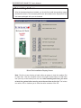
Installing Software ......................................................................................... 5-22
SuperDoctor III .............................................................................................. 5-23
Chapter 6 Advanced Chassis Setup
6-1
Static-Sensitive Devices .................................................................................. 6-1
Precautions ..................................................................................................... 6-1
Unpacking ....................................................................................................... 6-1
6-2
Control Panel .................................................................................................. 6-2
6-3
Installing the Baseboard into the Chassis ...................................................... 6-3
Tools Needed .................................................................................................. 6-3
6-4
System Fans ................................................................................................... 6-4
Replacing Fans ............................................................................................... 6-4
6-5
Drive Bay Installation/Removal ....................................................................... 6-6
Accessing the Drive Bays ............................................................................... 6-6
Hard Drive Midplane ....................................................................................... 6-6
SATA Drive Installation .................................................................................... 6-6
6-6
Power Supply .................................................................................................. 6-9
Power Supply Failure ...................................................................................... 6-9
Replacing the Power Supply ........................................................................... 6-9
Chapter 7 BIOS
7-1
Introduction...................................................................................................... 7-1
Starting BIOS Setup Utility .............................................................................. 7-1
How To Change the Configuration Data ......................................................... 7-1
Starting the Setup Utility ................................................................................. 7-2
7-2
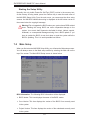
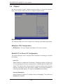
Main Setup ...................................................................................................... 7-2
7-3
Advanced Setup Configuration ....................................................................... 7-4
7-4
Chipset .......................................................................................................... 7-18
7-5
Server Management ...................................................................................... 7-25
7-6
iSCSI ............................................................................................................. 7-27
7-7
Boot Configuration ........................................................................................ 7-28
7-8
Security ......................................................................................................... 7-29
7-9
Save & Exit ................................................................................................... 7-30
Appendix A BIOS Error Beep Codes
Appendix B System Specifications
viii
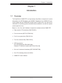
Chapter 1: Introduction
Chapter 1
Introduction
1-1
Overview
The SuperServer 5086B-TRF is a high-density SuperServer comprised of several
subsystems: the SC758 chassis, one X8OBN-F baseboard, four X8OBN-CPU processor boards and two X8OBN-BR1 bridge boards. Please refer to our web site for
information on operating systems that have been certified for use with the system
(www.supermicro.com).
Below is a list of the main hardware components included with the 5086B-TRF:
•
Eight passive CPU heatsinks (SNK-P0044P+)
•
Four air shrouds (MCP-310-75801-0N)
•
Four 9-cm system fans (FAN-0121L4)
•
Two 9-cm exhaust fans (FAN-0122L4)
•
SATA Accessories
One HDD backplane (BPN-SAS-I28A)
Sixteen 2.5" hard drive carriers (MCP-220-97301-0B)
•
One set of rackmount hardware (MCP-290-00057-0N)
•
One CD containing drivers and utilities
•
5086B-TRF User's Manual
1-1
SUPERSERVER 5086B-TRF User's Manual
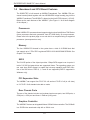
1-2
Baseboard and CPU Board Features
The 5086B-TRF is built around an X8OBN-F baseboard. Four X8OBN-CPU processor boards (linked together with two X8OBN-BR1 bridge boards) plug into the
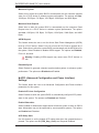
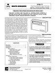
X8OBN-F baseboard. The X8OBN-F is based on the Intel® 7500 chipset (+ ICH10).
Below are the main features of the X8OBN-F. (See Figure 1-1 for a block diagram
of the chipset.)
Processors
Each X8OBN-CPU processor board supports single or dual Intel® Xeon 7500 Series
8-core processors and next generation Xeon E7 8800 family 10-core processors.
Please refer to the product page on our web site for a complete listing of supported
processors (www.supermicro.com).
Memory
The four X8OBN-CPU boards in the system have a total of 64 DIMM slots that
can support up to 2 TB of ECC registered DDR3-1333/1066/978/800 SDRAM. See
Chapter 5 for details.
SATA
The ICH10R portion of the chipset provides 3 Gbps SATA support over six ports. A
total of 16 SAS hot-swap drives are supported. Notes: The operating system you
use must have RAID support to enable the hot-swap capability and RAID function of the SAS drives. RAID 0, 1, 5 and 10 are supported (RAID 5 supported in
Windows only).
PCI Expansion Slots
The X8OBN-F can support four PCI-E 2.0 x16 and two PCI-E 2.0 x8 (in x16 slots)
or 10 PCI-E 2.0 x8 standard size add-on cards.
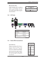
Rear Chassis Ports
The rear of the chassis includes one keyboard and mouse ports, two USB ports, a
COM port, a VGA port and three 1 Ethernet (LAN) ports.
Graphics Controller
The X8OBN-F features an integrated Matrox G200eW video controller. The G200eW
is a 2D/3D/video accelerator chip with a 128-bit core.
1-2
QPI 6.4GT/s
1-3
GLAN RJ45 CONN
GLAN RJ45 CONN
KAWELA
Slot7 PCI-e x8 (X8)
Slot8 PCI-e x16 (X16)
Slot9 PCI-e x8 (X8)
Slot0 PCI-e x16 (X16)
x4
MUX x8
x8
MUX x8
x8
IOH2
BOXBORO
QPI 6.4GT/s
QPI 6.4GT/s
DDR3 800/1066 * 1 DDR3 Ch.A MB0 SMI 6.4GT/s
SMI 6.4GT/s
DDR3 800/1066 * 1 DDR3 Ch.B
DDR3
Ch.C
SMI 6.4GT/s
DDR3 800/1066 * 1
MB1 SMI 6.4GT/s
CPU4 QPI 6.4GT/s CPU5
DDR3 800/1066 * 1 DDR3 Ch.D
DDR3 800/1066 * 1 DDR3 Ch.E MB2 SMI 6.4GT/s
SMI 6.4GT/s
DDR3 800/1066 * 1 DDR3 Ch.F
DDR3
Ch.G
DDR3 800/1066 * 1
SMI 6.4GT/s
MB3 SMI 6.4GT/s
DDR3 800/1066 * 1 DDR3 Ch.H
QPI 6.4GT/s
10/100 RJ45
QPI 6.4GT/s
KB/MS Connector
COM2 Header
COM1 Connector
VGA Connector
10/100 PHY
Slot1 PCI-e x16 (x8)
Slot2 PCI-e x16 (x8)
Slot3 PCI-e x8 (x8)
Slot4 PCI-e x16 (x16)
MUX
x8
x8
x8
TPM
Internal
Hheader
TPM
SLB9635
SIO
W83527HG
BMC
WPCM450
PEX8648
PCI-E
BRIDGE
LPC
PCI 32/33
CPU3
USB 2.0 x4
USB 2.0 x2
CPU1
HWM
W83795ADG
SM BUS
SPI
SATA
ICH10R USB 2.0 x2
ESI (x4)
ESI (x4)
IOH1
BOXBORO
USB 2.0 X2
x16
x8
x8
x8
Slot6 PCI-e x16 (x16)
Slot5 PCI-e x8 (x8)
MUX
DDR3 800/1066 * 1 DDR3 Ch.E MB2 SMI 6.4GT/s
DDR3 800/1066 * 1 DDR3 Ch.F
DDR3 800/1066 * 1 DDR3 Ch.G MB3 SMI 6.4GT/s
DDR3 800/1066 * 1 DDR3 Ch.H
DDR3 800/1066 * 1 DDR3 Ch.A MB0 SMI 6.4GT/s
DDR3 800/1066 * 1 DDR3 Ch.B
DDR3 800/1066 * 1 DDR3 Ch.C MB1 SMI 6.4GT/s CPU0
QPI 6.4GT/s
DDR3 800/1066 * 1 DDR3 Ch.D
QPI 6.4GT/s
DDR3 800/1066 * 1 DDR3 Ch.A MB0 SMI 6.4GT/s
DDR3 800/1066 * 1 DDR3 Ch.B
DDR3 800/1066 * 1 DDR3 Ch.C MB1 SMI 6.4GT/s
CPU2
DDR3 800/1066 * 1 DDR3 Ch.D
DDR3 800/1066 * 1 DDR3 Ch.E MB2 SMI 6.4GT/s
DDR3
Ch.F
DDR3 800/1066 * 1
DDR3 800/1066 * 1 DDR3 Ch.G MB3 SMI 6.4GT/s
DDR3 800/1066 * 1 DDR3 Ch.H
QPI 6.4GT/s
DDR3 Ch.A
MB0 DDR3 Ch.B DDR3 800/1066 * 1
DDR3 800/1066 * 1
DDR3 Ch.C DDR3 800/1066 * 1
MB1 DDR3 Ch.D
DDR3 800/1066 * 1
DDR3 Ch.E
MB2 DDR3 Ch.F DDR3 800/1066 * 1
DDR3 800/1066 * 1
DDR3 Ch.G DDR3 800/1066 * 1
MB3 DDR3 Ch.H
DDR3 800/1066 * 1
QPI 6.4GT/s
DDR3 Ch.A DDR3 800/1066 * 1
DDR3 Ch.B DDR3 800/1066 * 1
DDR3 Ch.C DDR3 800/1066 * 1
DDR3 Ch.D DDR3 800/1066 * 1
DDR3 Ch.E DDR3 800/1066 * 1
DDR3 Ch.F DDR3 800/1066 * 1
DDR3 Ch.G DDR3 800/1066 * 1
DDR3 Ch.H DDR3 800/1066 * 1
QPI 6.4GT/s
DDR3 800/1066 * 1 DDR3 Ch.A MB0 SMI 6.4GT/s
SMI 6.4GT/s MB0
DDR3 800/1066 * 1 DDR3 Ch.B
DDR3
Ch.C
DDR3 800/1066 * 1
SMI 6.4GT/s MB1
MB1 SMI 6.4GT/s
CPU6 QPI 6.4GT/s CPU7
DDR3 800/1066 * 1 DDR3 Ch.D
DDR3 800/1066 * 1 DDR3 Ch.E MB2 SMI 6.4GT/s
SMI 6.4GT/s MB2
DDR3 800/1066 * 1 DDR3 Ch.F
DDR3 800/1066 * 1 DDR3 Ch.G MB3 SMI 6.4GT/s
SMI 6.4GT/s MB3
DDR3 800/1066 * 1 DDR3 Ch.H
QPI 6.4GT/s
QPI 6.4GT/s
DDR3 800/1066 * 1
DDR3 800/1066 * 1
DDR3 800/1066 * 1
DDR3 800/1066 * 1
12 * FAN
SPI BIOS
6 * SATA Connectors
Stack 2 Ports
USB Connector
2 * USB 2 Ports
Internal Headers
2 * USB Type A
Internal Connectors
DDR3 800/1066 * 1
DDR3 800/1066 * 1
DDR3
Ch.G
DDR3 800/1066 * 1
SMI 6.4GT/s MB3
DDR3 Ch.H
DDR3 800/1066 * 1
SMI 6.4GT/s MB2 DDR3 Ch.E
DDR3 Ch.F
SMI 6.4GT/s MB0 DDR3 Ch.A
DDR3 Ch.B
SMI 6.4GT/s MB1 DDR3 Ch.C
DDR3 Ch.D
DDR3 Ch.A
SMI 6.4GT/s MB0 DDR3 Ch.B DDR3 800/1066 * 1
DDR3 800/1066 * 1
DDR3 Ch.C DDR3 800/1066 * 1
SMI 6.4GT/s MB1 DDR3 Ch.D
DDR3 800/1066 * 1
DDR3 Ch.E
SMI 6.4GT/s MB2 DDR3 Ch.F DDR3 800/1066 * 1
DDR3 800/1066 * 1
DDR3 Ch.G
SMI 6.4GT/s MB3 DDR3 Ch.H DDR3 800/1066 * 1
DDR3 800/1066 * 1
Chapter 1: Introduction
Figure 1-1. Intel 7500 + ICH10R Chipset:
System Block Diagram
Note: This is a general block diagram. Please see Chapter 5 for details.
SUPERSERVER 5086B-TRF User's Manual
1-3
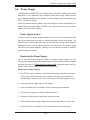
Server Chassis Features
System Power
The SC758 features four Gold Level 1400W power supply power modules (2+2
redundancy) to provide 2800W of uninterrupted power. This power redundancy
feature also allows you to replace a failed power module without shutting down
the system.
Hard Drives
The SC758 supports up to 16 2.5" hard drives. Six of these may be 3 Gbps SATA
drives as supported by the X8OBN-F baseboard. These drives are hot-swappable
units and are connected to a midplane that provides power and control. Note: The
operating system you use must have RAID support to enable the hotswap capability of the SATA drives.
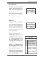
Front Control Panel
The control panel on the SuperServer 5086B-TRF provides system monitoring and
control. LEDs indicate system power, network (NIC) activity, system overheat, hard
drive activity and power supply failure. Reset and power buttons are also found on
the control panel.
Cooling System
The SC758 chassis has six 9-cm fans. The fans are hot-pluggable units that may
be replaced without removing power from the system. An air shroud is also included
to optimize air flow.
1-4
Chapter 1: Introduction
1-4
Contacting Supermicro
Headquarters
Address:
Super Micro Computer, Inc.
980 Rock Ave.
San Jose, CA 95131 U.S.A.
Tel:
+1 (408) 503-8000
Fax:
+1 (408) 503-8008
Email:
[email protected] (General Information)
[email protected] (Technical Support)
Web Site:
www.supermicro.com
Europe
Address:
Super Micro Computer B.V.
Het Sterrenbeeld 28, 5215 ML
's-Hertogenbosch, The Netherlands
Tel:
+31 (0) 73-6400390
Fax:
+31 (0) 73-6416525
Email:
[email protected] (General Information)
[email protected] (Technical Support)
[email protected] (Customer Support)
Asia-Pacific
Address:
Super Micro Computer, Inc.
4F, No. 232-1, Liancheng Rd.
Chung-Ho 235, Taipei County
Taiwan, R.O.C.
Tel:
+886-(2) 8226-3990
Fax:
+886-(2) 8226-3991
Web Site:
www.supermicro.com.tw
Technical Support:
Email:
[email protected]
Tel:
886-2-8226-5990
1-5
SUPERSERVER 5086B-TRF User's Manual
Notes
1-6
Chapter 2: Server Installation
Chapter 2
Server Installation
2-1
Overview
This chapter provides a quick setup checklist to get your SuperServer 5086B-TRF
up and running. Following these steps in the order given should enable you to have
the system operational within a minimum amount of time. This quick setup assumes
that your system has come to you with the processors and memory preinstalled. If
your system is not already fully integrated with a baseboard, processors, system
memory etc., please turn to the chapter or section noted in each step for details on
installing specific components.
The 5086B-TRF may be employed either as a tower or mounted in a rack as a 5U
rackmount chassis. If using it as a tower unit, please read the Server Precautions
in the next section and then skip ahead to Section 2-5.
2-2
Unpacking the System
You should inspect the box the system was shipped in and note if it was damaged
in any way. If the server itself shows damage you should file a damage claim with
the carrier who delivered it.
Decide on a suitable location for the SuperServer 5086B-TRF. It should be situated
in a clean, dust-free area that is well ventilated. Avoid areas where heat, electrical
noise and electromagnetic fields are generated. You will also need it placed near
a grounded power outlet. Be sure to read the Rack and Server Precautions in the
next section.
2-3
Preparing for Setup
The box the system was shipped in may include two sets of rail assemblies, two
rail mounting brackets and mounting screws needed for installing the system into
a rack (optional kit). Follow the steps in the order given to complete the installation
process in a minimum amount of time. Please read this section in its entirety before
you begin the installation procedure outlined in the sections that follow.
2-1
SUPERSERVER 5086B-TRF User's Manual
Choosing a Setup Location
•
Leave enough clearance in front of the rack to enable you to open the front door
completely (~25 inches) and approximately 30 inches of clearance in the back
of the rack to allow for sufficient airflow and ease in servicing.
•
This product is for installation only in a Restricted Access Location (dedicated
equipment rooms, service closets and the like).
•
This product is not suitable for use with visual display work place devices
acccording to §2 of the the German Ordinance for Work with Visual Display
Units.
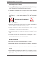
!
Warnings and Precautions!
!
Rack Precautions
•
Ensure that the leveling jacks on the bottom of the rack are fully extended to
the floor with the full weight of the rack resting on them.
•
In single rack installation, stabilizers should be attached to the rack. In multiple
rack installations, the racks should be coupled together.
•
Always make sure the rack is stable before extending a component from the
rack.
•
You should extend only one component at a time - extending two or more simultaneously may cause the rack to become unstable.
Server Precautions
•
Review the electrical and general safety precautions in Chapter 4.
•
Determine the placement of each component in the rack before you install the
rails.
•
Install the heaviest server components on the bottom of the rack first, and then
work up.
•
Use a regulating uninterruptible power supply (UPS) to protect the server from
power surges, voltage spikes and to keep your system operating in case of a
power failure.
2-2
Chapter 2: Server Installation
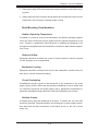
•
Allow the hot plug SATA drives and power supply modules to cool before touching them.
•
Always keep the rack's front door and all panels and components on the servers
closed when not servicing to maintain proper cooling.
Rack Mounting Considerations
Ambient Operating Temperature
If installed in a closed or multi-unit rack assembly, the ambient operating temperature of the rack environment may be greater than the ambient temperature of the
room. Therefore, consideration should be given to installing the equipment in an
environment compatible with the manufacturer’s maximum rated ambient temperature (Tmra).
Reduced Airflow
Equipment should be mounted into a rack so that the amount of airflow required
for safe operation is not compromised.
Mechanical Loading
Equipment should be mounted into a rack so that a hazardous condition does not
arise due to uneven mechanical loading.
Circuit Overloading
Consideration should be given to the connection of the equipment to the power
supply circuitry and the effect that any possible overloading of circuits might have
on overcurrent protection and power supply wiring. Appropriate consideration of
equipment nameplate ratings should be used when addressing this concern.
Reliable Ground
A reliable ground must be maintained at all times. To ensure this, the rack itself
should be grounded. Particular attention should be given to power supply connections other than the direct connections to the branch circuit (i.e. the use of power
strips, etc.).
2-3
SUPERSERVER 5086B-TRF User's Manual
2-4
Installing the System into a Rack
This section provides information on installing the system into a rack unit. Rack
installation requires the use of a rackmount kit. If the system has already been
mounted into a rack or if you are using it as a tower, you can skip ahead to Sections 2-5 and 2-6.
There are a variety of rack units on the market, which may mean the assembly
procedure will differ slightly. The following is a guideline for installing the server into
a rack with the rack rails provided in the rackmount kit. You should also refer to the
installation instructions that came with the rack unit you are using. Note: This rail
will fit a rack between 26.5" and 36.4" deep.
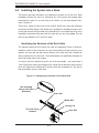
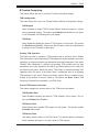
Identifying the Sections of the Rack Rails
The optional rackmount kit includes two rack rail assemblies. Each of these assemblies consist of three sections: an inner fixed chassis rail that secures to the
chassis, an outer rack rail that secures directly to the rack itself and a middle rail
which extends from the outer rail. These assemblies are specifically designed for
the left and right side of the chassis.
To remove the inner chassis rail, pull it out as far as possible - you should hear a
"click" sound as a locking tab emerges from inside the rail assembly and locks the
inner rail. Depress the locking tab to pull the inner rail completely out. Do this for
both assemblies (one for each side).
Figure 2-1. Identifying the Sections of the Rack Rails
Rail Assembly
(Shown with Rails
Retracted)
Outer Rail
Middle Rail
Locking Tab
This Side Faces
Outward
Inner Rail
2-4
Chapter 2: Server Installation
Locking Tabs
Each inner rail has a locking tab. This tab locks the chassis into place when installed
and pushed fully into the rack. These tabs also lock the chassis in place when fully
extended from the rack. This prevents the server from coming completely out of
the rack when when the chassis is pulled out for servicing.
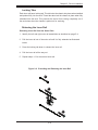
Releasing the Inner Rail
Releasing Inner Rail from the Outer Rails
1. Identify the left and right outer rail assemblies as described on page 5-4.
2. Pull the inner rail out of the outer rail until it is fully extended as illustrated
below.
3. Press the locking tab down to release the inner rail.
4. Pull the inner rail all the way out.
5. Repeat steps 1-3 for the second outer rail.
Figure 2-2. Extending and Releasing the Inner Rail
1
12
13
14
2-5
SUPERSERVER 5086B-TRF User's Manual
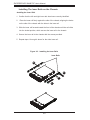
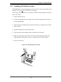
Installing The Inner Rails on the Chassis
Installing the Inner Rails
1. Confirm that the left and right inner rails have been correctly identified.
2.
Place the inner rail firmly against the side of the chassis, aligning the hooks
on the side of the chassis with the holes in the inner rail.
3. Slide the inner rail forward toward the front of the chassis until the rail clicks
into the locked position, which secures the inner rail to the chassis.
4. Secure the inner rail to the chassis with the screws provided.
5. Repeat steps 1 through 4 above for the other inner rail.
Figure 2-3. Installing the Inner Rails
Inner Rails
14
12
14
13
2-6
Chapter 2: Server Installation
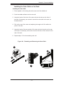
Installing the Outer Rails on the Rack
Installing the Outer Rails
1. Press upward on the locking tab at the rear end of the middle rail.
2. Push the middle rail back into the outer rail.
3. Hang the hooks of the front of the outer rail onto the slots on the front of
the rack. If necessary, use screws to secure the outer rails to the rack, as
illustrated above.
4. Pull out the rear of the outer rail, adjusting the length until it fits within the
posts of the rack.
5. Hang the hooks of the rear portion of the outer rail onto the slots on the rear
of the rack. If necessary, use screws to secure the rear of the outer rail to the
rear of the rack.
6. Repeat steps 1-5 for the remaining outer rail.
Figure 2-4. Extending and Releasing the Outer Rails
1
14
12
13
2-7
SUPERSERVER 5086B-TRF User's Manual
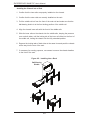
Installing the Chassis into a Rack
1. Confirm that the inner rails are properly installed on the chassis.
2. Confirm that the outer rails are correctly installed on the rack.
3. Pull the middle rail out from the front of the outer rail and make sure that the
ball-bearing shuttle is at the front locking position of the middle rail.
4. Align the chassis inner rails with the front of the middle rails.
5. Slide the inner rails on the chassis into the middle rails, keeping the pressure
even on both sides, until the locking tab of the inner rail clicks into the front of
the middle rail, locking the chassis into the fully extended position.
6. Depress the locking tabs of both sides at the same time and push the chassis
all the way into the rear of the rack.
7. If necessary for security purposes, use screws to secure the chassis handles
to the front of the rack.
Figure 2-5. Installing into a Rack
Ball-Bearing
Shuttle
2-8
Chapter 2: Server Installation
Optional Quick Installation Method
The following quick installation method may be used to install the chassis into a
rack.
1. Install the whole rail assembly onto the rack as described on page X-7.
2. Release the inner rail without retracting the middle rail.
3. Install the inner rails on the chassis as previously described on page X-6.
4. Install the chassis onto the middle rail as described in the previous section.
2-9
SUPERSERVER 5086B-TRF User's Manual
2-5
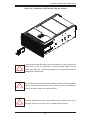
Checking the Configuration
After setting up the the system, you will need to open the unit to make sure the
various boards are properly installed and all the connections have been made.
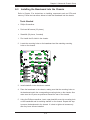
Accessing the Inside of the System
1. If rack mounted, first release the retention screws that secure the unit to the
rack.
2. Grasp the two handles on either side and pull the unit straight out until it
locks (you will hear a "click").
3. There are two screws that secure the cover to the chassis - remove these
first.
4. Locate the latch on the top (side if tower) of the chassis - depress where it
says "push" then lift the latch to release the cover.
5. Lift the cover from the chassis to gain full access to the inside of the server.
Checking the Components and Setup
1. You may have processors already installed into the CPU boards. Each processor should have its own heatsink attached. See Chapter 5 for instructions
on processor installation.
2. Your server may have come with system memory already installed. Make
sure all DIMMs are fully seated in their slots. For details on adding system
memory, refer to Chapter 5.
3. If desired, you can install add-on cards to the system. See Chapter 5 for
details on installing PCI add-on cards.
4. Make sure all power and data cables are properly connected and not blocking
the chassis airflow. See Chapter 5 for details on cable connections.
2-10
Chapter 2: Server Installation
2-6
Checking the Drive Bay Setup
Next, you should check to make sure the peripheral drives and the SATA drives and
backplane have been properly installed and all connections have been made.
Checking the Drives
1. All drives can be accessed from the front of the server. For servicing the peripheral drives, you will need to remove the top/left chassis cover. The SATA
disk drives can be installed and removed from the front of the chassis without
removing any chassis covers.
2. To install components into the 5.25" drive bays, you must first remove the
top/left chassis cover as described in the previous section. Refer to Chapter 6
for details.
3. Depending upon your system's configuration, your system may have one or
more drives already installed. If you need to install SATA drives, please refer
to Chapter 6.
Checking the Airflow
1. Airflow is provided by four hot-swap 9-cm chassis fans working in conjunction
with four air shrouds. Two 9-cm exhaust fans are also mounted at the rear of
the chassis. The system component layout was carefully designed to promote
sufficient airflow through the chassis.
2. Note that all power and data cables have been routed in such a way that they
do not block the airflow generated by the fans. Keep this in mind when you
reroute them after working on the system.
Supplying Power to the System
The last thing you must do is to provide input power to the system.
1. Plug the power cords from the power supplies unit into a high-quality power
strip that offers protection from electrical noise and power surges.
2. It is recommended that you use an uninterruptible power supply (UPS).
3. Depress the power on button on the front of the chassis.
2-11
SUPERSERVER 5086B-TRF User's Manual
Notes
2-12
Chapter 3: System Interface
Chapter 3
System Interface
3-1
Overview
There are several LEDs on two control panels as well as others on the drive carriers to keep you constantly informed of the overall status of the system as well as
the activity and health of specific components. The main power and reset buttons
are also located on the control panel. Two USB ports are also included for easy
front-side access.
3-2
Control Panel Buttons
Reset
The reset button reboots the system.
Power
This is the main power button, which is used to apply or turn off the main system
power. Turning off system power with this button removes the main power but keeps
standby power supplied to the system.
3-3
Control Panel LEDs
The control panel located on the front of the chassis has several LEDs. These
LEDs provide you with critical information related to different parts of the system.
This section explains what each LED indicates when illuminated and any corrective
action you may need to take
3-1
SUPERSERVER 5086B-TRF User's Manual
Power Fail
Indicates a power supply module has failed. The backup power supply module will
take the load and keep the system running but the failed module will need to be
replaced. Refer to Chapter 6 for details on replacing the power supply. This LED
should be off when the system is operating normally.
Overheat/Fan Fail:
When this LED flashes, it indicates a fan failure. When on continuously it indicates
an overheat condition, which may be caused by cables obstructing the airflow in
the system or the ambient room temperature being too warm. Check the routing of
the cables and make sure all fans are present and operating normally. You should
also check to make sure that the chassis covers are installed. Finally, verify that
the heatsinks are installed properly (see Chapter 5). This LED will remain flashing
or on as long as the indicated condition exists.
1
NIC1
Indicates network activity on the LAN1 port when flashing.
2
NIC2
Indicates network activity on the LAN2 port when flashing.
HDD
Indicates IDE channel activity, SATA drive and/or peripheral drive activity (if installed)
when flashing.
3-2
Chapter 3: System Interface
Power
Indicates power is being supplied to the system's power supply units. This LED
should normally be illuminated when the system is operating.
3-4
Drive Carrier LEDs
Each drive carrier has two LEDs:
•
Green: This LED will blink on and off to indicate read/write activity to the hard
drive.
•
Red: A steady red LED indicates a drive failure. If one of the drives fails, you
should be notified by your system management software. Please refer to Chapter
6 for instructions on replacing failed drives. If this LED flashes ~ once per second
(1 Hz) it indicates RAID rebuilding activity.
3-3
SUPERSERVER 5086B-TRF User's Manual
Notes
3-4
Chapter 4: System Safety
Chapter 4
System Safety
4-1
Electrical Safety Precautions
!
Basic electrical safety precautions should be followed to protect yourself from harm
and the SuperServer 5086B-TRF from damage:
•
Be aware of the locations of the power on/off switch on the chassis as well
as the room's emergency power-off switch, disconnection switch or electrical
outlet. If an electrical accident occurs, you can then quickly remove power from
the system.
•
Do not work alone when working with high voltage components.
•
Power should always be disconnected from the system when removing or installing main system components, such as the baseboard, memory modules and
floppy drive. When disconnecting power, you should first power down the system with the operating system. The unit has more than one power supply cord.
Disconnect both power supply cords before servicing to avoid electrical shock.
•
When working around exposed electrical circuits, another person who is familiar
with the power-off controls should be nearby to switch off the power if necessary.
•
Use only one hand when working with powered-on electrical equipment. This
is to avoid making a complete circuit, which will cause electrical shock. Use
extreme caution when using metal tools, which can easily damage any electrical
components or circuit boards they come into contact with.
•
Do not use mats designed to decrease static electrical discharge as protection
from electrical shock. Instead, use rubber mats that have been specifically
designed as electrical insulators.
•
The power supply power cords must include a grounding plug and must be
plugged into grounded electrical outlets.
4-1
SUPERSERVER 5086B-TRF User's Manual
•
This product may be connected to an IT power system. In all cases, make sure
that the unit is also reliably connected to Earth (ground).
•
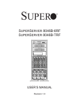
Baseboard Battery: CAUTION - There is a danger of explosion if the onboard
battery is installed upside down, which will reverse its polarites (see Figure 4-1).
This battery must be replaced only with the same or an equivalent type recommended by the manufacturer (CR2032). Dispose of used batteries according to
the manufacturer's instructions.
•
DVD-ROM Laser: CAUTION - this server may have come equipped with a
DVD-ROM drive. To prevent direct exposure to the laser beam and hazardous
radiation exposure, do not open the enclosure or use the unit in any unconventional way.
•
Mainboard replaceable soldered-in fuses: Self-resetting PTC (Positive Temperature Coefficient) fuses on the mainboard must be replaced by trained service
technicians only. The new fuse must be the same or equivalent as the one
replaced. Contact technical support for details and support.
4-2
General Safety Precautions
!
Follow these rules to ensure general safety:
•
Keep the area around the 5086B-TRF clean and free of clutter.
•
The 5086B-TRF weighs approximately 176 lbs (80 kg.) when fully loaded.
When lifting the system, two people at either end should lift slowly with their
feet spread out to distribute the weight. Always keep your back straight and lift
with your legs.
•
Place the chassis top cover and any system components that have been removed away from the system or on a table so that they won't accidentally be
stepped on.
•
While working on the system, do not wear loose clothing such as neckties and
unbuttoned shirt sleeves, which can come into contact with electrical circuits or
be pulled into a cooling fan.
4-2
Chapter 4: System Safety
•
Remove any jewelry or metal objects from your body, which are excellent metal
conductors that can create short circuits and harm you if they come into contact
with printed circuit boards or areas where power is present.
•
After accessing the inside of the system, close the system back up and secure
it to the rack unit with the retention screws after ensuring that all connections
have been made.
4-3
ESD Precautions
!
Electrostatic Discharge (ESD) is generated by two objects with different electrical
charges coming into contact with each other. An electrical discharge is created to
neutralize this difference, which can damage electronic components and printed
circuit boards. The following measures are generally sufficient to neutralize this
difference before contact is made to protect your equipment from ESD:
•
Use a grounded wrist strap designed to prevent static discharge.
•
Keep all components and printed circuit boards (PCBs) in their antistatic bags
until ready for use.
•
Touch a grounded metal object before removing the board from the antistatic
bag.
•
Do not let components or PCBs come into contact with your clothing, which may
retain a charge even if you are wearing a wrist strap.
•
Handle a board by its edges only; do not touch its components, peripheral chips,
memory modules or contacts.
•
When handling chips or modules, avoid touching their pins.
•
Put any PCI boards and peripherals back into their antistatic bags when not
in use.
•
For grounding purposes, make sure your computer chassis provides excellent
conductivity between the power supply, the case, the mounting fasteners and
the baseboard.
4-3
SUPERSERVER 5086B-TRF User's Manual
4-4
Operating Precautions
!
Care must be taken to assure that the chassis cover is in place when the 5086BTRF is operating to assure proper cooling. Out of warranty damage to the system
can occur if this practice is not strictly followed.
Figure 4-1. Installing the Onboard Battery
LITHIUM BATTERY
BATTERY HOLDER
!
Please handle used batteries carefully. Do not damage the battery in any way; a
damaged battery may release hazardous materials into the environment. Do not
discard a used battery in the garbage or a public landfill. Please comply with the
regulations set up by your local hazardous waste management agency to dispose
of your used battery properly.
4-4
Chapter 5: Advanced Setup
Chapter 5
Advanced Setup
This chapter provides detailed information on the X8OBN-F baseboard and the
boards that install into it. All jumpers and connections are described. A layout and
quick reference chart are also included in this chapter for your reference. Remember
to completely close the chassis when you have finished working with the board to
better cool and protect the system.
5-1
Handling the Baseboard
Electrostatic Discharge (ESD) can damage electronic components. To prevent damage to any printed circuit boards (PCBs), it is important to handle them very carefully
(see previous chapter). To prevent the baseboard from bending, keep one hand
under the center of the board to support it when handling. The following measures
are generally sufficient to protect your equipment from electric static discharge.
Precautions
•
Use a grounded wrist strap designed to prevent Electrostatic Discharge
(ESD).
•
Touch a grounded metal object before removing any board from its antistatic
bag.
•
Handle a board by its edges only; do not touch its components, peripheral chips,
memory modules or gold contacts.
•
When handling chips or modules, avoid touching their pins.
•
Put the baseboard, add-on cards and peripherals back into their antistatic bags
when not in use.
•
For grounding purposes, make sure your computer chassis provides excellent
conductivity between the power supply, the case, the mounting fasteners and
the baseboard.
5-1
SUPERSERVER 5086B-TRF User's Manual
5-2
Component Installation
The 5086B-TRF has a unique design that sets it apart from most server systems.
Processors are installed into four CPU boards, which are installed to a baseboard
and connect to each other with bridge boards. The following procedures should be
followed in order to access the system to add or change the system's processors
and memory. Follow these steps in reverse order when installing the boards back
into the system.
Begin by completely shutting down power to the system, including unplugging the
AC power cables. Then remove the chassis' top cover, which is secured to the
chassis with a single screw at the rear.
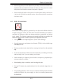
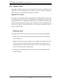
Removing a Bridge Module from the Chassis
1. Loosen the screws on the bridge board bracket.
2. Use even pressure to pull the bridge module out of the CPU modules.
Removing a CPU Module from the Chassis
1. Locate the red latches on the handles of the CPU module and place both
hands on the handles.
2. Using your thumbs, press both red latches outwards (towards the ends of the
board) to release the handles from their locked position.
3. Pull both handles of the CPU board upwards and gently lift the CPU module
out of the chassis. Do not grasp the middle of the CPU module to pull it out.
Note. All graphics and images are for illustration purposes only and may be slightly
different from the hardware in your system.
5-2
Chapter 5: Advanced Setup
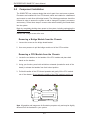
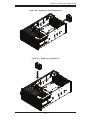
Removing an Air Shroud from a CPU Module
Each CPU board has its own air shroud, which must be removed before installing
processors or memory and re-attached before the CPU board is installed back into
the baseboard.
1. Each air shroud has four hooks at the corners that secure it to the CPU
board.
2. Locate and release the hooks from either edge of the CPU board.
CPU Board with Air Shroud
CPU Board with Air Shroud (side view)
5-3
CPU Board with Air Shroud (end view)
3. Lift the air shroud up and off of the CPU board.
SUPERSERVER 5086B-TRF User's Manual
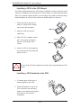
Installing a CPU to the CPU Board
The CPU board bracket that the CPU board is attached to does not present a flat
surface for installing CPUs and memory. For this reason, you should lay the board
either on a smaller support surface or on the edge of the table so that the board
bracket handles do not touch the surface the board bracket is resting on.
2
1. Press the socket clip down to
unlock it. Gently lift the socket
1
clip to open the load plate.
2. Align the CPU key with the
socket key.
3. Align CPU Pin 1 against socket
pin 1. Once they are aligned,
lower the CPU down to the
socket.
CPU Key
4. Once the CPU is fully seated on
the socket, press the socket clip
down to lock it.
!
Do not rub the CPU pins against the socket, which may damage the CPU
socket.
Installing a CPU Heatsink to the CPU
1. If needed, apply a thin layer of
thermal grease to the CPU.
2. Place the heatsink on top of the
CPU so that the two mounting
holes on the heatsink are aligned
with those on the retention
mechanism.
5-4
Chapter 5: Advanced Setup
3. Insert the two push-pins on the
sides of the heatsink through
the mounting holes on the CPU
board, and turn the push-pins
clockwise to lock them evenly.
Installing Memory on the CPU Board
The CPU board bracket that the CPU board is attached to does not present a flat
surface for installing CPUs and memory. For this reason, you should lay the board
either on a smaller support surface or on the edge of the table so that the board
bracket handles do not touch the surface the board bracket.
1. Align the key on the DIMM with the
key on the DIMM socket.
2. Insert the DIMM straight down and
into the DIMM socket by pressing
both ends of the DIMM at the same
time.
1
2
3. Press the tabs on the ends of the
DIMM socket inwards to lock the
DIMM Into place.
Note: make sure the tabs on all DIMM
sockets are pushed inwards regardless
of whether memory has been installed
or not. Otherwise they might interfere
with installing the CPU board back into
the chassis.
3
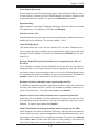
Memory Support
Each X8OBN-F CPU board supports up to 512 GB of registered ECC DDR3-1066
memory in 16 DIMM slots for a total of 2 TB of system memory.
Processor & Memory Module Population Configuration
For memory to work properly, refer to the tables below.
5-5
SUPERSERVER 5086B-TRF User's Manual
CPUs and their Corresponding DIMM Slots (on each CPU board)
CPU#
Corresponding DIMM Slots
CPU 1
P1-1A
P1-2A
P1-3A
P1-4A
P1-5A
P1-6A
P1-7A
P1-8A
CPU2
P2-1A
P2-2A
P2-3A
P2-4A
P2-5A
P2-6A
P2-7A
P2-8A
X8OBN-CPU
Rev.1.01
J47
J48
P2-DIMM6A
P1-DIMM4A
P2-DIMM5A
P1-DIMM3A
MB3
(for CPU2)
MB4
(for CPU2)
MB2
(for CPU1)
CPU2
MB1
(for CPU1)
P1-DIMM1A
P2-DIMM7A
P1-DIMM2A
P2-DIMM8A
P2-DIMM2A
P1-DIMM8A
P2-DIMM1A
P1-DIMM7A
MB1
(for CPU2)
MB2
(for CPU2)
CPU1
MB4
(for CPU1)
P2-DIMM3A
MB3
(for CPU1)
P1-DIMM5A
P1-DIMM6A
P2-DIMM4A
J35
J43
J44
J46
J45
J36
Processor and Memory Module Population (on each CPU board)
Number of
CPUs & DIMMs
2 CPUs &
8 DIMMs
2 CPUs &
10~16 DIMMs
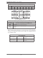
CPU and Memory Population Configuration Table
(For memory to work properly, please install DIMMs in pairs.)
CPU1 + CPU2
P1-1A/P1-3A/P1-5A/P1-7A, P2-1A/P2-3A/P2-5A/P2-7A
CPU1/CPU2
P1-1A/P1-3A/P1-5A/P1-7A, P2-1A/P2-3A/P2-5A/P2-7A + Any memory pairs in P1, P2
DIMM slots
Note: To optimize system performance, we recommend a 4 or 8 CPU configuration
as shown in the table below. Please note that a single CPU configuration has not
been validated by SMC.
CPU Configuration
4 CPU Configuration
2 CPUs per CPU Board
Two CPU boards required: installed
to CPU board slots 1 and 2 on the
base board.
8 CPU Configuration
2 CPUs per CPU Board
Four CPU boards required: installed to
all CPU board slots on the base board
(1 through 4).
5-6
Chapter 5: Advanced Setup
Installing a CPU Board to the Baseboard
After populating the CPU board with the desired components and reinstalling the
air shroud, you must install the CPU module to the baseboard.
1. Locate the CPU board slots on the X8OBN baseboard.
2. Using both hands, grab the two handles on the CPU module keeping the
CPU bracket facing toward the PCI-E slot area.
3. With the back plate (marked "Front") toward the left side of the chassis, align
the edge of the CPU board bracket with the guide rails, which are located on
the middle fan bracket and the rear of the chassis.
4. Insert the CPU module into the guide rails until the bottom of the CPU board
contacts the top of the CPU board slot. The gold fingers at the bottom of the
board should contact the slots at the same time that the handles touch the
frame.
5. Make sure the notch on each of the latches has entered the frame, then
press both handles inward to close them. Gently push the CPU board into the
slot until it is fully seated.
6. Press the red latches on the handles inward to lock the handles on the CPU
board bracket, which will secure the CPU module in place.
X8OBN-F Baseboard
Rev. 1.01
CPU Board Slot 4
CPU Board Slot 3
CPU Board Slot 2
CPU Board Slot 1
CPU Module Locked in Place
X8OBN Baseboard
!
If the CPU modules are not properly installed, the CPUs may sustain damage after powering on the system.
5-7
SUPERSERVER 5086B-TRF User's Manual
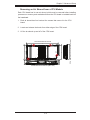
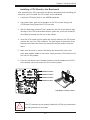
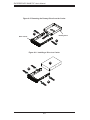
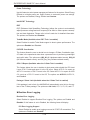
Installing a Bridge Module
Bridge boards are used to connect a pair of CPU boards installed in Slots 1 & 2
and/or Slots 3 & 4. (No bridge board is needed between Slots 2 and 3.)
To install the bridge module between the CPU boards, follow the steps below:
1. Place the bridge module on top of the two CPU boards, making sure that the
slot on the bridge board aligns with the gold fingers of the CPU boards. The
bridge board bracket is marked "Front" to indicate the correct orientation.
2. Press evenly on all sides of the module to fully seat the bridge board. Double
check to make sure that the bridge module is aligned horizontally after installation.
3. After installing both bridge modules, check that they are properly installed by
visually sighting along their length to make sure both are completely flat and
positioned below the rear chassis lip.
4. Secure the bridge module by tightening all four screws.
Figure 5-1. Installing a Bridge Module
Two Bridge Boards
Four CPU Boards
5-8
Chapter 5: Advanced Setup
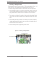
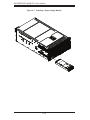
5-3
Installing PCI Add-On Cards
The 5086B-TRF can accommodate up to four PCI-E 2.0 x16 and two PCI-E 2.0 x8
cards (in x16 slots) or up to 10 PCI-E 2.0 x8 cards.
The AC plug cage may have to be pulled out when inserting add-on cards into
some of the slots:
1. Power down the server.
2. Loosen the thumbscrew on the side of the AC socket cage (and the screw on
the top if applicable).
3. Push the cage outwards from the chassis until there is enough room to install
add-on cards.
4. Install the add cards into the desired slots.
5. Push down with your thumbs evenly on both sides of the card.
6. Make any necessary connections, then return the AC plug cage back to its
original position and secure it with the screws that were removed earlier.
7. Power up the server.
Figure 5-2. Installing Add-on Cards
5-9
SUPERSERVER 5086B-TRF User's Manual
5-4
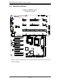
Baseboard Details
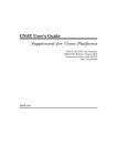
Figure 5-3. X8OBN-F Layout
(not drawn to scale)
JWD1
JOH1
JF1
X8OBN-F Baseboard
KB/Mouse
Fan6
Rev. 1.01
USB 0/1
IPMI LAN
COM1
CPU Board Slot 4
Fan5
Fan12
Fan 11
VGA
CPU Board Slot 3
JP18
Fan4
LAN1
CPU Board Slot 2
Fan 10
Fan 9
UID
JP19
JP17
JPT1
JUID_OW1
Fan3
JPL1
CPU Board Slot 1
JP16
JPWR3
Fan8
JPWR4
LED12
LED13
LED14
LED15
LED16
LED17
LED18
LED19
LAN CTRL
Slot 10: PCI-E 2.0 x16
Fan7
Slot 9: PCI-E 2.0 x8
PWR 1
I/O Hub 2
Slot 8: PCI-E 2.0 x16
I/O Hub 1
LED4
BMC CTRL
Slot 7: PCI-E 2.0 x8
JPG1
Slot 6: PCI-E 2.0 x16
Fan2
JP22
Slot 5: PCI-E 2.0 x8
JPWR1
Slot 4: PCI-E 2.0 x16
JPB1
PLX
PCI Bridge
Battery
JPWR2
BT1
JPRST1
JBT1
JD1
Slot 1: PCI-E 2.0 x8 in x16
JIPMB1
USB10 USB8
Buzzer
JWF1
JTPM1
I-SATA5 I-SATA3 I-SATA1
I-SATA4
I-SATA2 I-SATA0 COM2
T-SGPIO2
T-SGPIO2
Slot 2: PCI-E 2.0 x8 in x16
Fan1
ICH10R
JPME2
JPME1
PWR 2
Slot 3: PCI-E 2.0 x8
USB4/5
USB2/3
LED6
LAN2
JP21
JL1
Note: Jumpers not indicated are for test purposes only and should not have their
settings changed.
5-10
Chapter 5: Advanced Setup
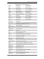
X8OBN-F Baseboard Quick Reference
Jumper
Description
Default Setting
JBT1
Clear CMOS
See Section 5-6
JPB1
BMC Enabled
Pins 1-2 (Enabled)
JPG1
VGA Enabled
Pins 1-2 (Enabled)
JPME1
ME Mode Recovery
Open (Normal)
JPME2
ME Mode Select
Open (Normal)
JPL1
GLAN1/GLAN2 Enable
Pins 1-2 (Enabled)
JPRST1
BMC Reset
Open (Normal)
JPT1
TPM Enabled
Pins 1-2 (Enabled)
JUID_OW1
UID Overwrite
Open (Normal)
JWD1
Watch Dog
Pins 1-2 (Reset)
Connector
Description
Fan1~6, 9~12
4-pin System Fan Headers (Fan1/Fan2, Fan9~Fan12) and
CPU Board Fan Headers (Fan3~Fan6)
Buzzer
Onboard Speaker
CPU Board Slots
1~4
CPU Board Slots 1~4 (for CPU boards)
COM1/COM2
Serial Port/Header
I-SATA 0~5
SATA Ports
JD1
Speaker/Power LED Indicator
JF1
Control Panel Header
JIPMB1
External BMC I2C Header (for IPMI Card)
JL1
Chassis Intrusion Header
JOH1
Overheat/Fan Fail LED
JP16~JP19
HDD Power Connectors
JP21/JP22
Main Power Supply Connectors (JP22: PWR1, JP21: PWR2)
JPWR1~JPWR4
8-Pin GPU Power Connectors
JTPM1
TPM (Trusted Platform Module) Port 80 Header
JWF1
SATA DOM (Device On Module) Power Connector
KB/MOUSE
Keyboard/Mouse Ports
LAN1/LAN2
G-bit Ethernet Ports 1/2
(IPMI) LAN
IPMI Dedicated LAN
T-SGPIO 1/2
Serial Link General Purpose I/O Headers
USB 0/1
Back Panel USB 0/1 Ports
USB 2/3, 4/5, 8, 10
Front Panel Accessible USB Headers
UID Switch
UID (Unit Identifier) Switch
5-11
SUPERSERVER 5086B-TRF User's Manual
5-5
Connector Definitions
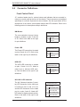
Front Control Panel
JF1 contains header pins for various buttons and indicators that are normally located on a control panel at the front of the chassis. These connectors are designed
specifically for use with Supermicro's server chassis. See the figure below for the
descriptions of the various control panel buttons and LED indicators. Refer to the
following section for descriptions and pin definitions.
NMI Button
NMI Button
Pin Definitions (JF1)
The non-maskable interrupt button
header is located on pins 19 and 20
of JF1. Refer to the table on the right
for pin definitions.
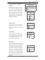
Power LED
Pin#
Definition
19
Control
20
Ground
Power LED
Pin Definitions (JF1)
The Power LED connection is located
on pins 15 and 16 of JF1. Refer to the
table on the right for pin definitions.
Pin#
Definition
15
3.3V
16
PWR LED
HDD LED
HDD LED
Pin Definitions (JF1)
The HDD LED connection is located
on pins 13 and 14 of JF1. Attach a
cable here to indicate HDD activity. See the table on the right for pin
definitions.
Pin#
Definition
13
3.3V Standby
14
HD Active
NIC1/NIC2 LED Indicators
The NIC (Network Interface Controller) LED connection for the LAN1 port
is located on pins 11 and 12 of JF1
and the LED connection for the LAN2
port is on pins 9 and 10. Attach NIC
LED cables to display network activity.
Refer to the table on the right for pin
definitions.
5-12
NIC1/2 LED
Pin Definitions (JF1)
Pin#
Definition
9
NIC 2 Activity LED
10
NIC 2 Link LED
11
NIC 1 Activity LED
12
NIC 1 Link LED
Chapter 5: Advanced Setup
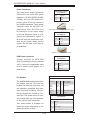
Overheat (OH)/Fan Fail/PWR Fail/
OH/Fan Fail/PWR Fail/UID LED
Pin Definitions (JF1)
UID LED
Connect an LED cable to the OH/
Fan Fail/FP UID connection on pins
7 and 8 of JF1 to provide advanced
warnings of a chassis overheat or fan
failure. This also works as the front
panel UID LED indicator. The red LED
Pin#
Definition
7
Red+ (Blue LED Cathode)
8
Blue+ (OH/Fan Fail/PWR Fail/
UID LED)
OH/Fan Fail Indicator
Status
takes precedence over the blue LED
State
by default. Refer to the table on the
right for pin definitions.
Off
Normal
On
Overheat
Flashing
Fan Fail
Power Fail LED
The Power Fail LED connection is
located on pins 5 and 6 of JF1. Refer to the table on the right for pin
definitions.
Definition
PWR Fail LED
Pin Definitions (JF1)
Pin#
Definition
5
3.3V
6
PWR Supply Fail
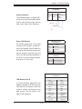
Reset Button
The Reset Button connection is located on pins 3 and 4 of JF1. Attach
it to a hardware reset switch on the
computer chassis. Refer to the table
on the right for pin definitions.
Reset Button
Pin Definitions (JF1)
Pin#
Definition
3
Reset
4
Ground
Power Button
The Power Button connection is located on pins 1 and 2 of JF1. Momentarily
contacting both pins will power on/off
the system. This button can also be
configured to function as a suspend
button with a setting in BIOS (see
Chapter 5). To turn off the power when
the system is set to suspend mode,
press the button for at least 4 seconds.
Refer to the table on the right for pin
definitions.
5-13
Power Button
Pin Definitions (JF1)
Pin#
Definition
1
Signal
2
Ground
SUPERSERVER 5086B-TRF User's Manual
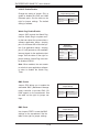
Power Connectors
GPU Power Connector
Pin Definitions
Two main power supply connectors
(JP21/JP22), four 8-pin GPU power
Pins
Definition
connectors (JPWR1/JPWR2/JPWR3/
1~3
+12V
JPWR4), and four HDD power con-
4~8
GND
nectors (JP16~JP19) are located on
the X8OBN baseboard. These power
connectors meet the SSI EPS 12V
specification. JP21 and JP22 must
(GPU PWR cables required for graphics cards)
be connected to your power supply
to provide adequate power to your
HDD Power Connector
Pin Definitions
system and components. Failure to
do so will void the manufacturer warranty on your power supply and the
system. See the table on the right for
pin definitions.
Pins
Definition
1~4
GND
5/6
+12V
7/8
+5V
(HDD PWR cable required for HDDs)
DOM Power Connector
DOM PWR
Pin Definitions
A power connector for SATA DOM
(Disk On Module) devices is located at
JWF1. Connect the appropriate cable
here to provide power support for a
DOM device.
Pin#
Definition
1
+5V
2
Ground
3
Ground
Fan Headers
Fan Headers
Fan Type
The X8OBN baseboard has six system
fan headers and four CPU card fan
headers. All these are 4-pin fans and
are backward compatible with traditional 3-pin fans. In addition, two 3-pin
IOH fan headers are located at Fan1
and Fan2. Fan speed control is available for 4-pin fans only.* See the tables
on the right for more information.
*Fan speed control is available via
Hardware Health Monitoring in the
Advanced Section of BIOS.
5-14
# of Pins Q'ty
Fan No.
IOH Fans
3-pin
Fan
2
Fan7 (IOH1)/
Fan8 (IOH2)
CPU_
Board
Fans
4-pin
Fan
4
Fans 3~6
System
Fans
4-pin
Fan
6
Fan1/Fan2, Fans
9~12
Fan Header
Pin Definitions
Pin#
Definition
1
Ground
2
+12V
3
Tachometer
4
PWR Modulation (4-pin fans only)
Chapter 5: Advanced Setup
Onboard Speaker
Pin Definition
Pin#
Onboard Speaker
The onboard speaker, located at SP1,
can be used to provide audible indica-
Definitions
Pin 1
Pos. (+)
Beep In
Pin 2
Neg. (-)
Alarm
Speaker
tions for various beep codes. See the
table on the right for pin definitions.
Power LED/Speaker
PWR LED Connector
Pin Definitions
On the JD1 header, pins 1-3 are used
for power LED indication, and pins 4-7
are for the speaker. See the tables on
the right for pin definitions. Please note
that the speaker connector pins (4-7)
are for use with an external speaker. If
you wish to use the onboard speaker,
close pins 6-7 with a cap.
Pin Setting
Definition
Pin 1
Anode (+)
Pin2
Cathode (-)
Pin3
NA
Speaker Connector
Pin Settings
Pin Setting
Definition
Pins 4-7
External Speaker
Pins 6-7
Onboard Speaker
TPM/Port 80 Header
Pin Definitions
Pin #
TPM Header/Port 80
A Trusted Platform Module/Port 80
header is located at JTPM1 to provide
TPM and Port 80 support, which will
enhance system performance and
data security. See the table on the
right for pin definitions.
5-15
Definition
Pin #
Definition
1
LCLK
2
GND
3
LFRAME#
4
<(KEY)>
5
LRESET#
6
+5V (X)
7
LAD 3
8
LAD 2
9
+3.3V
10
LAD1
11
LAD0
12
GND
13
SMB_CLK4
14
SMB_DAT4
15
+3V_DUAL
16
SERIRQ
17
GND
18
CLKRUN# (X)
19
LPCPD#
20
LDRQ# (X)
SUPERSERVER 5086B-TRF User's Manual
T-SGPIO 1/2 Headers
Two SGPIO (Serial-Link General
Purpose Input/Output) headers are lo-
T-SGPIO
Pin Definitions
Pin#
Definition
Pin
Definition
1
NC
2
NC
ers support Serial_Link interface for
3
Ground
4
Data
onboard SATA connections. See the
table on the right for pin definitions.
5
Load
6
Ground
7
Clock
8
NC
cated on the baseboard. These head-
NC = no connection
Chassis Intrusion
A Chassis Intrusion header is located
at JL1 on the baseboard. Attach an
appropriate cable from the chassis to
inform you of a chassis intrusion condition when the chassis is opened.
Chassis Intrusion
Pin Definitions
Pin#
Definition
1
Intrusion Input
2
Ground
Overheat LED
Pin Definitions
Overheat LED/Fan Fail
The JOH1 header is used to connect
an LED indicator to provide warning
of chassis overheating or fan failure.
This LED will blink when a fan failure
occurs. Refer to the table on right for
pin definitions.
5-16
Pin#
Definition
1
5vDC
2
OH Active
OH/Fan Fail LED
Status
State
Message
Solid
Overheat
Blinking
Fan Fail
Chapter 5: Advanced Setup
5-6
Jumper Settings
Explanation of Jumpers
To modify the operation of the baseboard, jumpers can be used to choose
between optional settings. Jumpers
3
2
1
3
2
1
Connector
Pins
create shorts between two pins to
change the function of the connector.
Pin 1 is identified with a square sol-
Jumper
der pad on the printed circuit board.
See the baseboard layout pages for
jumper locations.
Setting
Note: On a two-pin jumper, "Closed"
means the jumper is on both pins and
"Open" means the jumper is either on
only one pin or completely removed.
CMOS Clear
JBT1 is used to clear CMOS (which will also clear any passwords). Instead of pins,
this jumper consists of contact pads to prevent accidentally clearing the contents
of CMOS.
To clear CMOS,
1. First power down the system and unplug the power cord(s).
2. With the power disconnected, short the CMOS pads with a metal object such
as a small screwdriver.
3. Remove the screwdriver (or shorting device).
4. Reconnect the power cord(s) and power on the system.
Note: Do not use the PW_ON connector to clear CMOS.
VGA Enable/Disable
JPG1 allows you to enable or disable
the VGA port. The default position is on
pins 1 and 2 to enable VGA. See the
table on the right for jumper settings.
5-17
VGA Enable/Disable
Jumper Settings
Jumper Setting
Definition
Pins 1-2
Enabled
Pins 2-3
Disabled
SUPERSERVER 5086B-TRF User's Manual
LAN1/2 Enable/Disable
LAN1/2 Enable/Disable
Jumper Settings (JPL1)
Change the setting of jumper JPL1 to
enable or disable the LAN1 and LAN2
Jumper Setting
Ethernets ports. See the table on the
Pins 1-2
Enabled
right for jumper settings. The default
Pins 2-3
Disabled
Definition
setting is enabled.
Watch Dog Enable/Disable
Jumper JWD controls the Watch Dog
function. Watch Dog is a system monitor that can reboot the system when a
software application hangs. Jumping
pins 1-2 will cause WD to reset the system if an application hangs. Jumping
pins 2-3 will generate a non-maskable
interrupt signal for the application that
hangs. See the table on the right for
jumper settings. Watch Dog must also
be enabled in BIOS.
Watch Dog
Jumper Settings
Jumper Setting
Definition
Pins 1-2
Reset
Pins 2-3
NMI
Open
Disabled
Note: When enabled, the user needs
to write their own application software
in order to disable the Watch Dog
Timer.
BMC Enable
Jumper JPB1 allows you to enable the
embedded BMC (Baseboard Management) controller to provide IPMI 2.O/
KVM support on the serverboard. See
the table on the right for jumper settings.
BMC Enable
Jumper Settings
Jumper Setting Definition
Pins 1-2
BMC Enable
Pins 2-3
Normal (Default)
BMC Reset
Use Jumper JPRST1 to reset the BMC
settings on the serverboard. See the
table on the right for jumper settings.
5-18
BMC Reset
Jumper Settings
Jumper Setting
Definition
Closed
BMC Reset
Closed
Normal (Default)
Chapter 5: Advanced Setup
TPM Support Enable
JPT1 allows the user to enable TPM
(Trusted Platform Modules) support,
which will enhance data integrity and
TPM Support Enable
Jumper Settings
system security. See the table on the
right for jumper settings. The default
setting is enabled.
Note: For more information on IPMI con-
Jumper Setting
Definition
1-2
Enabled
2-3
Disabled
figuration, please refer to the WPCM 450
IPMI BMC User's Guide posted on our
Website @ http://www.supermicro.com.
ME Recovery
Close jumper JPME1 to use ME Firmware Recovery mode, which will limit
system resources for essential functionality use only without putting restrictions
on power use. In single operation mode,
an online upgrade will be available via
Recovery mode. See the table on the
right for jumper settings.
ME Recovery Select
Jumper Settings
Jumper Setting
Definition
Open
Normal (Default)
Closed
Manufacture Mode
JUID_OW1 (UID_Overwriting)
When the jumper JUID_OW1 is set to
Off (default), the red LED (Overheat/Fan
Fail/PWR Fail/UID LED) located on pin
8 of JF1 will take precedence over the
blue UID_LED located on pin 7 of JF1.
In this case, when the red LED is on,
the blue LED will be turned off. When
the red LED is off, the blue UID_LED
can be on or off. In other words, the red
LED signal overwrites the blue UID_LED
signal if J_UID-OW is set to off. When the
jumper J_UID_OW is On, the red LED
(OH/Fan Fail/PWR Fail/UID LED) and
the blue_UID_LED work independently
of each other. The red LED will have no
effect on the blue LED. See the table on
the right for jumper settings.
5-19
UID_Overwriting
Jumper Settings
Jumper
Definition
Off
Red OH/Fan Fail/PWR Fail LED
(pin 8 of JF1) takes precedence
over (overwrites) the blue
UID_LED (pin 7 of JF1).
Red LED: On, Blue LED: Off,
Red LED: Off, Blue LED: On
or Off
On
Red LED (OH/Fan Fail/PWR
Fail LED) and the blue UID_
LED function independently. The
red LED does not overwrite the
blue LED. The red LED has no
effect on the blue_UID LED
Red LED: On, Blue LED: On,Off
Red LED: Off, Blue LED: On,
Off
SUPERSERVER 5086B-TRF User's Manual
Manufacturer Mode Select
Close this jumper (JPME2) to bypass
SPI flash security and force the system
ME Mode Select
Jumper Settings
to use the Manufacturer Mode, which will
Jumper Setting
allow you to flash the system firmware
Open
Normal (Default)
Closed
Manufacture Mode
from a host server to modify system
settings. See the table on the right for
Definition
jumper settings.
5-7
Onboard Indicators
LAN LEDs
The Ethernet ports (located on the I/O
backplane) have two LEDs. On each
port: the yellow LED flashes to indicate
activity while the other LED may be
green, amber or off to indicate the
speed of the connection. See the table
on the right for the functions associated with the connection speed LED.
LAN1/2 LED
(Connection Speed Indicator)
LED Color
Definition
Off
No Connection or 10 Mb/s
Green
100 Mb/s
Amber
1 Gb/s
IPMI Dedicated LAN LEDs
In addition to LAN1/LAN2, a dedicated
IPMI LAN is also located on the I/O
backplane. The amber LED on the
right indicates activity, while the green
LED on the left indicates the speed of
the connection. See the table at right
for more information.
IPMI LAN Link LED (Left) &
Activity LED (Right)
Color/State
Definition
Link (Left)
Green: Solid
100 Mbps
Activity (Right)
Amber: Blinking
Active
Rear UID LED
The rear UID LED is located at LED6
on the backplane. This LED is used in
conjunction with the rear UID switch to
provide easy identification of a system
that might be in need of service. Refer
to UID Switch on Page 3-15 for more
information.
5-20
UID LED
Status
Color/State OS
Status
Blue: On
Windows OS
Unit Identified
Blue:
Blinking
Linux OS
Unit Identified
Chapter 5: Advanced Setup
BMC Heartbeat LED
A BMC Heartbeat LED is located at
LED4 on the baseboard. When this
BMC Heartbeat LED
Status
LED is blinking, the BMC is functioning normally. See the table at right for
Color/State
Definition
Green: Blinking
BMC: Normal
more information.
5-8
I/O Ports
2
5
1
3
4
6
7
8
9
Rear I/O Ports
5-9
1. Keyboard
6. COM1 Port
2. PS/2 Mouse
7. VGA Port
3. USB0
8. LAN1 Port
4. USB1
9. LAN2 Port
5. Dedicated IPMI LAN
10. UID Button
Serial ATA Connections
Serial_ATA
Pin Definitions
Serial ATA Ports
There are six Serial ATA Ports (ISATA0 ~I-SATA5) located on the
X8OBN-F. These ports, supported
by the Intel ICH10R South Bridge,
provide serial-link signal connections, which are faster than Parallel
ATA. See the table on the right for
pin definitions.
5-21
Pin#
Definition
1
Ground
2
TX_P
3
TX_N
4
Ground
5
RX_N
6
RX_P
7
Ground
10
SUPERSERVER 5086B-TRF User's Manual
5-10 Installing Software
After the hardware has been installed, you should first install the operating system
and then the drivers. The necessary drivers are all included on the Supermicro CDs
that came packaged with your serverboard.
Driver/Tool Installation Display Screen
Note: Click the icons showing a hand writing on paper to view the readme files
for each item. Click the computer icons to the right of these items to install each
item (from top to the bottom) one at a time. After installing each item, you must
re-boot the system before moving on to the next item on the list. The bottom
icon with a CD on it allows you to view the entire contents of the CD.
5-22
Chapter 5: Advanced Setup
SuperDoctor III
The SuperDoctor III program is a web-based management tool that supports remote
management capability. It includes Remote and Local Management tools. The local
management is called SD III Client. The SuperDoctor III program included on the
CD-ROM that came with your serverboard allows you to monitor the environment
and operations of your system. SuperoDoctor III displays crucial system information
such as CPU temperature, system voltages and fan status. See the Figure below
for a display of the SuperoDoctor III interface.
Note: The default User Name and Password for SuperDoctor III is ADMIN / ADMIN.
Note: When SuperDoctor III is first installed, it adopts the temperature threshold
settings that have been set in BIOS. Any subsequent changes to these thresholds
must be made within Super Doctor, as the Super Doctor settings override the BIOS
settings. To set the BIOS temperature threshold settings again, you would first need
to uninstall SuperDoctor III.
SuperDoctor III Interface Display Screen (Health Information)
5-23
SUPERSERVER 5086B-TRF User's Manual
SuperDoctor III Interface Display Screen (Remote Control)
Note: SuperDoctor III Software Revision 1.0 can be downloaded from our Web
Site at: ftp://ftp.supermicro.com/utility/Supero_Doctor_III/. You can also download
the SDIII User's Guide at: <http://www.supermicro.com/PRODUCT/Manuals/SDIII/
UserGuide.pdf>. For Linux, we will recommend using Supero Doctor II.
5-24
Chapter 6: Advanced Chassis Setup
Chapter 6
Advanced Chassis Setup
This chapter covers the steps required to install components and perform maintenance on the SC758 chassis. For component installation, follow the steps in the
order given to eliminate the most common problems encountered. If some steps
are unnecessary, skip ahead to the step that follows.
Tools Required: The only tool you will need to install components and perform
maintenance is a Philips screwdriver.
6-1
Static-Sensitive Devices
Electrostatic Discharge (ESD) can damage electronic components. To prevent
damage to any printed circuit boards (PCBs), it is important to handle them very
carefully. The following measures are generally sufficient to protect your equipment
from ESD damage.
Precautions
•
Use a grounded wrist strap designed to prevent static discharge.
•
Touch a grounded metal object before removing any board from its antistatic
bag.
•
Handle a board by its edges only; do not touch its components, peripheral chips,
memory modules or gold contacts.
•
When handling chips or modules, avoid touching their pins.
•
Put the serverboard, add-on cards and peripherals back into their antistatic
bags when not in use.
•
For grounding purposes, make sure your computer chassis provides excellent
conductivity between the power supply, the case, the mounting fasteners and
the serverboard.
Unpacking
The serverboard is shipped in antistatic packaging to avoid static damage. When
unpacking the board, make sure the person handling it is static protected.
6-1
SUPERSERVER 5086B-TRF User's Manual
Figure 6-1. Front and Rear Chassis Views
1
2
4
3
Front Chassis Features
1. Hot-swap Drive Bays
3. Power Supply Modules
2. Control Panel
4. Peripheral Drive Bays
3
1
4
2
Rear Chassis Features
6-2
1. 9-cm Exhaust Fans
3. AC Power Sockets
2. I/O Ports (see Chapter 5)
4. Expansion Card Slots
Control Panel
The control panel is connected to the serverboard through the midplane. The control
panel LEDs inform you of system status. See "Chapter 3: System Interface" for
details on the LEDs and the control panel buttons.
6-2
Chapter 6: Advanced Chassis Setup
6-3
Installing the Baseboard into the Chassis
Refer to Chapter 5 for instructions on installing components such as CPUs and
memory. Follow the instructions below to install the baseboard into the chassis.
Tools Needed
•
Phillips Screwdriver
•
Pan head #6 screws (23 pieces)
•
Standoffs (20 pieces, if needed)
1. First install the IO shield in the chassis.
2. Locate the mounting holes on the baseboard and the matching mounting
holes on the chassis.
JWD1
JOH1
KB/Mouse
X8OBN-F Baseboard
JF1
Fan6
IPMI LAN
USB 0/1
COM1
FP CRTL
Rev. 1.01
CPU Board Slot 4
Fan12
Fan5
J30
J29
Fan 11
VGA
CPU Board Slot 3
JP18
Fan 10
Fan 9
JP19
JP17
JPT1
JUID_OW1
Fan3
CPU Board Slot 1
LED12
LED13
LED14
LED15
LED16
LED17
LED18
LED19
LAN CTRL
JP16
JPWR4
Fan8
JPWR3
J32 J25
CPU Board Slot 2
UID
JPL1
LED6
LAN2
LAN1
Fan4
Slot10 PCI-E 2.0 x16
JP3
Fan7
Slot9 PCI-E 2.0 x8
I/O Hub 2
PWR 1
Slot8 PCI-E 2.0 x16
I/O Hub 1
LED4
Slot7 PCI-E 2.0 x8
JPG1
J26
Slot6 PCI-E 2.0 x16
PLX
PCI Bridge
Battery
JPWR2
JD1
ICH10R
USB4/5
USB2/3
Slot1 PCI-E 2.0 x8 in x16
JIPMB1
USB10 USB8
JWF1
JTPM1
I-SATA4
Buzzer
I-SATA5 I-SATA3 I-SATA1
I-SATA2 I-SATA0
COM2
Fan1
JPME1
Slot2 PCI-E 2.0 x8 in x16
PWR 2
BT1
JBT1
Slot3 PCI-E 2.0 x8
JPME2
JPRST1
JPB1
Slot4 PCI-E 2.0 x16
JP22
JPWR1 Fan2
Slot5 PCI-E 2.0 x8
T-SGPIO2
BMC CTRL
JL1 JP21
T-SGPIO1
3. Install standoffs in the chassis as needed.
4. Place the baseboard in the chassis, making sure that the mounting holes on
the baseboard match the corresponding mounting holes on the chassis. Also
make sure the IO ports are positioned toward the rear of the chassis.
5. Using the Phillips screwdriver, insert a pan head #6 screw into mounting hole
on the baseboard and its matching standoff on the chassis. Repeat this step
to secure the baseboard to the chassis. It is best to tighten all screws only
after they have all been installed.
6-3
SUPERSERVER 5086B-TRF User's Manual
6-4
System Fans
Four 9-cm cooling fans and two 9-cm exhaust fans provide the cooling for the
5086B-TRF. It is very important that the chassis top cover is properly installed for
the cooling air to circulate properly through the chassis.
System Fan Failure
Fan speed is controlled by system temperature via a BIOS setting. If a fan fails,
the remaining fan will ramp up to full speed and the overheat/fan fail LED on the
control panel will turn on. Replace the failed fan at your earliest convenience with
the same type and model (the system can continue to run with a failed fan). Remove the top chassis cover while the system is still running to determine which of
the four fans has failed.
Replacing Fans
The system power need not be shut down since the fans are all hot-pluggable.
1. Press the tab on the top of the fan housing of the failed fan and remove the
entire housing unit.
2. Replace the failed fan with an identical one (available from Supermicro). Position the new fan at its proper place in the chassis by fitting the fan with its
housing onto the fan mounts in the chassis. A "click" can be heard when the
fan (in its housing) as been fully inserted.
3. If the system is already powered on, the fan will activate immediately upon
being connected.
6-4
Chapter 6: Advanced Chassis Setup
Figure 6-2. Replacing a Rear Exhaust Fan
Figure 6-3. Replacing a System Fan
6-5
SUPERSERVER 5086B-TRF User's Manual
6-5
Drive Bay Installation/Removal
Accessing the Drive Bays
SATA Drives: You do not need to access the inside of the chassis or remove power
to replace or swap SATA drives. Proceed to the next step for instructions. You must
use 2.5" hard drives.
Hard Drive Midplane
The hard drives plug into a midplane that provides power, drive ID and bus termination. A RAID controller can be used with the midplane to provide data security.
The operating system you use must have RAID support to enable the hot-swap
capability of the hard drives. The midplane is already preconfigured, so no jumper
or switch configurations are required.
SATA Drive Installation
These drives are mounted in drive carriers to simplify their installation and removal
from the chassis. The carriers also help promote proper airflow for the drives. For
this reason, even empty carriers without hard drives installed must remain in the
chassis.
Removing an HDD Carrier from the Chassis (Figure 6-4)
1. Press the release button on the drive tray. This extends the drive tray handle.
2. Use the handle to pull the drive out of the chassis.
Installing a SATA Hard Drive (Figures 6-5 and 6-6)
1. Remove the screws securing the dummy drive to the drive carrier.
2. Remove the dummy drive. Place the carrier on a flat surface.
3. Slide the hard drive into the carrier with the printed circuit board side down.
4. Carefully align the mounting holes in both the drive tray and the hard drive.
5. Secure the hard drive to the tray using the screws provided.
6. Insert the drive carrier into the chassis. Make sure to close the carrier handle
to lock the carrier into place.
6-6
Chapter 6: Advanced Chassis Setup
Figure 6-4. Removing an HDD Carrier from the Chassis
A
A
!
Enterprise level hard disk drives are recommended for use in Supermicro
chassis and servers. For information on recommended HDDs, visit the
Supermicro Web site at http://www.supermicro.com/products/nfo/files/
storage/SAS-CompList.pdf
!
Use caution when working around the midplane. Do not touch the midplane
with any metal objects and make sure no cables touch the midplane or
obstruct the holes, which aid in proper airflow.
!
Important: Regardless of how many hard drives are installed, all drive carriers must remain in the drive bays to maintain proper airflow.
6-7
SUPERSERVER 5086B-TRF User's Manual
Figure 6-5. Removing the Dummy Drive from the Carrier
12
1
Dummy Drive
Drive Carrier
1
Figure 6-6. Installing a Drive to a Carrier
13
14
14
6-8
Chapter 6: Advanced Chassis Setup
6-6
Power Supply
The SuperServer 5086B-TRF has a 2800W (2+2) redundant 1400W power supply
subsystem of four separate power modules. Each power supply module has an
auto-switching capability, which enables it to automatically sense and operate at a
100V - 240V input voltage.
When fully inserted into the chassis, the power supplies connect automatically to a
power distribution board (PDB). The PDB in turn connects to the AC power sockets
located at the rear of the chassis.
Power Supply Failure
If either of the active power supply modules fail, one of the other modules will take
the full load and allow the system to continue operation without interruption. The
PWR Fail LED will illuminate and remain on until the failed unit has been replaced.
Replacement units can be ordered directly from Supermicro. The power supply
units have a hot-swap capability, meaning you can replace the failed unit without
powering down the system.
Replacing the Power Supply
You do not need to shut down the system to replace a power supply unit. The
backup power supply module will keep the system up and running while you replace
the failed hot-swap unit. Replace with the same model (see part number in the Appendix), which can be ordered directly from Supermicro.
Replacing the Power Supply
1. The SC758 chassis includes a redundant power supply subsystem consisting
of two active and two backup power modules. The system can continue to
operate without shuttng down if you remove only one power supply at a time.
2. Unplug the power supply that you will replace.
3. Push the release tab (on the back of the power supply) as illustrated.
4. Pull the power supply out using the handle provided.
5. Replace the failed power module with the same model.
6. Push the new power supply module into the power bay until you hear a click.
7. Plug the AC power cord back into the module and power up the server.
6-9
SUPERSERVER 5086B-TRF User's Manual
Figure 6-7. Installing a Power Supply Module
6-10
Chapter 7: BIOS
Chapter 7
BIOS
7-1
Introduction
This chapter describes the AMI BIOS Setup Utility for the X8OBN-F Baseboard.
The AMI ROM BIOS is stored in a Flash EEPROM and can be easily updated. This
chapter describes the basic navigation of the AMI BIOS Setup Utility screens.
Starting BIOS Setup Utility
To enter the AMI BIOS Setup Utility screens, press the <Delete> key while the
system is booting up.
Note: In most cases, the <Delete> key is used to invoke the AMI BIOS
setup screen. There are a few cases when other keys are used, such as
<F1>, <F2>, etc.
Each main BIOS menu option is described in this manual. The Main BIOS setup
menu screen has two main frames. The left frame displays all the options that can
be configured. Grayed-out options cannot be configured. Options in blue can be
configured by the user. The right frame displays the key legend. Above the key
legend is an area reserved for a text message. When an option is selected in the
left frame, it is highlighted in white. Often a text message will accompany it.
Note: the AMI BIOS has default text messages built in. Supermicro retains
the option to include, omit, or change any of these text messages.
The AMI BIOS Setup Utility uses a key-based navigation system called "hot keys".
Most of the AMI BIOS setup utility "hot keys" can be used at any time during the
setup navigation process. These keys include <F1>, <F10>, <Enter>, <ESC>, arrow keys, etc.
Note: Options printed in Bold are default settings.
How To Change the Configuration Data
The configuration data that determines the system parameters may be changed by
entering the AMI BIOS Setup Utility. This setup utility can be accessed by pressing
<Del> at the appropriate time during system boot.
Note: For AMI BIOS Recovery, please refer to the AMI BIOS Recovery
Instructions posted on our website at http://www.supermicro.com/support/
manuals/.
7-1
SUPERSERVER 5086B-TRF User's Manual
Starting the Setup Utility
Normally, the only visible Power-On Self-Test (POST) routine is the memory test.
As the memory is being tested, press the <Delete> key to enter the main menu of
the AMI BIOS Setup Utility. From the main menu, you can access the other setup
screens. An AMI BIOS identification string is displayed at the left bottom corner of
the screen below the copyright message.
Warning! Do not upgrade the BIOS unless your system has a BIOS-related
issue. Flashing the wrong BIOS can cause irreparable damage to the
system. In no event shall Supermicro be liable for direct, indirect, special,
incidental, or consequential damages arising from a BIOS update. If you
have to update the BIOS, do not shut down or reset the system while the
BIOS is updating. This is to avoid possible boot failure.
7-2
Main Setup
When you first enter the AMI BIOS Setup Utility, you will enter the Main setup screen.
You can always return to the Main setup screen by selecting the Main tab on the
top of the screen. The Main BIOS Setup screen is shown below.
BIOS Information: The following BIOS information will be displayed:
•
BIOS Vendor: This item displays the name of the BIOS vendor.
•
Core Version: This item displays the version of the BIOS Core currently used
in the system.
•
Project Version: This item displays the version of the mainboard currently used
in the system.
7-2
Chapter 7: BIOS
•
Build Date: This item displays the date when this BIOS was completed.
Memory Information: The following memory information will be displayed:
•
Total Memory: This item displays the size of memory available in the system.
System Language
The feature allows the user to select a language setting for the Setup utility. The
default setting is English.
System Time/System Date
These features allow the user to change the system time and date. Highlight System
Time or System Date using the arrow keys. Enter new values through the keyboard
and press <Enter>. Press the <Tab> key to move between fields. The date must be
entered in MM/DD/YY format. The time is entered in HH:MM:SS format.
Note: The time is in the 24-hour format. For example, 5:30 P.M. appears
as 17:30:00.
Access Level
The feature displays the privilege level that has been pre-set for the user for accessing the setup utility or the system.
7-3
SUPERSERVER 5086B-TRF User's Manual
7-3
Advanced Setup Configuration
Use the arrow keys to select the Advanced Setup menu and press <Enter> to access the submenu items.
Legacy OpROM Support
Use this feature to configure Option ROM settings which will allow the system to
boot up via a legacy network device.
Launch PXE OpROM
Select Enabled to boot up the system via a legacy network device. The options are
Enabled and Disabled.
Launch Storage OpROM
Select Enabled to boot up the system via a legacy mass storage device that has
the Option ROM capability built in. The options are Enabled and Disabled.
XPCI Subsystem Settings
PCI Bus Driver Version: This feature displays the version number of the PCI Bus
Driver used in this system.
PCI ROM Priority
This feature allows the user to specify which PCI Option ROM to use when multiple
Option ROMs are installed in the system. The options are Legacy ROM and EFI
(Extensible Firmware Interface)_Compatible ROM.
7-4
Chapter 7: BIOS
Above 4G Decoding
Select Enabled to allow a 64_bit_capable device to be decoded in the address
space above 4G if 64-bit_PCI_decoding is supported by the system. The options
are Enabled and Disabled.
PCI Common Settings
PCI Latency Timer
Select a value to be used by the PCI Latency Timer Register in bus clock calculation.
The options are 32 PCI Bus Clocks, 64 PCI Bus Clocks, 96 PCI Bus Clocks, 128
PCI Bus Clocks, 160 PCI Bus Clocks, 192 PCI Bus Clocks, 224 PCI Bus Clocks,
and 248 PCI Bus Clocks.
VGA Palette Snoop
If this feature is set to Enabled, a PCI card that does not have its own VGA color
palette built-in will detect a video_card palette to mimic it for color scheme support.
The options are Enabled and Disabled.
PERR# Generation
Select Enabled to allow a PCI device to generate a PERR number for a PCI Bus
Signal Error Event. The options are Enabled and Disabled.
SERR# Generation
Select Enabled to allow a PCI device to generate an SERR number for a PCI Bus
Signal Error Event. The options are Enabled and Disabled.
PCI Express Device Settings
Relaxed Ordering
Select Enabled to allow a PCI-E transaction to be completed prior to other transactions that were already enqueued. This violates PCI strict-ordering rules. The options
are Enabled and Disabled.
Extended Tag
Select Enabled to allow a PCI-E device to use the 8-bit Tag field as a requester.
The options are Enabled and Disabled.
No Snoop
Select Enabled to enable the "no_snoop bit" for a PCI-E device, which will reduce
front_side bus traffic for performance enhancement. The options are Enabled and
Disabled.
7-5
SUPERSERVER 5086B-TRF User's Manual
Maximum Payload
Select Auto to allow the system BIOS to automatically set the maximum payload
value for a PCI-E device to enhance system performance. The options are Auto,
128 Bytes, 256 Bytes, 512 Bytes, 1024 Bytes, 2048 Bytes, and 4096 Bytes.
Maximum Read Request
Select Auto to allow the system BIOS to automatically set the maximum Read
Request size for a PCI-E device to enhance system performance. The options
are Auto, 128 Bytes, 256 Bytes, 512 Bytes, 1024 Bytes, 2048 Bytes, and 4096
Bytes.
ASPM Support
This feature allows the user to set the Active State Power Management (ASPM)
level for a PCI-E device. Select Force L0 to force all PCI-E links to operate at L0
state. Select Auto to allow the system BIOS to automatically set the ASPM level for
the system. Select Disabled to disable ASPM support. The options are Disabled,
Force L0, and Auto.
Warning: Enabling ASPM support may cause some PCI-E devices to
fail!
Extended Synch
Select Enabled to generate extended synchronization patters to enhance system
performance. The options are Disabled and Enabled.
XACPI (Advanced Configuration and Power Interface)
Settings
This feature allows the user to set Advanced Configuration and Power Interface
parameters for this system.
Enable ACPI Auto Configuration
Select Enabled to allow the system BIOS to automatically configure ACPI parameters for the system. The options are Disabled and Enabled.
Enable Hibernation
Select Enabled for Hibernation support which will allow a system to enter an OS/S4
state. Hibernation may not be supported by some operation systems. The options
are Enabled and Disabled.
ACPI Sleep State
Use this feature to set the highest ACPI sleep state when the suspend button is
pressed. The options are S1 (CPU_Stop_Clock) and Suspend Disabled.
7-6
Chapter 7: BIOS
XTrusted Computing
This feature allows the user to configure Trusting Computing settings.
TPM Configuration
This future allows the user to set Trusted Platform Module Configuration settings.
TPM Support
Select Enabled to enable TPM (Trusted Platform Module) support for system
security and data integrity. The options are Disabled and Enabled. If this option
is set to Enabled, the following items will display.
TPM State
Select Enabled to display the status of TPM support for this system. The options
are Disabled and Enabled. Please note that a system reboot is needed before
a change on the TPM state to take effect.
Pending TPM Operation
This feature is used to schedule a TPM operation that is pending. Select "Enable
Take Ownership" to allow the pending TPM operation to take precedence over other
operations in the queue and be processed and executed immediately. If the option
"Disable Take Ownership" is selected, the pending TPM operation will not take
precedence over other operations and will be processed based on the order that
are placed in the queue. Select the option "TPM Clear" to delete all pending TPM
operations from the queue. If the option "None" is displayed, there is no pending
TPM operation in the queue. Please note that a system reboot is needed for any
change on the feature to become effective. The options are None, Enable Take
Ownership, Disable Take Ownership, and TPM Clear.
Current TPM Status Information
This feature displays the current status of the TPM items listed below.
TPM Enabled State
Select Enabled to display the status of "TPM Enabled" in this system. The options are Disabled and Enabled.
TPM Active State
Select Deactivate to disable TPM support for this system. The options are Deactivated and Activate.
TPM Active State
This feature lists the status of the TPM Owner. The default setting is UnOwned
which indicates that there is no owner listed for TPM support.
7-7
SUPERSERVER 5086B-TRF User's Manual
XWHEA Configuration
This feature allows the user to configure WHEA (Windows Hardware Error Architecture) support settings.
WHEA Support
Select Enabled to enable WHEA support which will provide a common infrastructure for the system to handle hardware errors on the Windows OS platforms in
order to reduce system crashes due to hardware errors and to enhance system
recovery and health monitoring. The default setting is Enabled.
XCPU Configuration
CPU Configuration
This feature allows the user to configure CPU support settings. It also displays the
status of the processor used in the system.
•
Processor Type: This item displays the CPU type for the mainboard.
•
Physical Processors: This item displays the number of physical processors
used in this system.
•
Logical Processors: This item displays the number of logical processors available for this system.
•
EMT 64: This item indicates if EMT 64 (Intel Extended Memory Technology for
64-bit) is supported by this system.
•
Processor Speed: This item displays the speed of the processor used in the
system.
•
Processor Stepping: This item indicates the revision level of the processor
used in the system.
•
Microcode Revision: This item indicates the revision number of the processor
core used in the system.
•
Processor Cores: This item indicates the number of processor cores available
in the system.
•
Intel HT Technology: This item indicates if Intel Hyper-Threading Technology is supported by the system. Intel TH Technology is used to enhance CPU
performance.
7-8
Chapter 7: BIOS
Clock Spread Spectrum
Select Enable to enable Clock Spectrum support, which will allow the BIOS to monitor and attempt to reduce the level of Electromagnetic Interference caused by the
components whenever needed. The options are Disabled and Enabled.
Hyper-threading
Select Enabled to use Hyper-Threading Technology, which will result in increased
CPU performance. The options are Disabled and Enabled.
Active Processor Core
Select Enabled to use a processor's second core and beyond. (Please refer to Intel's
website for more information.) The options are All, 1 and 2.
Limit CPUID Maximum
This feature allows the user to set the maximum CPU ID value. Enable this function to launch the legacy operating systems that cannot support processors with
extended CPUID functions. The options are Enabled and Disabled (for the Windows OS.)
Execute Disable Bit Capability (Available when supported by the OS and
the CPU)
Set to Enabled to support Execute Disable Bit which will allow the processor to
designate areas in the system memory where an application code can execute
and where it cannot, thus preventing a worm or a virus from flooding illegal codes
to overwhelm the processor or damage the system during an attack. The default is
Enabled. (Refer to Intel and Microsoft web Sites for more information.)
Hardware Prefetcher (Available when supported by the CPU)
If enabled, the hardware prefetcher will prefetch streams of data and instructions
from the main memory to the L2 cache in the forward or backward manner to improve CPU performance. The options are Disabled and Enabled.
Adjacent Cache Line Prefetch (Available when supported by the CPU)
If this item is set to Disabled, the CPU prefetches the cache line for 64 bytes. The
CPU prefetches both cache lines for 128 bytes as comprised if this item is set to
Enabled. The options are Disabled and Enabled.
Intel® Virtualization Technology (Available when supported by the CPU)
Select Enabled to use Intel Virtualization Technology which will allow one platform
to run multiple operating systems and applications in independent partitions, creating multiple "virtual" systems in one physical computer. The options are Enabled
and Disabled. Note: Please reboot the system for any change in this setting to
take effect. Please refer to Intel’s website for detailed information.
7-9
SUPERSERVER 5086B-TRF User's Manual
Power Technology
Use this feature to select power management features for the system. Select Energy
Efficient to minimize power use. Select Custom to customize power use settings.
The options are Disabled, Energy Efficient and Custom.
Intel® EIST Technology
EIST
EIST (Enhanced Intel SpeedStep Technology) allows the system to automatically
adjust processor voltage and core frequency in an effort to reduce power consumption and heat dissipation. Please refer to Intel’s web site for detailed information.
The options are Disabled and Enabled.
TurboBo Mode (Available when EIST Tech. is enabled)
Select Enabled to enable Turbo Mode support to boost system performance. The
options are Enabled and Disabled.
P-STATE Coordination
This feature allows the user to decide how to change a P-State Coordination type.
A P-state is the operational state when a processor/core is performing meaningful
and useful tasks. The options are HW_All (All Hardware-related events), SW_All
(All Software-related events), and SW_Any (Any Software-related events).
CPU C3 Report (Available when the C-State Tech is enabled)
This feature allows the user to decide at what power state should the CPU treat
it as a CPU C3 state and report it to the OS as so. Select ACPI C-2 to report an
ACPI C-2 event as a CPU C3 event to the OS. Select ACPI C-3 to report an ACPI
C-3 event as a CPU C3 event to the OS. The options are ACPI-C2, ACPI-C-3,
and Disabled.
Package C-State Limit (Available when the C-State Tech is enabled)
If this package is set to Auto, the AMI BIOS will automatically set a limit on the register of the C-State package. The options are No Limit, C0, C1, C3, C6, and C7.
XRuntime Error Logging
Runtime Error Logging
Select Enabled to support Runtime Error Logging. The options are Enabled and
Disabled. If this feature is set to Enabled, the following items will display:
PCI Error Logging Support
Select Enabled to enable error logging occurred in PCI/PCI-E connections. The
options are Enabled and Disabled.
7-10
Chapter 7: BIOS
Memory Correctable Error Threshold
This feature allows the user to enter the threshold value for memory correctable
errors. The default setting is 10.
XSATA Configuration
When this submenu is selected, the AMI BIOS automatically detects the presence
of the SATA devices and displays the following items:
•
SATA Port0/SATA Port1/SATA Port2/SATA Port3/SATA Port4/SATA Port5
SATA Mode
Use this feature to set the SATA mode for a SATA port selected by the user. Select
IDE mode to configure the SATA drive as an IDE drive. Select AHCI Mode to enable
the SATA drive to support AHCI Interface (Advanced Host Controller Interface).
Select RAID Mode to enable the SATA drive for RAID support. The options are IDE
Mode, AHCI Mode and RAID Mode.
When AHCI is selected, the item-AHCI CodeBase will display:
AHCI CodeBase (Available when RAID or AHCI is selected)
Select BIOS Native Module to use the BIOS Native Mode for the AHCI Interface.
Select Intel AHCI ROM to use the Intel AHCI ROM for the AHCI Interface. (Take
caution when using this function for this mode is for advanced programmers
only.)
When RAID is selected, the items: "AHCI CodeBase" (above), and "ICH RAID
Code Base" will appear.
ICH RAID Code Base (Available when the option-RAID is selected)
Select Intel to use Intel SATA RAID firmware for Intel SATA RAID configuration.
Select Adaptec to use Adaptec firmware for Adaptec SATA RAID configuration.
The options are Intel and Adaptec.
SATA Port0 Configuration/SATA Port1 Configuration/SATA Port2
Configuration/SATA Port3 Configuration//SATA Port4 Configuration//SATA
Port51 Configuration
These submenus allow the user to configure the following item for a SATA port
selected by the user.
eSATA Port Support
Select Enabled to enable a SATA port specified by the user for external SATA connection support. The options are Enable and Disabled.
7-11
SUPERSERVER 5086B-TRF User's Manual
XUSB Configuration
•
USB Devices: This feature displays the status of the USB devices detected in
the system.
Legacy USB Support
Select Enabled to support Legacy USB devices. If this item is set to Auto, the AMI
BIOS will automatically enable Legacy USB support if a legacy USB device is detected. The settings are Enabled, Disabled and Auto.
EHCI Hand-Off
Select Enabled to support the BIOS-Enhanced Host Controller Interface to provide a
workaround solution for an operating system that does not have EHCI Hand-Off support. When enabled, the EHCI Interface will be changed from the BIOS-controlled
to the OS-controlled. The options are Disabled and Enabled.
Device Reset Timeout
This setting allows you to decide how long the system should wait in an attempt
to detect the presence of a USB Mass Storage Device before it proceeds with the
next operation during POST. The options are 10 Seconds, 20 Seconds, 30 Seconds
and 40 Seconds.
Controller Timeout
This setting allows you to decide how long the system should wait for a USB controller or a Mass Storage device to complete its component-related activities, bulk
processing or data transferring before the system resume its normal operation during POST. The options are 1 Second, 5 Seconds, 10 Seconds, and 20 Seconds.
XHardware Health Event Monitoring
This feature allows the user to monitor system health and review the status of each
item as displayed.
CPU Overheat Alarm
This option allows the user to select the CPU Overheat Alarm setting that determines when the CPU OH alarm will be activated to provide warning of possible
CPU overheat.
The options are:
•
The Early Alarm: Select this setting to trigger the CPU overheat alarm as soon
as the CPU temperature reaches the CPU overheat threshold as predefined by
the CPU manufacturer.
7-12
Chapter 7: BIOS
•
The Default Alarm: Select this setting to trigger the CPU overheat alarm when
the CPU temperature reaches about 5oC above the threshold temperature as
predefined by the CPU manufacturer to give the CPU and system fans additional
time needed for CPU and system cooling.
Warning! To avoid possible system overheating, please be sure to provide
adequate airflow to your system.
Fan Speed Control Modes
This feature allows the user to decide how the system controls the speeds of the
onboard fans. The CPU temperature and the fan speed are correlated. When the
CPU on-die temperature increases, the fan speed will also increase for effective
system cooling. Select "Full Speed/FS" to allow the onboard fans to run at full
speed for maximum cooling. The FS setting is recommended for special system
configuration or debugging. Select "Performance/PF" for better system cooling. The
PF setting is recommended for high-power-consuming and high-density systems.
Select "Balanced/BL" for the onboard fans to run at a speed that will balance the
needs between system cooling and power saving. The BL setting is recommended
for regular systems with normal hardware configuration. Select "Energy Saving/ES"
for best power efficiency and maximum quietness. The Options are: Full Speed/FS,
Performance/PF, Balanced/BL, and Energy Saving/ES.
Fan Speed Readings
The following fan speeds are displayed: Fan1 Speed~Fan 12 Speeds
XBaseboard Voltage and Temperature
The he following temperature and voltage settings will be displayed (in degrees in
Celsius and Fahrenheit) as detected by the BIOS:
•
System Temperature, +1.8V Aux, +1.2V BMC, +1.0V NIC, +1,1V AUX, +1.0V
PEX, +5.0V, +1.1V, +1.8V, +12.0V, +1.5V, VBAT, +3.3V, and +3.3V VSB.
XCPU0 Voltage and Temperature~CPU7 Voltage and
Temperature
The following temperature and voltage settings of a CPU specified will be displayed
as detected by the BIOS:
•
System Temperature
Low – This level is considered as the ‘normal’ operating state. The CPU temperature is well below the CPU ‘Temperature Tolerance’ level. The onboard
7-13
SUPERSERVER 5086B-TRF User's Manual
fans and CPU run normally as configured in the BIOS. User intervention:
No action required.
Medium – The processor is running warmer. This is a ‘precautionary’ level
and generally means that there may be factors contributing to this condition,
but the CPU is still within its normal operating state and the CPU ‘Temperature Tolerance’ level. The onboard fans and CPU run normally as configured
in the BIOS. The fans may adjust to a faster speed depending on the Fan
Speed Control settings. User intervention: No action is required. However,
consider checking the CPU fans and the chassis ventilation for blockage.
High – The processor is running hot. This is a ‘caution’ level since the CPU’s
‘Temperature Tolerance’ has been reached or exceeded. The overheat alarm
may be triggered. The system may shut down if it continues for a long period
to prevent damage to the CPU.
•
CPU Vcore, CPU Vcache, CPU Millbrook 1.1V, CPU Branch0 VDD 1.5V, and
CCPU Branch1 VDD 1.5V
XSuper IO Configuration (for the W83527 HG chip)
•
Super IO Chip: This item displays the status of the onboard Super IO chip.
Watchdog Function
If enabled, the WatchDog Timer will cause the system to reboot when the system
is inactive for more than 5 minutes. The options are Enabled and Disabled.
XSuper IO Configuration (for the WPCM450 chip)
•
Super IO Chip: This item displays the status of the onboard Super IO chip.
XSerial Port 0 Configuration/Serial Port 1 Configuration
Serial Port
Select Enabled to enable a serial port specified by the user. The options are
Enabled and Disabled.
Device Settings
This feature indicated if reset is required or not for a serial port specified.
7-14
Chapter 7: BIOS
Change Settings
Use this feature to set the optimal Environment_Control_Interface (PECI) setting
for a serial port specified. The default setting is Auto, which will allow the AMI
BIOS to automatically select the best setting for the PECI platform.
Device Mode
Use this feature to select the desired mode for a serial port specified. The options
are Normal and High Speed.
XSerial Port Console Redirection
•
COM 1/COM2
These two submenus allow the user to configure the following Console Redirection
settings for a COM Port specified by the user.
Console Redirection
Select Enabled to use a COM Port selected by the user for Console Redirection.
The options are Enabled and Disabled.
XConsole Redirection Settings
This feature allows the user to specify how the host computer will exchange data
with the client computer, which is the remote computer used by the user.
Terminal Type
This feature allows the user to select the target terminal emulation type for
Console Redirection. Select VT100 to use the ASCII Character set. Select
VT100+ to add color and function key support. Select ANSI to use the Extended
ASCII Character Set. Select VT-UTF8 to use UTF8 encoding to map Unicode
characters into one or more bytes. The options are ANSI, VT100, VT100+, and
VT-UTF8.
Bits Per second
Use this feature to set the transmission speed for a serial port used in Console
Redirection. Make sure that the same speed is used in the host computer and the
client computer. A lower transmission speed may be required for long and busy
lines. The options are 9600, 19200, 57600 and 115200 (bits per second).
Data Bits
Use this feature to set the data transmission size for Console Redirection. The
options are 7 Bits and 8 Bits.
7-15
SUPERSERVER 5086B-TRF User's Manual
Parity
A parity bit can be sent along with regular data bits to detect data transmission
errors. Select Even if the parity bit is set to 0, and the number of 1's in data bits
is even. Select Odd if the parity bit is set to 0, and the number of 1's in data bits
is odd. Select None if you do not want to send a parity bit with your data bits
in transmission. Select Mark to add a mark as a parity bit to be sent along with
the data bits. Select Space to add a Space as a parity bit to be sent with your
data bits. The options are None, Even, Odd, Mark and Space.
Stop Bits
A stop bit indicates the end of a serial data packet. Select 1 Stop Bit for standard
serial data communication. Select 2 Stop Bits if slower devices are used. The
options are 1 and 2.
Flow Control
This feature allows the user to set the flow control for Console Redirection to
prevent data loss caused by buffer overflow. Send a "Stop" signal to stop sending data when the receiving buffer is full. Send a "Start" signal to start sending
data when the receiving buffer is empty. The options are None, Hardware RTS/
CTS, and Software Xon/Xoff.
Resolution 100x31
Use this feature to select the number of rows and columns used in Console
Redirection for legacy OS support. The options are 80x24 and 80x25.
Legacy OS Redirection
Select Enabled for extended-terminal resolution support. The options are Disabled, and Enabled.
•
Serial Port for Out-of-Band Management/Windows Emergency Management Services (EMS)
The submenu allows the user to configure the following Console Redirection
settings to support Out-of-Band Serial Port management.
Console Redirection
Select Enabled to use COM Port1 for Console Redirection. The options are
Enabled and Disabled.
Out-of_Band Management Port
This feature allows the user to select a serial port to be used by the Windows
Emergency Management Services (EMS) for remote system management during
an emergency. The options are COM 1 and COM 2.
7-16
Chapter 7: BIOS
Data Bits
This feature allows the user to select data bits for console redirection transmission. The options are 7 Bits and 8 Bits.
Parity
A parity bit can be sent with the data bits for data transmission errors. Select
Even if the parity bit is set to 0 and the number of 1's in data bits is even. Select
Odd if the parity bit is set to 0 and the number of 1's in data bits is odd. Select
None if you do not want to send a parity bit with your data bits in transmission.
Select Mark to add a mark as a parity bit to be sent with the data bits. Select
Space to add a Space as a parity bit to be sent with your data bits. The options
are None, Even, Odd, Mark and Space.
Stop Bits
A stop bit indicates the end of a serial data packet. Select 1 Stop Bit for standard
serial data communication. Select 2 Stop Bits if slower devices are used.
Terminal Type
This feature allows the user to select the target terminal emulation type for Console Redirection. Select VT100 to use ASCII Character set, Select VT100+ to
also include color, function key support. Select ANSI to use Extended ASCII Character Set. Select VT-UTF8 to use UTF8 encoding to map Unicode characters into
one or more bytes. The options are ANSI, VT100, VT100+, and VT-UTF8.
XNetwork Stack
Network Stack
Select Enabled enable PXE (Preboot Execution Environment) or UEFI (Unified
Extensible Firmware Interface) for network stack support. The options are Enabled
and Disabled.
7-17
SUPERSERVER 5086B-TRF User's Manual
7-4
Chipset
Use the arrow keys to select Chipset and press <Enter> to access the submenu
items. This submenu allows the user to configure chipset settings.
XNorth Bridge
This submenu allows the user to configure the following North Bridge parameters.
XBoxboro IOH Configuration
•
NB Revision: This item displays the Boxboro IOH revision number.
XIntel® VT for Direct I/O Configuration
This feature allows the user to configure Intel Virtualization Technology for Directed
I/O settings.
Intel VT-d
Select Enabled to enable Intel Virtualization Technology support for Direct I/O
VT-d by reporting the I/O device assignments to VMM through the DMAR ACPI
Tables. This feature offers fully-protected I/O resource-sharing across the Intel
platforms, providing the user with greater reliability, security and availability in
networking and data-sharing. The options are Enabled and Disabled.
Interrupt Remapping
Select Enabled to support VT-d Engine Interrupt Remapping. The options are
Enabled and Disabled.
7-18
Chapter 7: BIOS
Coherency Support
Select Enabled to enable Non-Isoch VT-d Engine Coherency support. The options are Enabled and Disabled.
ATS Support
Select Enabled to enable VT-d Engine Address Translation Services support.
The options are Enabled and Disabled.
Pass-through DMA
Select Enabled to enable Isoch/Non-Isoch VT-d Engine Pass-through DMA support. The options are Enabled and Disabled.
Intel® I/OAT
The Intel I/OAT (I/O Acceleration Technology) significantly reduces CPU overhead
by leveraging CPU architectural improvements, freeing resources for more other
tasks. The options are Disabled and Enabled.
DCA Support (Available when Intel I/OAT is enabled)
Select Enabled to use Intel's DCA (Direct Cache Access) Technology for data
transferring enhancement. The options are Enabled and Disabled.
PCIe Gen1 Device Support (Available when Intel I/OAT is enabled)
Select Enabled to support PCI-Express Gen. 1 devices. The options are Enabled
and Disabled.
IOH PCIe Port Bifurcation Support
This feature displays the following IOH PCIe Port Bifurcation Control settings,
which indicate how PCI-Express connections are split into different PCI-E signals
for various device support.
•
IOH1/IOU2
•
IOH1/IOU0
•
IOH1/IOU1
•
IOH2/IOU2
•
IOH2/IOU0
•
IOH2/IOU1
7-19
SUPERSERVER 5086B-TRF User's Manual
XIOH Thermal Sensors
This feature allows the user to configure integrated thermal sensor settings embedded in the 7500 chipset.
Thermal Sensors
Select Enabled to enable integrated thermal sensors embedded in the 7500
chipset. The options are Enabled and Disabled.
•
Low Threshold: This item displays the value of the low thermal threshold.
•
High Threshold: This item displays the value of the high thermal threshold.
•
Catastrophe Threshold: This item displays the value of the catastrophic threshold, beyond which the system enters into the catastrophic state.
XQPI Link
QuickPath Interconnect (QPI) is the connection between the processors and
the I/O hubs (IOH's). This submenu allows the user to configure the following
QPI settings.
•
Current QPI Link Speed: This item displays the current QPI Link speed.
•
Current QPI Link Frequency: This item displays the current QPI Link frequency.
CSI (Common System Interface) Link Speed
This feature allows the user to select the speed for CSI (Common System
Interface) Link, which is the former name for QPI Link. Select Fast for POR
(Power_On Reset)-related devices. The options are Slow and Fast.
QPI Link Frequency Select
This feature allows the user to set the QPI Link Frequency. Select Auto for the
AMI BIOS to automatically set the QPI Link Frequency for optimal system performance. The options are Auto, 4.8 GT/s, 5.866 GT/s, and 6.4 GT/s.
CRC Mode
Use this feature to enable the CRC (Cyclic Redundancy Check) mode in CSI and
select the method used by the CRC mode to detect any accidental changes to
raw computer data occurred in digital networks or storage devices. The options
are 8_bit CRC and 16_bit Rolling CRC.
7-20
Chapter 7: BIOS
CSI (Common System Interface) Scrambling
Select Enabled to support CSI data scrambling via 0:10h/11h:0:44h:22. The options are Enabled and Disabled.
Logical Interrupt Mode
Use this feature to select the Logical Interrupt mode for the programmable interrupt controller (PIC) embedded in a multiple-processor system. Select Flat mode
for the PIC to process interrupts in the linear, sequential format. Select Cluster
Mode for the PIC to process interrupts in the cascade format. The options are
Flat Mode and Cluster Mode.
Cluster Mode Check Sampling
Select Enabled for a system to check the APIC ID for non-zero. APIC ID is used
to identify a processor in multi-processor systems. The options are Enabled
and Disabled.
MMIOH Size per IOH
Use this feature to select the MMIOH Size to be allocated to every IOH in the
system. The options are 2G, 4G, 6G and 8G.
Intel reference Code
This item displays Intel IOH Reference code for the system.
Memory Information
The item displays the following memory information:
•
Total Memory: This item displays the total memory available in the system.
•
Current Memory Mode: This item displays the current memory mode used
in the system.
•
Current Memory Speed: This item displays the current memory speed of
the system.
•
Mirroring: This item indicates if memory mirroring is supported by the system
for data security enhancement.
•
Sparing: This item indicates if memory sparing is supported by the system
for memory performance enhancement.
Memory Configuration
This feature allows the user to configure the following memory settings:
7-21
SUPERSERVER 5086B-TRF User's Manual
Memory Init mode
Select Serial to set the memory initialization mode to Serial. Select Parallel to set
the memory initialization mode to Parallel. The options are Serial and Parallel.
Page Policy
This feature allows the user to select the memory page policy for virtual memory
support. Select Open for a memory control unit to issue a command to open a
memory page. Select Closed for the memory control unit to issue a command
to close a memory page. Select Adaptive to provide a flexible page policy to
better support each individual event. Select Multi-Cas Widget to simultaneously
provide memory support to multiple users in a multi-casting format. The options
are Closed, Open, Adaptive and Muliti-Cas Widget.
Mapping Policy
This feature allows the user to set the policy for memory mapping, which is a
file used by the virtual memory system of the OS to access the data in the file
system directly instead of accessing the contents stored in a file, one piece at a
time, to improve I/O performance. The options are Closed and Open.
Scheduler Policy
This feature allows the user to set the policy for memory scheduling for dynamic
RAM accessing. The options are Adaptive, Static Trade Off, Static Read Primary
and Static Write Primary.
NUMA
Select Enabled to enable Non-Uniform Memory Access support to improve CPU
performance. The options are Enabled and Disabled.
DDR Speed
This feature allows the user to set a speed for onboard DDR modules. Select
Auto for the AMI BIOS to set the DDR speed based on the DDR specifications
detected in the system. The options are Enabled and Disabled.
High Temperature
Select Enabled for high temperature support for onboard memory modules. The
options are Enabled and Disabled.
Hemisphere
Select Enabled for Hemisphere Mode support to improve the latency of individual
memory accessing. The options are Enabled and Disabled.
7-22
Chapter 7: BIOS
Patrol Scrub
It is a memory error-correction scheme that works in the background looking for
and correcting resident errors. The options are Enabled and Disabled.
Patrol Scrub Interval
Use this feature to set the hours needed for each Patrol Scrub cycle to complete
the task. Select 5 hours for the AMI BIOS to automatically set the time needed
for a Patrol Scrub cycle to complete the task. The default setting is 5 (hours).
Socket 0 Branch 0 Sparing/Socket 0 Branch 1 Sparing/ Socket 1 Branch
0 Sparing/Socket 1 Branch 1 Sparing/~/Socket 7 Branch 1 Sparing
Use this feature to enable or disable memory sparing support for the memory
modules specified. The options are Disabled, DIMM Sparing Enable, and Rank
DIMM Enable.
Spare Copy Duration
Use this feature to set the hours needed for each Spare-Copy cycle to complete
the task. Select 5 hours for the AMI BIOS to automatically set the time needed
for spare copy to complete the task. The default setting is 5 (hours).
Mirroring/Migration
Select Enabled to support memory mirroring/migration to enhance data security.
The options are Enabled and Disabled.
XSouth Bridge
This submenu allows the user to configure the following South Bridge settings.
South Bridge Chipset Configuration
This feature allows the user to configure the following South Bridge parameters.
SMBus Controller
Select Enabled to enable the SMBus (System Management Bus) controller to improve system management. The options are Enabled and Disabled.
GbE Controller
Select Enabled to enable the Gigabit PCI-Express controller to enhance PCI-E
performance. The options are Enabled and Disabled.
Wake On LAN from S5
Select Enabled to "wake up" the system when a network device installed in a LAN
port receives a signal while the system is in the S5 state. The options are Enabled
and Disabled.
7-23
SUPERSERVER 5086B-TRF User's Manual
Restore on AC Power Loss
Use this feature to set the power state after a power outage. Select Power-Off
for the system power to remain off after a power outage. Select Power-On for
the system power to be turned on after an outage. Select Last State to allow the
system to resume its last state before a power loss. The options are Power-On,
Power-Off and Last State.
Power Button Function
If this item is set to Instant_Off, the system will power off immediately as soon as
the user presses the power button. If set to 4_Second_Override, the system will
power off when the user presses the power button for 4 seconds or longer. The
options are Instant_Off and 4_Second_Override.
High precision Event Timer Configuration
This feature allows the user to configure the following South Bridge parameters.
High Precision Event Timer
Select Enabled to activate the High Precision Event Timer (HPET) that produces
periodic interrupts at a much higher frequency than a Real-time Clock (RTC) does
in synchronizing multimedia streams, providing smooth playback and reducing the
dependency on other timestamp calculation devices, such as an x86 RDTSC Instruction embedded in the CPU. The High Precision Event Timer is used to replace
the 8254 Programmable Interval Timer. The options are Enabled and Disabled.
PCI-Express_Port Configuration
This feature allows the user to configure the following PCI-E_port settings:
PCI-Express Port 1~ PCI-Express Port 5
Select Enabled to enable the PCI-E port specified by the user. The options are
Enabled and Disabled.
XUSB Configuration
This submenu allows the user to configure the following USB settings.
All USB Devices
Select Enabled to enable all USB devices in the system. The options are Enabled
and Disabled.
7-24
Chapter 7: BIOS
USB 2.0 (EHCI) Support
Select Enabled for USB 2.0 EHCI (Extended Host Controller Interface) support. The
options are Enabled and Disabled.
EHCI Controller 1/2
Select Enabled to enable the EHCI controller specified by the user to enhance USB
communication. The options are Enabled and Disabled.
UHCI Controller1~UHCI Controller 6
Select Enabled to enable the UHCI (Universal Host Controller Interface) controller
specified by the user to enhance USB1.0 communication. The options are Enabled
and Disabled.
USB Port0~USB Port11
Select Enabled to enable the USB port specified by the user for USB communication. The options are Enabled and Disabled.
7-5
Server Management
This section allows the user to configure Server Management settings.
BMC Support
Select Enabled to enable the Baseboard Management Controller. The options are
Enabled and Disabled.
FRB-2 Timer
Select Enabled to support the Fault_Resilient_Booting Level 2 (FRB-2) Timer, which
will allow the system to recover a boot failure from a watch dog timeout during
POST. The options are Enabled and Disabled.
7-25
SUPERSERVER 5086B-TRF User's Manual
FRB-2 Timer Timeout
This feature allows the user to select the timeout value (between 3 minutes to 6
minutes) for an FRB-2 Timer, beyond which the activities in an FRB-2 timer will be
terminated. The options are 3 Minutes, 4 Minutes, 5 Minutes, and 6 Minutes.
FRB-2 Timer Policy
This feature allows the user to decide how the system shall respond after an FRB-2
timeout. This feature is not available when the FRB-2 Timer is disabled. The options
are Do Nothing, Power Down and Reset.
XSystem Event Log
Enabling/Disabling Options
Use this feature to enable or disable the following System Event Log (SEL) settings.
SEL Components
Select Enabled to support all features of System Event Logging (SEL) during bootup.
The options are Enabled and Disabled.
Erasing Settings
This feature allows the user to decide when to erase a System Event Log.
Erase SEL
Select Yes to erase all System Event Logs. The options are Yes and No.
When SEL is Full
This feature allows the user to decide what the system shall do when the System
Event Log is full. This feature is not available when the FRB-2 Timer is disabled.
The options are Do Nothing, Power Down and Reset.
Custom EFI Logging Options
Use this feature to customize the settings of Extensible_Firmware_Interface (EFI)
Logging between an operation system and the system platform firmware.
Log EFI Status Codes
Select Both to record the microcodes for both OS and the system platform firmware
during EFI logging. The default setting is Both.
Note: Be sure to reboot the computer for all the changes on the setting
indicated above to take effect.
7-26
Chapter 7: BIOS
XBMC Network Configuration
Use this feature to configure BMC (Baseboard Management Controller) Network
settings.
LAN Channel 1/ LAN Channel 2
Configuration Source
Use this feature to select the source or the parameter of an IP address for the
LAN channel specified by the user. If Static is selected, you will need to know and
manually enter the IP address for the LAN channel specified. If DHCP is selected,
BIOS will search for a DHCP (Dynamic Host Configuration Protocol) server in the
network it is attached to, and request the next available IP address. If "Do Nothing"
is selected, BMC Network parameters will not be modified when the BIOS Setup
Utility is in operation. The options are DHCP, Static, and Do nothing.
7-6
iSCSI
This section allows the user to configure iSCSI settings.
iSCSI Initiator Name
Use this feature to specify the name of your iSCSI initiator. This name will be unique
worldwide. Be sure to use the iqn. format when naming your iSCSI Initiator.
7-27
SUPERSERVER 5086B-TRF User's Manual
7-7
Boot Configuration
This section allows the user to configure Boot settings.
Quiet Boot
This feature allows the user to select the bootup screen display between the POST
messages and the OEM logo. Select Disabled to display the POST messages.
Select Enabled to display the OEM logo instead of the normal POST messages.
The options are Enabled and Disabled.
Fast Boot
Select Enabled to skip certain tests during POST to reduce the time needed for
system boot. This feature has no effect on BBS (BIOS Boot Specification) boot
options. The options are Enabled and Disabled.
Setup Prompt Timeout
This feature allows the user to specify how many seconds the system shall wait for
the BIOS setup activation key to complete its tasks before the system resumes the
normal operation. The default setting is 1 Second.
Bootup Num-Lock
Select On to turn on the Numlock key at bootup. The options are Off and On.
CSM Module Version
This item displays the version of CSM (Content Switch Module) currently used in
the system.
7-28
Chapter 7: BIOS
Gate20 Active
If Upon Request is selected, Gate20 can be disabled via BIOS. Select Always to
keep Gate20 always active when executing any RT (Register Transfer) Code above
1 MB. The options are Always and Upon Request.
Option ROM Message
Use this feature to select the Option ROM mode setting. The options are Force
BIOS and Keep Current.
Interrupt 19 Capture
Interrupt 19 is the software interrupt that handles boot disk functions. When this item
is set to Enabled, the ROM BIOS of the host adaptors will "capture" Interrupt 19
at bootup and allow the drives that are attached to these host adaptors to function
as bootable disks. If this item is set to Disabled, the ROM BIOS of the host adaptors will not capture Interrupt 19, and the drives attached to these adaptors will not
function as bootable devices. The options are Enabled and Disabled.
Boot Option Priorities
Boot Option#1
Use this feature to set the system boot sequence. If Built-in EFI (Extensible Firmware Interface) Shell is selected, the Built-in EFI Shell will become the first component to boot. The options are Disabled and Built-in EFI Shell.
7-8
Security
Use this section to configure the privilege level of the user when accessing the
system or the Setup Utility.
7-29
SUPERSERVER 5086B-TRF User's Manual
Administrator Password
If "Administrator Password" is selected for the system, the user can use an administrator password to enter the BIOS Setup Utility. No password will be needed for
the user to enter the system at bootup.
User Password
If "User Password" is selected for the system, a password is needed for a user to
enter the system and the BIOS Setup Utility at bootup. While in the BIOS Setup
Utility, the user is granted with "Administrator Rights" and is allowed to change
configuration settings in the Setup Utility.
7-9
Save & Exit
Use this section to configure Save & Exit settings.
Save Changes and Exit
When you have completed the system configuration changes, select this feature
and press <Yes> in the dialog box to save the changes you've made and reboot
the system. After system reboot, the new system settings will take effect.
Discard Changes and Exit
Select this feature and press <Yes> in the dialog box to quit the BIOS Setup without
making any permanent changes to the system configuration settings.
Save Changes and Reset
Select this feature and press <Yes> in the dialog box to save all the changes you've
made and reset the system.
7-30
Chapter 7: BIOS
Discard Changes and Reset
Select this feature and press <Yes> in the dialog box to discard all the changes
and reboot the system.
Save Options
Save Changes
Select this feature and press <Yes> in the dialog box to save any changes you've
made and reboot the system.
Discard Changes
Select Discard Changes and press <Yes> in the dialog box to discard any changes
you've made and return to the Setup Utility.
Restore Defaults
Select this feature and press <Yes> in the dialog box for the AMI BIOS to automatically load Optimal Defaults to the BIOS Settings. The Optimal settings are designed
for maximum system performance, but they may not work best for some computer
applications.
Save as User Defaults
Select this feature and press <Yes> in the dialog box for the AMI BIOS to save the
defaults that you've selected as "User Defaults" for future use.
Restore User Defaults
Select this feature and press <Yes> in the dialog box for the AMI BIOS to restore
user default settings that you had previously saved.
Boot Override
Built-in EFI Shell
Select this feature and press <Yes> in the dialog box for the AMI BIOS to save the
changes you've made on Built-in EFI Shell settings and reboot the system.
7-31
SUPERSERVER 5086B-TRF User's Manual
Notes
7-32
Appendix A: BIOS POST Error Codes
Appendix A
BIOS Error Beep Codes
During the POST (Power-On Self-Test) routines, which are performed each time
the system is powered on, errors may occur.
Non-fatal errors are those which, in most cases, allow the system to continue
the bootup process. The error messages normally appear on the screen.
Fatal errors will not allow the system to continue to bootup. If a fatal error occurs, you should consult with your system manufacturer for possible repairs.
These fatal errors are usually communicated through a series of audible beeps.
The numbers on the fatal error list correspond to the number of beeps for the
corresponding error.
A-1 BIOS Error Beep Codes
Beep Code/LED
Error Message
Description
1 beep
Refresh
Circuits have been reset.
(Ready to power up)
5 short beeps + 1 long
beep
Memory error
No memory detected in the
system
8 beeps
Display memory
read/write error
Video adapter missing or with
faulty memory
OH LED On
System OH
System Overheat
A-1
SUPERSERVER 5086B-TRF User's Manual
Notes
A-2
Appendix C: System Specifications
Appendix B
System Specifications
Processors
Eight Intel® Xeon 7500 Series 8-core processors and next generation Xeon E7
8800 family 10-core processors
Note: Please refer to our web site for a complete listing of supported processors.
Chipset
Intel 7500 chipset (+ICH10R)
BIOS
32 Mb AMI® SPI Flash EEPROM
Memory Capacity
64 DIMM slots that can support up to 2 TB of ECC registered DDR3-1066/800
SDRAM
Note: see Section 5-2 for details.
SATA Controller
ICH10R (on-chip) SATA controller for 6-port, 3 Gbps SATA 2.0 (RAID 0, 1, 5 and
10 modes supported, RAID 5 supported in Windows only)
Drive Bays
Sixteen hot-swap drive bays to house 2.5" SATA drives
Expansion Slots
Four PCI-E 2.0 x16 and two PCI-E 2.0 x8 (in x16 slots) or 10 PCI-E 2.0 x8 standard
size add-on cards
Baseboard
X8OBN-F (Proprietary form factor)
Dimensions: 16.64 x 8.1 in (423 x 206 mm)
Chassis
SC758A-R2800B (5U rackmount)
Dimensions: (WxHxD) 437 x 219 x 762 in. (172 x 86 x 300 mm)
Weight (Net): 176 lbs. (80 kg.)
B-1
SUPERSERVER 5086B-TRF User's Manual
System Cooling
Six 9-cm hot-plug fans
System Input Requirements
AC Input Voltage: 180-240 VAC
Rated Input Current: 7.2A (180V) to 9.5 (240V)
Rated Input Frequency: 50-60 Hz
Power Supply
Rated Output Power: 1400W w/PFC (Part# PWS-1K41F-1R)
Rated Output Voltages: +12V (117A), +5Vsb (6A)
Operating Environment
Operating Temperature: 10º to 35º C (50º to 95º F)
Non-operating Temperature: -40º to 70º C (-40º to 158º F)
Operating Relative Humidity: 20% to 95% (non-condensing)
Non-operating Relative Humidity: 5 to 95% (non-condensing)
Regulatory Compliance
Electromagnetic Emissions: FCC Class A, EN 55022 Class A, EN 61000-3-2/-3-3,
CISPR 22 Class A
Electromagnetic Immunity: EN 55024/CISPR 24, (EN 61000-4-2, EN 61000-4-3,
EN 61000-4-4, EN 61000-4-5, EN 61000-4-6, EN 61000-4-8, EN 61000-4-11)
Safety: CSA/EN/IEC/UL 60950-1 Compliant, UL or CSA Listed (USA and
Canada), CE Marking (Europe)
California Best Management Practices Regulations for Perchlorate Materials:
This Perchlorate warning applies only to products containing CR (Manganese
Dioxide) Lithium coin cells. “Perchlorate Material-special handling may apply. See
www.dtsc.ca.gov/hazardouswaste/perchlorate”
B-2
Appendix C: System Specifications
Notes
B-3
SUPERSERVER 5086B-TRF User's Manual
(continued from front)
The products sold by Supermicro are not intended for and will not be used in life support systems,
medical equipment, nuclear facilities or systems, aircraft, aircraft devices, aircraft/emergency communication devices or other critical systems whose failure to perform be reasonably expected to
result in significant injury or loss of life or catastrophic property damage. Accordingly, Supermicro disclaims any and all liability, and should buyer use or sell such products for use in such ultra-hazardous
applications, it does so entirely at its own risk. Furthermore, buyer agrees to fully indemnify, defend
and hold Supermicro harmless for and against any and all claims, demands, actions, litigation, and
proceedings of any kind arising out of or related to such ultra-hazardous use or sale.
B-4