1
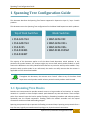
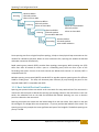
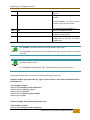
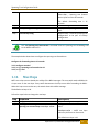
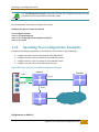
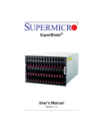
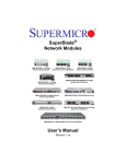
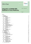
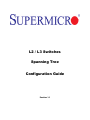
L2 / L3 Switches
Spanning Tree
Configuration Guide
Revision 1.1
Spanning TreeConfiguration Guide
The information in this USER’S MANUAL has been carefully reviewed and is believed to be accurate. The vendor
assumes no responsibility for any inaccuracies that may be contained in this document, makes no commitment to
update or to keep current the information in this manual, or to notify any person or organization of the updates.
Please Note: For the most up-to-date version of this manual, please see our web site at www.supermicro.com.
Super Micro Computer, Inc. (“Supermicro”) reserves the right to make changes to the product described in this
manual at any time and without notice. This product, including software, if any, and documentation may not, in
whole or in part, be copied, photocopied, reproduced, translated or reduced to any medium or machine without
prior written consent.
IN NO EVENT WILL SUPERMICRO BE LIABLE FOR DIRECT, INDIRECT, SPECIAL, INCIDENTAL, SPECULATIVE OR
CONSEQUENTIAL DAMAGES ARISING FROM THE USE OR INABILITY TO USE THIS PRODUCT OR DOCUMENTATION,
EVEN IF ADVISED OF THE POSSIBILITY OF SUCH DAMAGES. IN PARTICULAR, SUPERMICRO SHALL NOT HAVE
LIABILITY FOR ANY HARDWARE, SOFTWARE, OR DATA STORED OR USED WITH THE PRODUCT, INCLUDING THE
COSTS OF REPAIRING, REPLACING, INTEGRATING, INSTALLING OR RECOVERING SUCH HARDWARE, SOFTWARE, OR
DATA.
Any disputes arising between manufacturer and customer shall be governed by the laws of Santa Clara County in
the State of California, USA. The State of California, County of Santa Clara shall be the exclusive venue for the
resolution of any such disputes. Super Micro's total liability for all claims will not exceed the price paid for the
hardware product.
FCC Statement: This equipment has been tested and found to comply with the limits for a Class A digital device
pursuant to Part 15 of the FCC Rules. These limits are designed to provide reasonable protection against harmful
interference when the equipment is operated in a commercial environment. This equipment generates, uses, and
can radiate radio frequency energy and, if not installed and used in accordance with the manufacturer’s instruction
manual, may cause harmful interference with radio communications. Operation of this equipment in a residential
area is likely to cause harmful interference, in which case you will be required to correct the interference at your
own expense.
California Best Management Practices Regulations for Perchlorate Materials: This Perchlorate warning applies only
to products containing CR (Manganese Dioxide) Lithium coin cells. Perchlorate Material-special handling may
apply. See http://www.dtsc.ca.gov/hazardouswaste/perchlorate/ for further details.
Manual Revision 1.0
Release Date: February 24, 2013
Unless you request and receive written permission from Super Micro Computer, Inc., you may not copy any part of
this document.
Information in this document is subject to change without notice. Other products and companies referred to
herein are trademarks or registered trademarks of their respective companies or mark holders.
Copyright © 2013 by Super Micro Computer, Inc.
All rights reserved.
Printed in the United States of America
Supermicro L2/L3 Switches Configuration Guide
2
Spanning TreeConfiguration Guide
Contents
1
Spanning Tree Configuration Guide ...................................................................................................... 4
1.1
Spanning Tree Basics ..................................................................................................................... 4
1.1.1
Root Switch Election Procedure ............................................................................................ 6
1.2
Spanning Tree Support.................................................................................................................. 7
1.3
Spanning Tree Defaults ................................................................................................................. 7
1.4
Enabling / Disabling Spanning Tree............................................................................................... 8
1.4.1
Enable / Disable Spanning Tree Globally .............................................................................. 8
1.4.2
Enable / Disable Spanning Tree on Ports .............................................................................. 9
1.5
Configuring MST .......................................................................................................................... 10
1.5.1
Configuring MST region and instances ............................................................................... 11
1.6
Configuring RSTP ......................................................................................................................... 13
1.7
Spanning Tree Compatibility ....................................................................................................... 13
1.8
Configuring Root Switch (or) Priority .......................................................................................... 15
1.9
Port Priority ................................................................................................................................. 16
1.10
Path Cost ..................................................................................................................................... 18
1.11
Hello Time ................................................................................................................................... 20
1.12
Max Age ...................................................................................................................................... 22
1.13
Forwarding Time ......................................................................................................................... 23
1.14
Max Hops .................................................................................................................................... 24
1.15
Path Cost Long / Short ................................................................................................................ 25
1.16
Transmit Hold Count ................................................................................................................... 26
1.17
Root Guard .................................................................................................................................. 27
1.18
Topology Change Guard.............................................................................................................. 28
1.19
Port Fast ...................................................................................................................................... 30
1.20
Auto Edge .................................................................................................................................... 31
1.21
Link Type ..................................................................................................................................... 32
1.22
Spanning Tree Configuration Examples ...................................................................................... 34
Supermicro L2/L3 Switches Configuration Guide
3
Spanning TreeConfiguration Guide
1 Spanning Tree Configuration Guide
This document describes the Spanning Tree feature supported in Supermicro Layer 2 / Layer 3 switch
products.
This document covers the Spanning Tree configurations for the below listed Supermicro switch products.
Top of Rack Switches
Blade Switches
• SSE-G24-TG4
• SSE-G48-TG4
• SSE-X24S
• SSE-X3348S
• SSE-X3348T
• SBM-GEM-X2C
• SBM-GEM-X2C+
• SBM-GEM-X3S+
• SBM-XEM-X10SM
The majority of this document applies to all the above listed Supermicro switch products. In any
particular sub section however, the contents might vary across these switch product models. In those
sections the differences are clearly identified with reference to particular switch product models. If any
particular switch product model is not referenced, the reader can safely assume that the content is
applicable to all the above listed models.
Throughout this document, the common term “switch” refers to any of the above listed
Supermicro switch product models unless a particular switch product model is noted.
1.1 Spanning Tree Basics
Switches are interconnected to provide network access to a large number of end stations. In complex
networks it is possible to have multiple network paths between any two end devices. These multiple
paths form network loops that lead to packet flooding by forwarding broadcast and multicast packets
repeatedly over the looped connections. Flooding makes the network unusable until the looped
connections are disconnected and flooding stopped.
Spanning tree protocols help to prevent the flooding on network loops. Spanning tree protocols form a
loop-free tree, logically structured network topology over physical network connections.
Supermicro L2/L3 Switches Configuration Guide
4
Spanning TreeConfiguration Guide
Spanning tree enabled switches exchange spanning tree protocol messages (BPDU) to form a loop-free
topology. Based on the exchanged BPDU information, the spanning tree algorithm selects one of the
switches on the network as the root switch for the tree topology. All other switches on the network
choose a best loop free path to reach the root switch. The redundant paths to root switch are then
blocked to form a loop-free topology.
The spanning tree algorithm assigns one of the following roles to every port on the switches.
Root Port
Designated Port
Alternate Port
Blocked Port
•Port to reach the root switch with lowest path cost
•Root ports forward the traffic
•Loop-free connection to the other switch on the LAN
• Designated ports forward the traffic
• Redundant path to the root switch
•Alternate ports do not forward the traffic
•Redundant path to other switches on the LAN
•Blocked ports do not forward the traffic
When a network connection status changes, spanning tree recalculates the paths to form a loop-free
topology. Spanning tree calculations are based on the following three key factors:
Bridge Identifier: Combination of a switch’s MAC address and switch’s spanning tree priority
Path Cost: Spanning tree path cost to the root switch
Port Identifier: Combination of port number and port priority
When a switch boots up, it assumes its role as the root switch. It sends out spanning tree BPDUs with its
bridge id as the root bridge id. When a switch receives spanning tree BPDUs, it compares the received
BPDU information. If the received BPDU information is superior, the switch uses the received BPDU
information to determine the root bridge and recalculates the spanning tree. If the received BPDU
information is inferior, the switch ignores the received BPDU.
Spanning tree operates the switch ports in different states while calculating the loop-free topology.
BPDU exchanges between switches take a few seconds in a large LAN. To avoid any temporary loops
while forming spanning tree topology, the switch ports are moved through different states to reach a
forwarding state. Switch ports stay in one of the following spanning tree states:
Supermicro L2/L3 Switches Configuration Guide
5
Spanning TreeConfiguration Guide
Blocking
•Receives BPDUs
•Discards packets
•Does not learn MAC
Listening
Disabled
•Receives BPDUs
•Discards packets
•Does not learn MAC
Learning
•Receives BPDUs
•Discards packets
•Learns MAC addresses
Forwarding
•Does not receive BPDUs
•Discards packets
•Does not learn MAC
•Receives BPDUs
•Forwards packets
•Learns MAC addresses
Since spanning tree forms a logical loop-free topology, it helps to have physical loop connections on the
network for redundancy purposes. When an active connection fails, spanning tree enables the blocked
redundant connection automatically.
Rapid spanning tree protocol (RSTP) provides faster topology convergence. While spanning tree (STP)
takes more than 30 seconds to move a port to a forwarding state, RSTP can move a port to the
forwarding state within 3 times of the hello interval (the default hello interval is 2 seconds). RSTP is
compatible with STP.
Multiple spanning tree protocol (MSTP) extends RSTP to provide separate spanning trees for different
VLANs or VLAN groups. This helps use alternate paths efficiently by only blocking the ports for the
required VLANs. MSTP is compatible with RSTP.
1.1.1 Root Switch Election Procedure
Spanning tree protocol selects one switch as the root switch for every switched LAN. This root switch is
used as the reference point to decide the spanning tree topology. Based on the connections to this root
switch, the redundant links on the LAN are identified and blocked. Spanning tree runs an election
process to determine the root switch.
Spanning tree selects the switch with the lowest bridge ID as the root switch. Every switch on the LAN
has a bridge ID. The bridge ID has two components – its priority and the MAC address of the switch. The
spanning tree priority occupies the most significant two bytes of the bridge ID. The default spanning tree
priority is 32768.
Supermicro L2/L3 Switches Configuration Guide
6
Spanning TreeConfiguration Guide
STP Priority - 2 bytes
Switch MAC – 6 bytes
(Default 32768)
Bridge ID
When a switch starts spanning tree it sends out BPDUs with its bridge ID as the root bridge ID. When a
switch receives the BDPUs, it compares the received root bridge ID with its own bridge ID. If the
received root bridge ID is lower than its own bridge ID, the received switch accepts the other switch as
the root switch. If the received root bridge ID is higher than its own bridge ID, the received switch
ignores the received BPDU and continue to act as the root switch.
If the priorities of all switches are the same, the switch MAC addresses decide the lowest bridge ID and
hence the switch with the lowest MAC address will be elected as the root switch.
1.2 Spanning Tree Support
Supermicro switches support STP, RSTP and MSTP protocols based on standards IEEE 802.1D 2004 and
802.1s.
1.3 Spanning Tree Defaults
Parameter
Default Value
Spanning tree global status
Spanning tree port status
Spanning tree mode
Switch priority
Port priority
Port cost
Enabled
Enabled
MST
32768
128
Port Speed
Hello time
Forwarding time
Maximum aging time
Transmit hold count
Max hops
Path cost method
10 Mbps
100 Mbps
1 Gbps
10 Gbps
40 Gbps
2 seconds
15 seconds
20 seconds
3
20
long
Default
Cost
Path
2000000
200000
20000
2000
500
Supermicro L2/L3 Switches Configuration Guide
7
Spanning TreeConfiguration Guide
MST region name
MST region revision
Spanning tree compatibility
Root guard
Topology change guard
Port fast
Auto edge
Link type
Switch MAC address
0
In MSTP mode, the default
compatibility is MSTP and in RSTP
mode the default compatibility is
RSTP
Disabled
Disabled
Disabled
Enabled
Full duplex ports – point to point links
Half duplex ports – shared LAN links
1.4 Enabling / Disabling Spanning Tree
1.4.1 Enable / Disable Spanning Tree Globally
Spanning tree is enabled by default in Supermicro switches globally.
Follow the steps below to disable the spanning tree globally.
Step
Command
Description
Step 1
Step 2
configure terminal
no spanning-tree
Enters the configuration mode
Disables the spanning tree globally
Step 3
Step 4
end
show spanning-tree
Exits the configuration mode.
Displays the spanning tree information.
Step 5
write startup-config
Optional step – saves this spanning tree
configuration to be part of startup
configuration.
The “spanning-tree” command enables the spanning tree globally.
The examples below show ways to disable / enable the spanning tree function on Supermicro switches.
Disable the spanning tree.
SMIS# configure terminal
SMIS(config)# no spanning-tree
Supermicro L2/L3 Switches Configuration Guide
8
Spanning TreeConfiguration Guide
SMIS(config)# end
Enable the spanning tree.
SMIS# configure terminal
SMIS(config)# spanning-tree
SMIS(config)# end
1.4.2 Enable / Disable Spanning Tree on Ports
Spanning tree is enabled by default on all the ports and port channels in Supermicro switches.
Follow the steps below to disable the spanning tree on ports.
Step
Command
Description
Step 1
Step 2
configure terminal
interface <interface-type> <interface-id>
or
interface range <interface-type> <interface-id>
….
Enters the configuration mode
Enters the port interface mode.
interface-type – may be any of the
following:
gigabit-ethernet – gi
extreme-ethernet – ex
qx-ethernet – qx
port-channel – po
interface-id is in slot/port format for all
physical interfaces. It may be the port
channel identifier for port channel
interfaces.
Step 3
To disable the spanning tree in RST mode:
spanning-tree disable
To disable the default MST instance spanning tree:
spanning-tree disable
To configure multiple interfaces, use
the “interface range …” command. To
provide a range use a hypen (-)
between the start and end interface
numbers.
E.g.: int range gi 0/1-10
To provide multiple interfaces or
ranges, separate with a comma (,).
E.g.: int range gi 0/1-10, gi 0/20
Disables the spanning tree on the port.
instance-id – The MST instance
identifier may be from 1 to 16.
To disable the particular MST instance spanning
Supermicro L2/L3 Switches Configuration Guide
9
Spanning TreeConfiguration Guide
Step 4
Step 5
tree.
spanning-tree mst <instance-id> disable
end
Exits the configuration mode.
show spanning-tree interface <interface-type> Displays the spanning tree
information.
<interface-id>
port
show running-config interface <interface-type>
<interface-id>
Step 6
write startup-config
Optional step – saves this spanning tree
configuration to be part of startup
configuration.
“no spanning-tree disable” command enables the spanning tree on ports.
The examples below show various ways to disable / enable the spanning tree on ports.
Disable the spanning tree on ports ex 0/1 and ex 0/2.
SMIS# configure terminal
SMIS(config)# interface range ex 0/1-2
SMIS(config-if)# spanning-tree disable
SMIS(config)# end
Enable the spanning tree on port ex 0/1.
SMIS# configure terminal
SMIS(config)# interface ex 0/1
SMIS(config-if)# no spanning-tree disable
SMIS(config)# end
1.5 Configuring MST
Spanning tree is enabled by default in MST mode in Supermicro switches.
In case the switch was earlier configured in RST mode, follow the steps below to change to MST mode.
Step
Command
Description
Step 1
Step 2
configure terminal
spanning-tree mode mst
Enters the configuration mode
Configures the switch to operate in
MST mode.
Supermicro L2/L3 Switches Configuration Guide
10
Spanning TreeConfiguration Guide
Step 3
Step 4
end
show spanning-tree
Step 5
write startup-config
Exits the configuration mode.
Displays the spanning tree mode
information.
Optional step – saves this spanning tree
configuration to be part of startup
configuration.
Changing the spanning tree mode will shut down the currently running spanning tree and
restart it in the new given mode.
1.5.1 Configuring MST region and instances
All the spanning tree switches in an MST region must have the same values configured for the following
parameters.
•
•
•
Region name
Revision number
Instance to VLAN mapping
Follow the steps below to configure the MST region parameters.
Step
Command
Description
Step 1
Step 2
Step 3
configure terminal
spanning-tree mst configuration
instance <instance-id(1-16)> vlan <vlan-range>
Enters the configuration mode
Enters the MST configuration mode
Creates an MST instance and maps it to
the given VLAN range.
instance-id – The MST instance
identifier may be from 1 to 16.
Step 4
name <name-string>
vlan-range – may be any VLAN number
or list of VLAN numbers. Multiple VLAN
numbers can be provided as commaseparated values. Consecutive VLAN
numbers can be provided as a range,
such as 5-10.
User can configure VLANs with
identifiers 1 to 4069.
Configures the MST region name.
name-string – Alphanumeric case
sensitive string with maximum length of
32 characters.
Supermicro L2/L3 Switches Configuration Guide
11
Spanning TreeConfiguration Guide
Step 5
The default name is the system MAC
address.
Configures the MST region revision
number.
revision <revision-number>
revision-number – The MST revision
number may be from 0 to 65535.
Step 6
Step 7
end
show spanning-tree mst configuration
Step 8
write startup-config
The default revision-number is 0.
Exits the configuration mode.
Displays the spanning tree MST
configuration parameters.
Optional step – saves this spanning tree
configuration to be part of startup
configuration.
The “no name” command removes the configured MST region name.
The “no revision” command resets the configured MST region revision number to its default
value of 0.
The “no instance <instance-id(1-16)> vlan <vlan-range>” command removes the VLANs
from a given MST instance.
The “no instance <instance-id(1-16)>” command deletes the given MST instance.
The examples below show various ways to configure MST region parameters.
Configure the MST region with name dc1_region, revision number 1 and map the VLANs 100 to 300 to
MST instance 10.
SMIS# configure terminal
SMIS(config)# spanning-tree mst configuration
SMIS(config-mst)# name dc1_region
SMIS(config-mst)# revision 1
SMIS(config-mst)# instance 10 vlan 100-300
SMIS(config-mst)# end
Remove the VLANs 201 to 250 from MST instance 10.
SMIS# configure terminal
SMIS(config)# spanning-tree mst configuration
Supermicro L2/L3 Switches Configuration Guide
12
Spanning TreeConfiguration Guide
SMIS(config-mst)# no instance 10 vlan 201-250
SMIS(config-mst)# end
Delete the MST instance 10.
SMIS# configure terminal
SMIS(config)# spanning-tree mst configuration
SMIS(config-mst)# no instance 10
SMIS(config-mst)# end
1.6 Configuring RSTP
Spanning tree is enabled by default in MST mode in Supermicro switches.
Follow the steps below to change to RSTP.
Step
Command
Description
Step 1
Step 2
configure terminal
spanning-tree mode rst
Step 3
Step 4
end
show spanning-tree
Step 5
write startup-config
Enters the configuration mode
Configures the switch to operate in
RSTP mode.
Exits the configuration mode.
Displays the spanning tree mode
information.
Optional step – saves this spanning tree
configuration to be part of startup
configuration.
Changing the spanning tree mode will shut down the currently running spanning tree and
restart it in the new given mode.
1.7 Spanning Tree Compatibility
MSTP is backward compatible with RSTP and STP. Similarly RSTP is backward compatible with STP.
When an MSTP operating switch detects an RSTP operating switch in any port, the MSTP switch will
downgrade to RSTP operating mode on that port.
Similarly when an MSTP or RSTP operating switch detects an STP operating switch in any port, the switch
will downgrade to STP operating mode on that port.
Supermicro L2/L3 Switches Configuration Guide
13
Spanning TreeConfiguration Guide
Users can force the switch to operate in any particular compatibility mode. In user configured STP
compatible mode, switches will transmit and receive only STP BPDUs and will drop any RSTP and MSTP
BPDUS received.
In MSTP mode, the default compatibility is MSTP and in RSTP mode the default compatibility is RSTP.
Follow the steps below to configure the spanning tree compatibility.
Step
Command
Description
Step 1
Step 2
configure terminal
To force the spanning tree compatibility as STP
spanning-tree compatibility stp
Enters the configuration mode
Configures
the
spanning
compatibility.
tree
To force the spanning tree compatibility as RSTP
spanning-tree compatibility rst
Step 3
Step 4
To force the spanning tree compatibility as MSTP
spanning-tree compatibility mst
end
show spanning-tree
Step 5
write startup-config
Exits the configuration mode.
Displays the spanning tree mode
information.
Optional step – saves this spanning tree
configuration to be part of startup
configuration.
The “no spanning-tree compatibility” command resets the spanning tree compatibility
mode to the default value.
The examples below show various ways to configure the spanning tree compatibility.
Configure the spanning tree compatibility as STP.
SMIS# configure terminal
SMIS(config)# spanning-tree compatibility stp
SMIS(config)# end
Configure the spanning tree compatibility as RSTP.
SMIS# configure terminal
SMIS(config)# spanning-tree compatibility rst
SMIS(config)# end
Supermicro L2/L3 Switches Configuration Guide
14
Spanning TreeConfiguration Guide
1.8 Configuring Root Switch (or) Priority
The switch with the lowest priority value gets elected as the root switch. To define any particular switch
as the root switch, assign it a lower numeric priority value. The default spanning tree priority is 32768.
When the priorities of all switches are the same, the switch with the lowest MAC address gets elected as
the root switch.
Follow the steps below to change the spanning tree priority.
Step
Command
Step 1
Step 2
configure terminal
To configure the switch priority in RST mode:
spanning-tree priority <priority-value>
Description
Enters the configuration mode
Configures the switch spanning tree
priority.
priority-value – Spanning tree switch
To configure the switch priority for the default MST priority value in multiples of 4096 from
instance 0:
0 to 61440. In other words, only the
spanning-tree priority <priority-value>
following priority values are valid.
To configure the switch priority for a particular MST
instance:
spanning-tree mst <instance-id> priority <priorityvalue>
0
16384
32768
49152
4096
20480
36864
53248
8192
24576
40960
57344
12288
28672
45056
61440
The default priority value is 32768.
Step 3
Step 4
end
show spanning-tree bridge priority
Step 5
show spanning-tree
write startup-config
instance-id – The MST instance
identifier may be from 1 to 16.
Exits the configuration mode.
Displays
the
spanning
tree
configuration parameters including the
switch priority values.
Optional step – saves this spanning tree
configuration to be part of startup
configuration.
The “no spanning-tree priority” command resets the spanning tree switch priority to the
default value of 32768. In MST mode, it resets the switch priority for the default MST
instance to 0.
The “no spanning-tree mst <instance-id> priority” command resets the spanning tree
switch priority to the default value of 32768 for the given MST instance.
The examples below show various ways to configure the spanning tree switch priority.
Supermicro L2/L3 Switches Configuration Guide
15
Spanning TreeConfiguration Guide
Configure the spanning tree switch priority as 4096 in RST mode.
SMIS# configure terminal
SMIS(config)# spanning-tree priority 4096
SMIS(config)# end
Configure the spanning tree switch priority as 4096 for the default MST instance 0.
SMIS# configure terminal
SMIS(config)# spanning-tree priority 4096
SMIS(config)# end
Configure the spanning tree switch priority as 4096 for the MST instance 10.
SMIS# configure terminal
SMIS(config)# spanning-tree mst 10 priority 4096
SMIS(config)# end
1.9 Port Priority
When the spanning tree detects that multiple paths to the root switch are in a loop condition, it selects
the port with lowest path cost as the forwarding port. In case of multiple ports having the same path
cost to the root switch, spanning tree selects the port with the lowest numeric port priority value as the
forwarding port.
When the priorities of all the ports are the same, the port with lowest port identifier gets selected as the
forwarding port.
Follow the steps below to change the spanning tree port priority.
Step
Command
Description
Step 1
Step 2
configure terminal
interface <interface-type> <interface-id>
or
interface range <interface-type> <interface-id>
….
Enters the configuration mode
Enters the port interface mode.
interface-type – may be any of the
following:
gigabitethernet – gi
extreme-ethernet – ex
qx-ethernet – qx
port-channel – po
interface-id is in slot/port format for all
physical interfaces. It may be the port
channel identifier for port channel
interfaces.
Supermicro L2/L3 Switches Configuration Guide
16
Spanning TreeConfiguration Guide
Step 3
Step 4
Step 5
Step 6
To configure multiple interfaces, use
the “interface range …” command. To
provide a range, use a hypen (-)
between the start and end interface
numbers.
E.g.: int range gi 0/1-10
To provide multiple interfaces or
ranges, separate with a comma (,).
E.g.: int range gi 0/1-10, gi 0/20
To configure the port priority in RST mode:
Configures the port spanning tree
spanning-tree port-priority <priority-value>
priority.
priority-value – Spanning tree port
To configure the port priority for the default MST priority value may be from 0 to 240.
instance 0:
Priority value must be a multiple of 16.
spanning-tree port-priority <priority-value>
The default priority value is 128.
To configure the port priority for a particular MST
instance:
instance-id – The MST instance
spanning-tree mst <instance-id> port-priority identifier may be from 1 to 16.
<priority-value>
end
Exits the configuration mode.
show spanning-tree interface <interface-type> Displays the spanning tree port
parameters including the port priority
<interface-id>
values.
write startup-config
Optional step – saves this spanning tree
configuration to be part of startup
configuration.
The “no spanning-tree port-priority” command resets the spanning tree port priority to the
default value of 128. In MST mode, it resets the port priority for the default MST instance to
0.
The “no spanning-tree mst <instance-id> port-priority” command resets the spanning tree
port priority to the default value of 128 for the given MST instance.
The examples below show various ways to configure the spanning tree port priority.
Configure the spanning tree port priority as 208 in RST mode on the ports ex 0/1 and ex 0/2.
SMIS# configure terminal
SMIS(config)# interface range ex 0/1-2
SMIS(config-if)# spanning-tree port-priority 208
SMIS(config-if)# end
Supermicro L2/L3 Switches Configuration Guide
17
Spanning TreeConfiguration Guide
Configure the spanning tree port priority as 112 for the default MST instance 0 on the port gi 0/1
SMIS# configure terminal
SMIS(config)# interface gi 0/1
SMIS(config-if)# spanning-tree port-priority 112
SMIS(config-if)# end
Configure the spanning tree port priority as 64 for the MST instance 10 on the port ex 0/1
SMIS# configure terminal
SMIS(config)# interface ex 0/1
SMIS(config-if)# spanning-tree mst 10 port-priority 64
SMIS(config-if)# end
1.10
Path Cost
When spanning tree detects that multiple paths to the root switch are in a loop condition, it selects the
port with lowest path cost as the forwarding port. In case of multiple ports having the same path cost to
the root switch, spanning tree selects the port with lowest numeric port priority value as the forwarding
port.
The default path cost for the ports are calculated based on the port speed. The table below shows the
default path costs for different speed.
Port Speed
Default Path Cost
10 Mbps
100 Mbps
1 Gbps
10 Gbps
40 Gbps
2000000
200000
20000
2000
500
Follow the steps below to change the spanning tree path cost for ports.
Step
Command
Description
Step 1
Step 2
configure terminal
interface <interface-type> <interface-id>
or
interface range <interface-type> <interface-id>
….
Enters the configuration mode
Enters the port interface mode.
interface-type – may be any of the
following:
gigabitethernet – gi
extreme-ethernet – ex
qx-ethernet – qx
port-channel – po
Supermicro L2/L3 Switches Configuration Guide
18
Spanning TreeConfiguration Guide
interface-id is in slot/port format for all
physical interfaces. It may be the port
channel identifier for port channel
interfaces.
Step 3
Step 4
Step 5
Step 6
To configure multiple interfaces, use
the “interface range …” command. To
provide a range use a hypen (-)
between the start and end interface
numbers.
E.g.: int range gi 0/1-10
To provide multiple interfaces or
ranges, use separate with a comma (,).
E.g.: int range gi 0/1-10, gi 0/20
To configure the port priority in RST mode:
Configures the port spanning tree path
spanning-tree cost <cost-value>
cost.
cost-value – Spanning tree port
To configure the port priority for the default MST priority value may be from 0 to
instance 0:
200000000.
spanning-tree cost <cost-value>
The default path cost is calculated
To configure the port priority for a particular MST based on the port speed.
instance:
spanning-tree mst <instance-id> cost <cost- instance-id – The MST instance
value>
identifier may be from 1 to 16.
end
Exits the configuration mode.
show spanning-tree interface <interface-type> Displays the spanning tree port
parameters including the port path cost
<interface-id>
values.
write startup-config
Optional step – saves this spanning tree
configuration to be part of startup
configuration.
The “no spanning-tree cost” command resets the spanning tree port path cost to the
default value. In MST mode, it resets the port path cost for the default MST instance to 0.
The “no spanning-tree mst <instance-id> cost” command resets the spanning tree port
path cost to the default value for the given MST instance.
The examples below show various ways to configure the spanning tree port path cost.
Configure the spanning tree port path cost as 200 in RST mode on ports ex 0/1 and ex 0/2.
SMIS# configure terminal
Supermicro L2/L3 Switches Configuration Guide
19
Spanning TreeConfiguration Guide
SMIS(config)# interface range ex 0/1-2
SMIS(config-if)# spanning-tree cost 200
SMIS(config-if)# end
Configure the spanning tree port priority as 200 for the default MST instance of 0 on port gi 0/1
SMIS# configure terminal
SMIS(config)# interface gi 0/1
SMIS(config-if)# spanning-tree cost 200
SMIS(config-if)# end
Configure the spanning tree port priority as 20 for the MST instance 10 on port ex 0/1
SMIS# configure terminal
SMIS(config)# interface ex 0/1
SMIS(config-if)# spanning-tree mst 10 cost 20
SMIS(config-if)# end
1.11
Hello Time
The root switch periodically sends the BPDU messages on every port for every hello time interval.
The default hello time is 2 seconds.
If switches do not receive BPDU messages for a period of 3 hello time intervals, spanning tree protocol
assumes the root switch has failed.
In MSTP, the hello time is configurable on individual ports. In RSTP, the hello time is configured
commonly for all the ports.
Follow the steps below to change the hello time for RSTP.
Step
Command
Description
Step 1
Step 2
configure terminal
To configure the hello time in RST mode:
spanning-tree hello-time <time-value>
Enters the configuration mode
Configures the hello time interval.
time-value – Hello time value may be 1
or 2 seconds.
Step 3
Step 4
Step 5
The default hello time is 2 seconds.
end
Exits the configuration mode.
show spanning-tree interface <interface-type> Displays the spanning tree port
parameters including the hello time
<interface-id>
values.
write startup-config
Optional step – saves this spanning tree
Supermicro L2/L3 Switches Configuration Guide
20
Spanning TreeConfiguration Guide
configuration to be part of startup
configuration.
The “no spanning-tree hello-time” command resets the spanning tree port hello time to the
default value of 2 seconds.
Follow the steps below to change the hello time for ports in MSTP.
Step
Command
Description
Step 1
Step 2
configure terminal
interface <interface-type> <interface-id>
or
interface range <interface-type> <interface-id>
….
Enters the configuration mode
Enters the port interface mode.
interface-type – may be any of the
following:
gigabitethernet – gi
extreme-ethernet – ex
qx-ethernet – qx
port-channel – po
interface-id is in slot/port format for all
physical interfaces. It may be the port
channel identifier for port channel
interfaces.
Step 3
To configure the hello time in MST mode:
spanning-tree mst hello-time <time-value>
To configure multiple interfaces, use
the “interface range …” command. To
provide a range use a hyphen (-)
between the start and end interface
numbers.
E.g.: int range gi 0/1-10
To provide multiple interfaces or
ranges, separate with a comma (,).
E.g.: int range gi 0/1-10, gi 0/20
Configures the hello time interval.
time-value – Hello time value may be 1
or 2 seconds.
Step 4
Step 5
Step 6
end
show spanning-tree bridge hello-time
write startup-config
The default hello time is 2 seconds.
Exits the configuration mode.
Displays the spanning tree hello time.
Optional step – saves this spanning tree
configuration to be part of startup
configuration.
Supermicro L2/L3 Switches Configuration Guide
21
Spanning TreeConfiguration Guide
The “no spanning-tree mst hello-time” command resets the spanning tree port hello time
to the default value of 2 seconds.
The examples below show various ways to configure the spanning tree port hello time.
Configure the spanning tree port hello time as 1 second in RST mode.
SMIS# configure terminal
SMIS(config)# spanning-tree hello-time 1
SMIS(config)# end
Configure the MSTP hello time as 1 second for port gi 0/1
SMIS# configure terminal
SMIS(config)# interface gi 0/1
SMIS(config-if)# spanning-tree mst hello-time 1
SMIS(config-if)# end
1.12
Max Age
Switches maintain the BPDU information for every port for a maximum age period. If BPDU
configuration messages are not received on any ports within the max age time, the switch will
reconfigure those ports.
Max age time affects failure detection and reconfiguration. A smaller max age time will help detect
failures quickly. It is advisable to choose a max age time based on the maximum number of switches on
the network between any two hosts.
The default max age time is 20 seconds.
The max age value should be less than twice of (forward time – 1).
Follow the steps below to change the max age time.
Step
Command
Description
Step 1
Step 2
configure terminal
To configure the max age time:
spanning-tree max-age <age-value>
Enters the configuration mode
Configures the switch spanning tree
max age time.
Supermicro L2/L3 Switches Configuration Guide
22
Spanning TreeConfiguration Guide
age-value – Spanning tree max age
value may be from 6 to 40 seconds.
Step 3
Step 4
end
show spanning-tree bridge max-age
Step 5
show spanning-tree
write startup-config
The default max age is 20.
Exits the configuration mode.
Displays
the
spanning
tree
configuration parameters including the
switch priority values.
Optional step – saves this spanning tree
configuration to be part of startup
configuration.
The “no spanning-tree max-age” command resets the spanning tree max age to the default
value of 20.
The example below shows how to configure the spanning tree max age.
Configure the max age as 12.
SMIS# configure terminal
SMIS(config)# spanning-tree max-age 12
SMIS(config)# end
1.13
Forwarding Time
A switch will wait for the of forwarding time interval on listening and learning states before going to a
forwarding state.
The default forwarding time is 15 seconds. Hence, a switch waits for 15 seconds in the listening state
and for another 15 seconds in the learning state before going to the forwarding state.
The forwarding time value should maintain the following relation with max age:
2*(Forward Time -1) >= Max Age
Follow the steps below to change the forwarding time.
Step
Command
Description
Step 1
Step 2
configure terminal
To configure the max age time:
spanning-tree forward-time <time-value>
Enters the configuration mode
Configures the switch spanning tree
max age time.
Supermicro L2/L3 Switches Configuration Guide
23
Spanning TreeConfiguration Guide
time-value – Spanning tree forward
time may be from 4 to 30 seconds.
Step 3
Step 4
end
show spanning-tree bridge forward-time
Step 5
write startup-config
The default forwarding time is 15
seconds.
Exits the configuration mode.
Displays the spanning tree forward
time.
Optional step – saves this spanning tree
configuration to be part of startup
configuration.
The “no spanning-tree forward-time” command resets the spanning tree forwarding time
to the default value of 15.
The example below shows how to configure the spanning tree forward time.
Configure the forwarding time as 12 seconds.
SMIS# configure terminal
SMIS(config)# spanning-tree forward-time 12
SMIS(config)# end
1.14
Max Hops
MSTP uses a hop count to decide the validity of the BPDU messages. The root switch sends a BPDU with
a hops count as the max hops. Every switch decrements the hops count while forwarding the BPDU.
When this hops count reaches zero, the switch discards the BPDU message.
The default max hops is 20.
Follow the steps below to change the max hops.
Step
Command
Description
Step 1
Step 2
configure terminal
To configure the max age time:
spanning-tree mst max-hops <maxhops-value>
Enters the configuration mode
Configures the switch MSTP max hops
value.
maxhops-value – MSTP max hops
value may be from 6 to 40 seconds.
The default max hops is 20.
Supermicro L2/L3 Switches Configuration Guide
24
Spanning TreeConfiguration Guide
Step 3
Step 4
end
show spanning-tree mst
Step 5
write startup-config
Exits the configuration mode.
Displays the spanning tree max hops
along with other MST information.
Optional step – saves this spanning tree
configuration to be part of startup
configuration.
The “no spanning-tree mst max-hops” command resets the MST max hops to the default
value of 20.
The example below shows how to configure the MSTP max hops.
Configure the MST max hops as 30.
SMIS# configure terminal
SMIS(config)# spanning-tree mst max-hops 30
SMIS(config)# end
1.15
Path Cost Long / Short
Spanning tree was originally designed with 16-bit path costs. This was good enough for fast Ethernet and
Gigabit Ethernet speed links but not enough for 10Gb and higher speed ports. Hence, spanning tree
protocol introduced support for 32-bit path costs.
The 16-bit path costs method is referred to as the short path cost method and the 32-bit path cost
method is referred to as the long path costs method.
In MSTP and RSTP mode, Supermicro switches support long path costs by default. In STP compatible
RSTP mode, Supermicro switches uses short path costs by default.
Follow the steps below to change the path costs method.
Step
Command
Description
Step 1
Step 2
configure terminal
To configure the path cost method as short
Enters the configuration mode
Configures the path cost method.
spanning-tree pathcost method short
To configure the path cost method as long
In MSTP and RSTP, the default path cost
method is long. In STP compatible RSTP
mode, the default path cost is short.
spanning-tree pathcost method long
end
show spanning-tree pathcost method
Exits the configuration mode.
Displays the spanning tree path cost
Step 3
Step 4
Supermicro L2/L3 Switches Configuration Guide
25
Spanning TreeConfiguration Guide
Step 5
method information.
Optional step – saves this spanning tree
configuration to be part of startup
configuration.
write startup-config
The “no spanning-tree pathcost method” command resets the path cost method to the
default value.
The example below shows how to configure the path cost method.
Configure the path cost method as short.
SMIS# configure terminal
SMIS(config)# spanning-tree pathcost method short
SMIS(config)# end
1.16
Transmit Hold Count
Transmit hold count helps to control the BPDU burst traffic. A switch limits the number of BPDUs sent in
a second by the transmit hold count. A higher transmit hold count value allows switches to send more
BPDUs for faster convergence. However, this might lead to high switch CPU utilization.
The default transmit hold count is 3.
Follow the steps below to change the transmit hold count value.
Step
Command
Description
Step 1
Step 2
configure terminal
spanning-tree transmit hold-count <count_value>
Enters the configuration mode
Configures the transmit hold count
value.
Count-value – Transmit hold count
value may be from 1 to 10.
Step 3
Step 4
end
show spanning-tree detail
Step 5
write startup-config
The default transmit hold count value is
3.
Exits the configuration mode.
Displays the spanning tree hold count
information.
Optional step – saves this spanning tree
configuration to be part of startup
configuration.
Supermicro L2/L3 Switches Configuration Guide
26
Spanning TreeConfiguration Guide
The “no spanning-tree transmit hold-count” command resets the hold count to the default
value of 3.
The example below shows how to configure the transmit hold count value.
Configure the transmit hold count as 8.
SMIS# configure terminal
SMIS(config)# spanning-tree transmit hold-count 8
SMIS(config)# end
1.17
Root Guard
In spanning tree networks, the position of the root switch is important to achieve optimized topology.
According to spanning tree protocol, any switch can become a root switch based on its priority and
switch MAC address. Networks managed by multiple administrators can lead to multiple switches with
lowest priority competing to become the root switch. There is no option to block any switch becoming
the root switch to maintain an optimized topology.
The root guard feature helps prevent any unexpected switch from becoming the root switch. If the root
guard feature is enabled on a port, it prevents any switches connected to that port from becoming the
root switch. If any superior BPDU is received on the root guard enabled port, a switch moves that port
from the forwarding state to the listening state.
The root guard feature is disabled on all ports by default.
Follow the steps below to enable the root guard feature on the ports.
Step
Command
Description
Step 1
Step 2
configure terminal
interface <interface-type> <interface-id>
or
interface range <interface-type> <interface-id>
….
Enters the configuration mode
Enters the port interface mode.
interface-type – may be any of the
following:
gigabitethernet – gi
extreme-ethernet – ex
qx-ethernet – qx
port-channel – po
interface-id is in slot/port format for all
physical interfaces. It may be the port
channel identifier for port channel
interfaces.
Supermicro L2/L3 Switches Configuration Guide
27
Spanning TreeConfiguration Guide
Step 3
To configure multiple interfaces, use
the “interface range …” command. To
provide a range use a hyphen (-)
between the start and end interface
numbers.
E.g.: int range gi 0/1-10
To provide multiple interfaces or
ranges, separate with a comma (,).
E.g.: int range gi 0/1-10, gi 0/20
Enables the root guard feature.
spanning-tree restricted-role
Step 4
Step 5
end
show spanning-tree detail
Step 6
write startup-config
The default option is the root guard
feature being disabled.
Exits the configuration mode.
Displays the spanning tree root guard
information.
Optional step – saves this spanning tree
configuration to be part of startup
configuration.
The “no spanning-tree restricted-role” command resets the root guard feature to the
default value of disabled.
The example below shows how to enable the root guard feature.
Enable the root guard feature on ports ex 0/1 and ex 0/2.
SMIS# configure terminal
SMIS(config)# interface range ex 0/1-2
SMIS(config-if)# spanning-tree restricted-role
SMIS(config-if)# end
1.18
Topology Change Guard
The topology change guard feature helps to prevent unexpected topology changes. Network
administrators can configure the topology guard on ports that are not expected to receive topology
change BPDUs.
Topology change BPDUs received on the topology change guard enabled ports will be dropped.
The topology guard feature is disabled on all the ports by default.
Follow the steps below to enable the topology guard feature on the ports.
Supermicro L2/L3 Switches Configuration Guide
28
Spanning TreeConfiguration Guide
Step
Command
Description
Step 1
Step 2
configure terminal
interface <interface-type> <interface-id>
or
interface range <interface-type> <interface-id>
….
Enters the configuration mode
Enters the port interface mode.
interface-type – may be any of the
following:
gigabit-ethernet – gi
extreme-ethernet – ex
qx-ethernet – qx
port-channel – po
interface-id is in slot/port format for all
physical interfaces. It may be the port
channel identifier for port channel
interfaces.
Step 3
To configure multiple interfaces, use
the “interface range …” command. To
provide a range use a hyphen (-)
between the start and end interface
numbers.
E.g.: int range gi 0/1-10
To provide multiple interfaces or
ranges, separate with a comma (,).
E.g.: int range gi 0/1-10, gi 0/20
Enables the topology guard feature.
spanning-tree restricted-tcn
Step 4
Step 5
end
show spanning-tree detail
Step 6
write startup-config
The default option is the topology
guard feature being disabled.
Exits the configuration mode.
Displays the spanning tree topology
guard information.
Optional step – saves this spanning tree
configuration to be part of startup
configuration.
The “no spanning-tree restricted-tcn” command resets the topology guard feature to the
default value of disabled.
The example below shows how to enable the topology guard feature.
Enable the topology guard feature on ports ex 0/1 and ex 0/2.
SMIS# configure terminal
SMIS(config)# interface range ex 0/1-2
Supermicro L2/L3 Switches Configuration Guide
29
Spanning TreeConfiguration Guide
SMIS(config-if)# spanning-tree restricted-tcn
SMIS(config-if)# end
1.19
Port Fast
When a port link is up, spanning tree does not allow the port to forward the packets immediately.
Instead, it moves the port through listening and learning states before reaching the forwarding state.
This state machine function helps to achieve a loop free topology, but delays the port operations in
forwarding the traffic.
The switch ports connected to computers and servers are not expected to cause any loops. Those ports
can be configured with the port fast feature to start forwarding the traffic immediately instead of
waiting through the learning and listening states.
Configure the port fast feature only to the ports that are connected to computers and
servers. Configuring port fast on the ports that are connected to other switches might cause
network loops.
The port fast feature is disabled on all ports by default.
Follow the steps below to enable the port fast feature on the ports.
Step
Command
Description
Step 1
Step 2
configure terminal
interface <interface-type> <interface-id>
or
interface range <interface-type> <interface-id>
….
Enters the configuration mode
Enters the port interface mode.
interface-type – may be any of the
following:
gigabitethernet – gi
extreme-ethernet – ex
qx-ethernet – qx
port-channel – po
interface-id is in slot/port format for all
physical interfaces. It may be the port
channel identifier for port channel
interfaces.
To configure multiple interfaces, use
the “interface range …” command. To
provide a range use a hyphen (-)
between the start and end interface
numbers.
E.g.: int range gi 0/1-10
Supermicro L2/L3 Switches Configuration Guide
30
Spanning TreeConfiguration Guide
Step 3
To provide multiple interfaces or
ranges, separate with a comma (,).
E.g.: int range gi 0/1-10, gi 0/20
Enables the port fast feature.
spanning-tree portfast
Step 4
Step 5
end
show spanning-tree detail
Step 6
write startup-config
The default setting is the port fast
feature being disabled.
Exits the configuration mode.
Displays the spanning tree port fast
information.
Optional step – saves this spanning tree
configuration to be part of startup
configuration.
The “no spanning-tree portfast” command resets the port fast feature to the default value
of disabled.
The example below shows how to enable the port fast feature.
Enable the port fast feature on ports ex 0/1 and ex 0/2.
SMIS# configure terminal
SMIS(config)# interface range ex 0/1-2
SMIS(config-if)# spanning-tree portfast
SMIS(config-if)# end
1.20
Auto Edge
The auto edge feature helps to detect the other end of the device attached to the ports. If no BPDU is
received for a period of time on auto edge enabled ports, the switch marks those parts as edge ports
assuming those ports are not connected to other switches. This helps to move the port to the
forwarding state quickly. Also, switches do not send topology change notifications when an edge port’s
status changes.
The auto edge feature is enabled on all the ports by default.
Follow the steps below to configure the auto edge feature on the ports.
Step
Command
Description
Step 1
Step 2
configure terminal
Enters the configuration mode
interface <interface-type> <interface-id>
Enters the port interface mode.
or
interface range <interface-type> <interface-id> interface-type – may be any of the
Supermicro L2/L3 Switches Configuration Guide
31
Spanning TreeConfiguration Guide
….
following:
gigabit-ethernet – gi
extreme-ethernet – ex
qx-ethernet – qx
port-channel – po
interface-id is in slot/port format for all
physical interfaces. It may be the port
channel identifier for port channel
interfaces.
Step 3
To configure multiple interfaces, use
the “interface range …” command. To
provide a range use a hyphen (-)
between the start and end interface
numbers.
E.g.: int range gi 0/1-10
To provide multiple interfaces or
ranges, separate with a comma (,).
E.g.: int range gi 0/1-10, gi 0/20
Enables or disables the auto edge
feature.
To enable the auto-edge
spanning-tree auto-edge
Step 4
Step 5
To disable the auto-edge
no spanning-tree auto-edge
end
show spanning-tree detail
Step 6
write startup-config
The default setting is the auto edge
feature being enabled.
Exits the configuration mode.
Displays the spanning tree auto edge
information.
Optional step – saves this spanning tree
configuration to be part of startup
configuration.
The example below shows how to disable the auto edge feature.
Disable the auto edge feature on ports ex 0/1 and ex 0/2.
SMIS# configure terminal
SMIS(config)# interface range ex 0/1-2
SMIS(config-if)# no spanning-tree auto-edge
SMIS(config-if)# end
1.21
Link Type
Spanning tree decides the link type based on the duplex mode of the ports. It detects full duplex ports as
point to point links and half duplex ports as a shared LAN links.
Supermicro L2/L3 Switches Configuration Guide
32
Spanning TreeConfiguration Guide
The point to point links are assumed to be connected directly to another spanning tree switch. The
shared LAN links are assumed to be connected to multiple switches through hubs.
In point to point links, spanning tree negotiates with other end switches to move the ports rapidly to the
forwarding state.
Users can override the type of ports as either point to point links or as shared links.
Follow the steps below to configure the link type of the ports.
Step
Command
Description
Step 1
Step 2
configure terminal
interface <interface-type> <interface-id>
or
interface range <interface-type> <interface-id>
….
Enters the configuration mode
Enters the port interface mode.
interface-type – may be any of the
following:
gigabit-ethernet – gi
extreme-ethernet – ex
qx-ethernet – qx
port-channel – po
interface-id is in slot/port format for all
physical interfaces. It may be the port
channel identifier for port channel
interfaces.
Step 3
To configure the link type as point to point
spanning-tree link-type point-to-point
Step 4
Step 5
To configure the link type as shared
spanning-tree link-type shared
end
show spanning-tree detail
Step 6
write startup-config
To configure multiple interfaces, use
the “interface range …” command. To
provide a range use a hyphen (-)
between the start and end interface
numbers.
E.g.: int range gi 0/1-10
To provide multiple interfaces or
ranges, separate with a comma (,).
E.g.: int range gi 0/1-10, gi 0/20
Configures the link type.
Exits the configuration mode.
Displays the spanning tree auto edge
information.
Optional step – saves this spanning tree
configuration to be part of startup
configuration.
Supermicro L2/L3 Switches Configuration Guide
33
Spanning TreeConfiguration Guide
The “no spanning-tree link-type” command resets the user configured link type to let the
switch detect the link type based on the duplex mode.
The example below shows how to configure the link type.
Configure port gi 0/1 as a point to point link.
SMIS# configure terminal
SMIS(config)# interface gi 0/1
SMIS(config-if)# spanning-tree link-type point-to-point
SMIS(config-if)# end
1.22
Spanning Tree Configuration Examples
Configure the following requirements on the switches as shown below in Figure MSTP-Eg.1.
1.
2.
3.
4.
Configure two MST instances separately for VLAN 100 and 200.
Configure switch B as the root switch for the VLAN 100 instance.
Configure switch C as the root switch for the VLAN 200 instance.
Configure port gi 0/1-40 in all the switches as port fast.
Figure MSTP-Eg.1 Spanning Tree MSTP Configuration Example
Switch A
Switch B
Gi 0/1
Ex 0/2
Gi 0/40
Ex 0/1
Switch C
Configurations on Switch A
Supermicro L2/L3 Switches Configuration Guide
34
Spanning TreeConfiguration Guide
SMIS# configure terminal
# Create VLANs 100 and 200
SMIS(config)# vlan 100,200
SMIS(config-vlan)# exit
# Create MST instance for VLANs 100 and 200
SMIS(config)# spanning-tree mst configuration
SMIS(config-mst)# instance 1 vlan 100
SMIS(config-mst)# instance 2 vlan 200
SMIS(config-mst)# exit
# Configure port gi 0/1-40 as port fast
SMIS(config)# interface range gi 0/1-40
SMIS(config-if)# spanning-tree portfast
Warning: portfast should only be enabled on ports connected to a single host.
Connecting hubs, concentrators, switches, bridges, etc. to this interface
when portfast is enabled can cause temporary bridging loops.
Use with CAUTION
SMIS(config-if)# exit
# Save this spanning tree configuration.
SMIS# write startup-config
Building configuration, Please wait. May take a few minutes ...
[OK]
SMIS#
Configurations on Switch B
SMIS# configure terminal
# Create VLANs 100 and 200
SMIS(config)# vlan 100,200
SMIS(config-vlan)# exit
# Create MST instance for VLANs 100 and 200
SMIS(config)# spanning-tree mst configuration
SMIS(config-mst)# instance 1 vlan 100
SMIS(config-mst)# instance 2 vlan 200
SMIS(config-mst)# exit
# Configure port gi 0/1-40 as port fast
SMIS(config)# interface range gi 0/1-40
SMIS(config-if)# spanning-tree portfast
Warning: portfast should only be enabled on ports connected to a single host.
Connecting hubs, concentrators, switches, bridges, etc. to this interface
when portfast is enabled can cause temporary bridging loops.
Use with CAUTION
Supermicro L2/L3 Switches Configuration Guide
35
Spanning TreeConfiguration Guide
SMIS(config-if)# exit
# Configure switch B as the root switch for the VLAN 100 instance
SMIS(config)# spanning-tree mst 1 priority 4096
SMIS(config)# end
# Check the spanning tree MST configurations
SMIS# show spanning-tree mst 1 detail
## MST01
VLANs mapped: 100
Bridge Address 00:30:48:a1:11:01 Priority 4096
Root
Address 00:30:48:a1:11:01 Priority 4096
Root
this switch for MST01
Gi0/47 of MST01 is Designated, Forwarding
Port info
port id 128.47
priority 128 cost 200000
Designated root address 00:30:48:a1:11:01 priority 4096 cost 0
Designated bridge address 00:30:48:a1:11:01 priority 4096 port id 128.47
SMIS#
# Save this spanning tree configuration.
SMIS# write startup-config
Building configuration, Please wait. May take a few minutes ...
[OK]
SMIS#
Configurations on Switch C
SMIS# configure terminal
# Create VLANs 100 and 200
SMIS(config)# vlan 100,200
SMIS(config-vlan)# exit
# Create MST instance for VLANs 100 and 200
SMIS(config)# spanning-tree mst configuration
SMIS(config-mst)# instance 1 vlan 100
SMIS(config-mst)# instance 2 vlan 200
SMIS(config-mst)# exit
# Configure port gi 0/1-40 as port fast
SMIS(config)# interface range gi 0/1-40
SMIS(config-if)# spanning-tree portfast
Warning: portfast should only be enabled on ports connected to a single host.
Connecting hubs, concentrators, switches, bridges, etc. to this interface
when portfast is enabled can cause temporary bridging loops.
Use with CAUTION
SMIS(config-if)# exit
Supermicro L2/L3 Switches Configuration Guide
36
Spanning TreeConfiguration Guide
# Configure switch C as the root switch for VLAN 200 instance
SMIS(config)# spanning-tree mst 2 priority 4096
SMIS(config)# end
# Check the spanning tree MST configurations
SMIS# show spanning-tree mst 2 detail
## MST02
Vlans mapped: 200
Bridge Address 00:30:48:e3:56:12 Priority 4096
Root
Address 00:30:48:e3:56:12 Priority 4096
Root
this switch for MST02
Gi0/47 of MST02 is Designated, Forwarding
Port info
port id 128.47
priority 128 cost 200000
Designated root address 00:30:48:e3:56:12 priority 4096 cost 0
Designated bridge address 00:30:48:e3:56:12 priority 4096 port id 128.47
SMIS#
# Save this spanning tree configuration.
SMIS# write startup-config
Building configuration, Please wait. May take a few minutes ...
[OK]
SMIS#
Supermicro L2/L3 Switches Configuration Guide
37