1
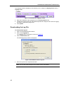
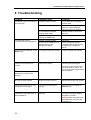
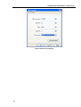
AvediaServer Administrator’s Guide AvediaServer Administrator’s Guide V3.0.1 Notices Disclaimer © Exterity Limited 2003-2009 The information contained in this document is subject to change without notice. This document contains information that is protected by copyright. Reproduction, adaptation, or translation without prior permission is prohibited, except as under the copyright laws. Document Reference 1300-0016-0001 EXTERITY LIMITED MAKES NO WARRANTY OF ANY KIND WITH REGARD TO THIS MATERIAL, INCLUDING, BUT NOT LIMITED TO, THE IMPLIED WARRANTIES OF MERCHANTABILITY AND FITNESS FOR A PARTICULAR PURPOSE. Exterity Limited shall not be liable for errors contained herein or for incidental or consequential damages in connection with the furnishing, performance, or use of this material. Edition 3.0.1 Issue 1 (January 2010) Printed in UK Exterity Limited Ridge Way Hillend Industrial Park Dalgety Bay, Fife, KY11 9JD Scotland, UK http://www.exterity.com Products Covered By This Guide • AvediaServer™ Trademarks The Exterity building IPTV logo, AvediaStream, AvediaServer, AvediaCentre, AvediaPlayer, prodaptor, in-Socket technology, isocket, and digital simplicity are trademarks or registered trademarks of Exterity Limited. ® ® Microsoft , Windows , and Windows Media ® Player are U.S. registered trademarks of Microsoft Corporation. All other trademarks are the property of their respective owners. All rights reserved. 2 Warranty A copy of the specific warranty terms applicable to your Exterity products and replacement parts can be obtained from Exterity. To request more information or parts, email [email protected] Safety Notices Before installing and operating these products, please read the safety information in this manual. AvediaServer Administrator’s Guide V3.0.1 Contents Contents ...................................................................................................................................................... 3 Important Safety Instructions ...................................................................................................................... 5 USA and Canada .............................................................................................................................. 5 EU and Others .................................................................................................................................. 6 Safety Information........................................................................................................................ 6 About this Manual ....................................................................................................................................... 7 Summary........................................................................................................................................... 7 Scope ................................................................................................................................................ 7 Audience ........................................................................................................................................... 7 Associated Documentation ............................................................................................................... 7 Copyright ........................................................................................................................................... 8 Terms and Definitions ....................................................................................................................... 8 1 About AvediaServer .......................................................................................................................... 9 Hardware .......................................................................................................................................... 9 2 Getting Started ................................................................................................................................ 10 Racking the Server ......................................................................................................................... 10 Connecting to the Network ............................................................................................................. 10 Inserting the Dongle ........................................................................................................................ 10 Connecting to Power ...................................................................................................................... 10 Configuring the IP Address ............................................................................................................. 10 Configuring the Name and Location of the AvediaServer .............................................................. 11 Configuring AvediaServer Modules ................................................................................................ 11 3 Management Interfaces .................................................................................................................. 12 IPTV Manager ................................................................................................................................. 12 Web Management Interface ........................................................................................................... 13 Admin Interface ............................................................................................................................... 14 4 Configuring the AvediaServer ......................................................................................................... 15 Naming the AvediaServer ............................................................................................................... 15 3 AvediaServer Administrator’s Guide V3.0.1 Changing the Admin Password ...................................................................................................... 16 Configuring Network Settings ......................................................................................................... 16 Configuring IP address settings ................................................................................................. 16 Configuring the Ethernet Settings .............................................................................................. 18 5 Status Monitoring ............................................................................................................................ 19 Viewing AvediaServer Details ......................................................................................................... 19 Viewing Service Status ................................................................................................................... 21 Viewing Hardware Information ........................................................................................................ 21 Starting and Stopping Services ...................................................................................................... 22 Configuring Services to Start on Boot............................................................................................. 22 Viewing Network Status .................................................................................................................. 23 Viewing RAID Status ...................................................................................................................... 23 Disks missing from the RAID array ............................................................................................ 24 6 Maintaining the AvediaServer ......................................................................................................... 25 Upgrading the AvediaServer ........................................................................................................... 25 Exporting Configurations to a TFTP Server .................................................................................... 25 Importing Configurations from a TFTP Server ................................................................................ 26 Configuring the NTP Server ............................................................................................................ 26 Configuring the Local Time of the AvediaServer ............................................................................ 27 Rebooting the AvediaServer ........................................................................................................... 27 Shutting Down the AvediaServer .................................................................................................... 27 Returning the AvediaServer to Factory Default Settings ................................................................ 27 7 Logging ........................................................................................................................................... 29 Logging Information to an External Syslog Server ......................................................................... 29 Downloading the Log File ............................................................................................................... 30 Viewing all Logging Information ...................................................................................................... 31 Refreshing Logging Information...................................................................................................... 31 8 Troubleshooting .............................................................................................................................. 32 APPENDIX A Serial Interface Connection ........................................................................................ 33 Cabling ....................................................................................................................................... 33 Opening a Session .................................................................................................................... 33 APPENDIX B Discovering the IP Address of the AvediaServer ....................................................... 35 APPENDIX C Support and Contact Information................................................................................ 36 4 AvediaServer Administrator’s Guide V3.0.1 Important Safety Instructions Read all of these instructions thoroughly before proceeding with installation. There are no instructions specifically for service personnel in this document. There are no user serviceable parts inside any Exterity product. To prevent electric shock or fire hazard, do not remove cover. Refer service to qualified service personnel. This chapter contains important safety information. If you are unsure about any of the information in the section, please contact Exterity. USA and Canada 1. 2. 3. 4. 5. 6. 7. 8. 9. 10. 11. 12. 5 Read these instructions. Keep these instructions. Heed all warnings. Follow all instructions. Do not use this apparatus near water. Clean only with dry cloth. Do not block any ventilation openings. Install in accordance with the instructions contained in this manual. Do not install near any heat sources such as radiators, heat registers, stoves, or other apparatus (including amplifiers) that produce heat. Do not defeat the safety purpose of the polarized or grounding-type plug. A polarized plug has two blades with one wider than the other. A grounding type plug has two blades and a third grounding prong. The wide blade or the third prong are provided for your safety. If the provided plug does not fit into your outlet, consult an electrician for replacement of the obsolete outlet. Protect the power cord from being walked on or pinched particularly at plugs, convenience receptacles, and the point where they exit from the apparatus. Only use attachments/accessories specified by the manufacturer. Use only with the cart, stand, tripod, bracket, or table specified by the manufacturer, or sold with the apparatus. When a cart is used, use caution when moving the cart/apparatus combination to avoid injury from tip-over. AvediaServer Administrator’s Guide V3.0.1 13. Unplug this apparatus during lightning storms or when unused for long periods of time. 14. Refer all servicing to qualified service personnel. Servicing is required when the apparatus has been damaged in any way, such as power-supply cord or plug is damaged, liquid has been spilled or objects have fallen into the apparatus, the apparatus has been exposed to rain or moisture, does not operate normally, or has been dropped. 15. Do not expose this apparatus to dripping or splashing and ensure that no objects filled with liquids, such as vases, are placed on the apparatus. 16. To completely disconnect this apparatus from the AC Mains, disconnect the power supply cord plug from the AC receptacle. 17. The mains plug of the power supply cord shall remain readily operable. WARNING! To reduce the risk of fire or electric shock, do not expose this apparatus to rain or moisture. EU and Others Do not proceed beyond a WARNING! notice until you have understood the hazardous conditions and have taken appropriate steps. Safety Information WARNING! There are no user serviceable parts inside any Exterity product. To prevent electric shock or fire hazard, do not remove cover. Refer service to qualified service personnel. WARNING! For 230/240 volt operation, be sure to use a harmonised grounded 3 conductor cord, rated 6 Amp minimum. Use a suitable cord for connection to the equipment and terminating in an IEC approved plug. This equipment relies upon a safety earth for operation, ensure that you always use a power cord with appropriate earth and that the inlet to which is inserted also has the appropriate earth. If in any doubt about the earth provision in your building consult a qualified electrician WARNING! Use only the dedicated power supply or cord supplied for your device. WARNING! The Exterity products use ventilation holes for cooling. None of the ventilation holes should be blocked. Keep all materials at least 5cm away from all the ventilation holes. WARNING! Do not expose the product to any rain or moisture. WARNING! Do not use the product near a naked flame e.g. a candle. WARNING! The operating conditions of the product should be 0°C-35°C with a Relative Humidity of 5 – 95%. The product should not be operated outside of these conditions. There are no user-serviceable parts inside these products. Any servicing, adjustment, maintenance, or repair must only be performed by service-trained personnel. 6 AvediaServer Administrator’s Guide V3.0.1 About this Manual Summary This manual explains how to manage basic functions of the Exterity AvediaServer product family, including installing, configuring and operating the AvediaServer. Scope This edition of the manual refers to version 3.0.1 of the AvediaServer platform. Audience This manual is intended for use by systems integrators or systems administrators who are installing and setting up Exterity products. It is assumed that readers are familiar with installing and configuring network-based products. Ideally, readers will also have an understanding of the key features of an IPTV system. Associated Documentation We strongly recommend that you read the AvediaServer Install Guide for more information on how to physically install the AvediaServer. Additionally, the following guides provide specific information relevant to the AvediaServer modules available: Manual Reference Number AvediaServer Play Module Administrator’s Guide 1300-0017-0001 AvediaServer Portal Module Administrator’s Guide 1300-0021-0001 AvediaServer Record Module Administrator’s Guide 1300-0014-0001 AvediaServer EPG Module Administrator’s Guide 1300-0015-0001 Exterity SD Receiver Administrator’s Guide 1300-0004-0001 Exterity HD Receiver Administrator’s Guide 1300-0012-0001 Exterity IPTV Manager Administrator’s Guide 1300-0011-0001 Supermicro SuperServer 6025B-3/6025B-3R User’s Manual Table 1 Associated Documentation 7 1.0c AvediaServer Administrator’s Guide V3.0.1 Copyright The Exterity AvediaServer is a powerful product that allows you to import (copy) content (audio & video) and subsequently distribute that content to large numbers of users over an IP network. Content may have a copyright and you should always secure the permission of the copyright holder in order to copy and transmit the content on your IP network. Unauthorised use and/or duplication of copyrighted material may be a violation of copyright law in one or many countries/regions. In using the AvediaServer you accept full responsibility for the copyright status of the content you import and transmit on your IP network. Terms and Definitions The following terms and definitions are used in this document: DHCP Dynamic Host Configuration Protocol EIT Event Information Table EPG Electronic Program Guide FTP File Transfer Protocol IGMP Internet Group Management Protocol NTP Network Time Protocol RTSP Real Time Streaming Protocol SAP Session Announcement Protocol SNMP Simple Network Management Protocol SSH Secure Shell Syslog a protocol for forwarding log messages in an IP network TFTP Trivial File Transfer Protocol VoD Video on Demand XML Extensible Markup Language Table 2 Terms and Definitions 8 AvediaServer Administrator’s Guide V3.0.1 1 About AvediaServer The AvediaServer is a server platform which can be supplied with a range of different modules selected from: • Play – including VoD and Scheduled Play • Record • Electronic Program Guide (EPG) • Portal Valid module combinations are shown the table below: Name Model Portal m6010 Play 60 m6110 Play 200 Play Record EPG Portal m6120 Play 500 m6150 Record 200 m6220 Table 3 AvediaServer Model Configurations Warning! The AvediaServer should be powered down or rebooted using the Web Management Interface. Powering off an AvediaServer without using the Web Management Interface may corrupt the software, which may then require a re-install or, at worst, a return to the factory. Hardware The C1550 chassis is a 2U high server. For more information, see Viewing Hardware Information on page 21. 9 AvediaServer Administrator’s Guide V3.0.1 2 Getting Started This section provides an overview of the steps required to get the AvediaServer up and running. Racking the Server First, you need to install the server into a rack. For more information on racking the server follow the manufacturer’s instructions on the specific server model supplied. The installation manual is included with the AvediaServer. Note: Due to its size and weight, the AvediaServer needs to be handled with care to ensure no injury. Connecting to the Network For more information on connecting the AvediaServer to the network, see the AvediaServer Install Guide. Note: The AvediaServer has two Ethernet interfaces, labelled port 1 and port 2; use port 1, which is on the left when looking at the rear of the unit. Inserting the Dongle The USB dongle is pre-programmed by Exterity and must be inserted into the chassis for the correct operation of the AvediaServer. The dongle is essential to get the AvediaServer up and running and loads the modules and services specific to the configuration model of your AvediaServer. Each module supplies one or more services. For more information on the different AvediaServer configuration models available, see Table 3 on page 9. For instructions on inserting the dongle into the chassis, see the AvediaServer Install Guide. The dongle is discovered by the AvediaServer and the correct modules and services are automatically added and displayed on the Status page of the AvediaServer’s Web Management Interface. For more information, see Status Monitoring on page 19. Connecting to Power For more information on powering up the AvediaServer, see the AvediaServer Install Guide. Configuring the IP Address By default, the AvediaServer requires a DHCP Server to be available on the network to assign it an IP address. Allocating a static IP address for the AvediaServer allows continued operation without a DHCP Server. Exterity strongly recommends using a static IP address for an AvediaServer because other Exterity devices will rely on this address remaining the same. To assign a static IP address to the AvediaServer, temporarily set up a DHCP server on an isolated network. Once an IP address is assigned to the AvediaServer, you can configure a static IP address using the Web Management Interface. For more information, see Configuring IP address settings on page 16. 10 AvediaServer Administrator’s Guide V3.0.1 For hints on how to find out which IP address has been assigned to a server using DHCP, APPENDIX A Serial Interface Connection on page 33. Configuring the Name and Location of the AvediaServer Now you need to give the AvediaServer a name and location. By default, the name assigned to the AvediaServer is the MAC address. For more information, see Naming the AvediaServer on 15. Configuring AvediaServer Modules To configure the individual modules supplied with AvediaServer, see the relevant module guides listed in Associated Documentation on page 7. 11 AvediaServer Administrator’s Guide V3.0.1 3 Management Interfaces The AvediaServer has three management interfaces as follows: • IPTV Manager • Web Management Interface • Admin Interface IPTV Manager The IPTV Manager is a Windows application which discovers Exterity devices on the network and uses SNMP to manage a subset of server functionality. The IPTV Manager can also be used to start the server’s Web Management Interface, as shown below: Figure 1 Exterity IPTV Manager Note: You can also use a third-party SNMP tool to manage the server. Contact Exterity to obtain the Management Information Base (MIB). For more information on using the IPTV Manager, see the Exterity IPTV Manager Administrator’s Guide. 12 AvediaServer Administrator’s Guide V3.0.1 Web Management Interface You can manage every aspect of AvediaServer functionality using the Web Management Interface. The Web Management Interface supports the following web browsers: Microsoft Internet Explorer 7 & 8 and Mozilla Firefox 2 &3. You can display the Web Management Interface using the IPTV Manager, as shown in the previous section, or by typing the IP address of the server directly into your browser: Open the Web Management Interface as follows: 1. When prompted, enter the correct username and password. The default login details are: Username: admin Password: labrador Note: The administrator can change the admin password using the Web Management Interface. For more information, see Changing the Admin Password on page 16. 2. The Web Management Interface opens in your browser, as shown below: Figure 2 AvediaServer Web Management Interface 3. Click on the server name to display the menu; this is the top tab in the purple bar on the left-hand side. By default, the name is displayed as the MAC address of the server. Use this menu to navigate through the tabs, configuring settings, as required. 4. Click Apply on each tab to save your changes 13 AvediaServer Administrator’s Guide V3.0.1 Admin Interface In certain circumstances it may not be possible to manage the AvediaServer via the Web Management Interface. For these situations, a text-based Admin Interface is provided, which is available via the serial and ssh interfaces. For more information, see APPENDIX A Serial Interface Connection on page 33. To log into the Admin Interface: 1. Log into the Admin Interface using the following login details: Username: serveradmin Password: labrador 2. Run the following command to get the IP address of the AvediaServer: ifconfig 14 AvediaServer Administrator’s Guide V3.0.1 4 Configuring the AvediaServer This section of the manual describes how to manage the AvediaServer using the Web Management Interface. All procedures described in this section assume that you are running the Web Management Interface, as described in Management Interfaces on page 12. Note: When making changes using the Web Management Interface, click Apply to save your changes on each tab before moving to another tab, otherwise your changes will be lost. Naming the AvediaServer The AvediaServer can be assigned a name and location. This name can be used to identify the AvediaServer within the IPTV Manager, while the location you specify is used by the IPTV Manager to organise device into folders. For example, if you specify Foyer, the AvediaServer appears in Location\Foyer in the IPTV Manager. Note: The default name assigned to the AvediaServer is the MAC address. To specify the name and location: 1. Open the Web Management Interface 2. Click on the General page The General page is displayed, as shown below: Figure 3 AvediaServer General Page 3. Enter the name you wish to assign to the AvediaServer in the Name field 4. Enter the location name you wish to assign to the AvediaServer in the Location field 5. Click Apply 15 AvediaServer Administrator’s Guide V3.0.1 Note: The name and location can also be configured using the Properties page in IPTV Manager. Changing the Admin Password By default, a username/password pair of admin/labrador is required to gain access to the Web Management Interface and the Admin Interface. The admin password can be changed by the administrator, as required. To change the admin password: 1. Open the Web Management Interface 2. Click on the Authentication tab The Authentication page is displayed, as shown below: Figure 4 AvediaServer Authentication Page 3. Enter the desired password in both Password fields 4. Click Apply Configuring Network Settings Configuring IP address settings You can configure the server to obtain an IP address automatically using DHCP, or you can specify static addressing information, such as IP address, subnet mask and default gateway. Note: Changes to IP addressing take place immediately on clicking Apply. 16 AvediaServer Administrator’s Guide V3.0.1 By default, the AvediaServer is configured to assign an IP address using DHCP, as shown below: Figure 5 AvediaServer IP Address Configuration To configure a static IP address: 1. Open the Web Management Interface 2. Click on the Network tab The Network page is displayed: Figure 6 AvediaServer Network Page 3. 4. 5. 6. 7. 8. 17 In the IP Address Configuration section, deselect the DHCP checkbox Enter the IP Address you wish to assign to the AvediaServer in the IPAddress field Enter the Subnet mask you wish to assign to the AvediaServer in the Subnet field Enter the DNS address you wish to assign to the AvediaServer in the DNS field Enter the Gateway address you wish to assign to the AvediaServer in the Gateway field Click Apply AvediaServer Administrator’s Guide V3.0.1 To configure the AvediaServer to be allocated an IP address dynamically: 1. Click on the Network tab The Network page is displayed, as shown in Figure 6 2. In the IP Address Configuration section, select the DHCP checkbox 3. Click Apply Note: Consult the IPTV Manager to obtain the DHCP address of the AvediaServer Configuring the Ethernet Settings The AvediaServer’s Ethernet interface is a 100/1000 port that can be set to either autonegotiation or 100FD mode. Auto-negotiation is enabled by default. Note: In order to avoid Ethernet errors, ensure that the server’s interface settings match the settings for the network switch port to which the server is connected. This means that either both devices should be configured for auto-negotiation or both devices should be configured for a fixed setting of 100FD. You can view the Ethernet Settings on the Network tab, as shown below: Figure 7 AvediaServer Ethernet Settings To enable/disable auto-negotiation: 1. Click on the Network tab 2. Choose an option from the Auto-negotiation box 3. Click Apply Note: Exterity strongly recommends that you leave the Ethernet Settings on ‘Auto’ Mode at all times. 18 AvediaServer Administrator’s Guide V3.0.1 5 Status Monitoring This section explains how to check the operating status of the AvediaServer. Viewing AvediaServer Details To view AvediaServer details: 1. Open the Web Management Interface 2. Click on the General tab The General page is displayed, as shown below: Figure 8 AvediaServer General Page The following information is displayed on the General page: Server Model The AvediaServer model, which is the AvediaServer code and model number. In Figure 8, this is avsrv and m6120 respectively. For more information, see Table 3 AvediaServer Model Configurations on page 9. Server Type The AvediaServer type. In Figure 8, this is Play 200. For more information, see Table 3 AvediaServer Model Configurations on page 9. 19 AvediaServer Administrator’s Guide V3.0.1 Serial Number The MAC address of the device. IP Address The IP address assigned to the AvediaServer, either configured statically or assigned by DHCP. Uptime The length of time since the last power-on or reboot. Modules The version number of the AvediaServer and all available modules. Name Name of the AvediaServer Location Location of the AvediaServer Note: You can also view service package version details on the Maintenance page. 20 AvediaServer Administrator’s Guide V3.0.1 Viewing Service Status The modules available with your AvediaServer specify which services are available. Each module supplies one or more services. To view the status of the services: 1. Open the Web Management Interface The Status page is displayed, as shown below: Figure 9 AvediaServer Status Page The Licence Type and status of all available services are displayed. AvediaServer services status is shown by a simple traffic light icon that has 3 states: • Green - indicates that the service is running without any error. • Red - indicates that the service is not running. The administrator has deliberately stopped the service or an error has occurred. • Grey - indicates that start on boot is disabled and the service is not running. Viewing Hardware Information To view hardware information for the AvediaServer: 1. Open the Web Management Interface 21 AvediaServer Administrator’s Guide V3.0.1 2. Click on the Maintenance tab The Maintenance page is displayed, as shown in Figure 12 3. In the Server Details section, click the Show button alongside Hardware Info A page showing all the hardware information is displayed, as shown partially below: Figure 10 AvediaServer Hardware Information Starting and Stopping Services To start a service: 4. Open the Web Management Interface The Status page is displayed, as shown in Figure 9 5. Click on the Start button next to the service you wish to start The service will start and the Status will turn to green. To stop a service: 1. Open the Web Management Interface The Status page is displayed, as shown in Figure 9 2. Click on the Stop button next to the service you wish to stop The service will stop and the Status will turn to red if Start on Boot is enabled or grey if Start on Boot is disabled. Configuring Services to Start on Boot You can configure services to start automatically when you boot up the AvediaServer. You can also disable services from starting on boot. To enable a service to start on boot: 1. Open the Web Management Interface The Status page is displayed, as shown in Figure 9 2. Click on the Enable button next to the service you wish to start automatically on boot. This will toggle to Disable. The service will start automatically the next time you boot the AvediaServer. To disable a service from starting on boot: 1. Open the Web Management Interface The Status page is displayed, as shown in Figure 9 22 AvediaServer Administrator’s Guide V3.0.1 2. Click on the Disable button next to the service you wish to disable on boot. This will toggle to Enable. The service will be disabled the next time you boot the AvediaServer. Viewing Network Status The Statistics section of the Network page provides an indication of the bandwidth being used by the network interface. To view network status: 1. Open the Web Management Interface 2. Click on the Network tab The Network page is displayed, as shown in Figure 6 The Ethernet interface statistics are shown at the bottom of the page. The AvediaServer automatically updates the statistics without the need to refresh the page. Note: With reference to the Play module only, the information in the Statistics section is useful if the AvediaServer is indicating that it is streaming channels but that the channels are not accessible. If the channels are streaming, the bandwidth being used by the network will indicate this; a TV channel typically uses 4Mbps of network bandwidth and a radio channel uses approximately 200Kbps. For more information about the Play module, see the AvediaServer Play Module Administrator’s Guide V3.0.1. Viewing RAID Status The AvediaServer may be installed with multiple disks configured in a RAID array, which ensures that no data is lost in the event of a disk failing. Note: RAID is only applicable to the AvediaServer Play and Record modules. 23 AvediaServer Administrator’s Guide V3.0.1 To check the status of the RAID array on the AvediaServer: 1. Open the Web Management Interface 2. Click on the RAID tab The RAID page is shown below: Figure 11 AvediaServer RAID page 3. Check that the last characters in the third line of output look like [UUUUU], as shown below: Each ‘U’ relates to an individual disk in the RAID array. In the above example, there are five disks in the array. If you see an underscore (for example, [_UUUU]), one of the disks is faulty and has been removed from the RAID array. 4. Further down the page, check the number of RAID Devices. If all the disks are working properly, the output should look like this: If the number of Total Devices is less than the number of RAID Devices (for example, Total Devices = 4 and RAID Devices = 5), a disk(s) in the array is faulty and has been removed from the RAID array. Disks missing from the RAID array A disk could be missing from the array because it has physically been removed from the server or it could be logically removed from the array because of some other problem (for example, read/write errors resulting in the RAID software deciding not to use the disk and removing it from the RAID array). If you discover there is a disk missing, please contact support for assistance. For more information, see APPENDIX C Support and Contact Information on page 36. 24 AvediaServer Administrator’s Guide V3.0.1 6 Maintaining the AvediaServer Upgrading the AvediaServer Upgrading an Exterity AvediaServer to the 3.0.1 release is a complex process that involves a complete installation of the operating system. For more information, contact your System integrator. Exporting Configurations to a TFTP Server Once the upgrade is complete, a configuration can be exported from the AvediaServer to a TFTP server. To export a configuration from the AvediaServer: 1. Open the Web Management Interface 2. Click on the Maintenance tab The Maintenance page is displayed, as shown below: Figure 12 AvediaServer Maintenance Page 3. In the Upgrade/Configuration section, enter the IP address of the TFTP server in the TFTP Server field 4. Enter the filename of the configuration to export in the Export Filename field 5. Click Export 25 AvediaServer Administrator’s Guide V3.0.1 Importing Configurations from a TFTP Server Once the upgrade is complete, any exported configuration can be imported from a TFTP server into the AvediaServer. To import a configuration into the AvediaServer: 1. Copy the exported configuration to the root directory of the TFTP server 2. Open the Web Management Interface 3. Click on the Maintenance tab The Maintenance page is displayed, as shown in Figure 12 4. In the Upgrade/Configuration section, enter the IP address of the TFTP server in the TFTP Server field 5. Enter the filename of the configuration to import in the Import Filename field 6. Click Import 7. View the log file to verify that the configuration settings have been uploaded Configuring the NTP Server You can configure an NTP Time Server on the Maintenance page. The AvediaServer uses this to keep time accurately and adjusts its time accordingly. Note: When DHCP is used, NTP servers configured using the Web Management Interface are ignored; only NTP servers supplied by the DHCP server will be used. To add an NTP server: 1. Open the Web Management Interface 2. Click on the Maintenance tab The Maintenance page is displayed, as shown in Figure 12 3. In the Maintenance section, enter the name of the NTP server in the NTP Servers field 4. Click Add Server To remove an NTP server: 5. Open the Web Management Interface 6. Click on the Maintenance tab The Maintenance page is displayed, as shown in Figure 12 7. In the Maintenance section, click remove 26 AvediaServer Administrator’s Guide V3.0.1 Configuring the Local Time of the AvediaServer The AvediaServer has a real-time clock that is persistent over reboots and power downs. The actual local time is very important when AvediaServer is running or recording Scheduled Play. Note: Changing the Time Zone will clear any scheduled content configured in the Scheduled Play channels. Therefore, ensure that you configure the Time Zone before scheduling any content. To configure the local time of the AvediaServer: 1. Open the Web Management Interface 2. Click on the Maintenance tab The Maintenance page is displayed, as shown in Figure 12 3. Select the country and region from the Time Zone drop-down list A warning message is displayed, as shown below: 4. Click OK Rebooting the AvediaServer To reboot the AvediaServer: 1. Open the Web Management Interface 2. Click on the Maintenance tab The Maintenance page is displayed, as shown in Figure 12 3. In the Server section, click Reboot Shutting Down the AvediaServer To shut down the AvediaServer: 1. Open the Web Management Interface 2. Click on the Maintenance tab The Maintenance page is displayed, as shown in Figure 12 3. In the Server section, click Shutdown Returning the AvediaServer to Factory Default Settings To return the AvediaServer to the factory default settings: 1. Open the Web Management Interface 2. Click on the Maintenance tab 27 AvediaServer Administrator’s Guide V3.0.1 The Maintenance page is displayed, as shown in Figure 12 3. In the Server section, click Factory defaults 28 AvediaServer Administrator’s Guide V3.0.1 7 Logging Logging permanently logs events. Logging information can be used by authorised Exterity service personnel to analyse any installation or performance problems experienced on an AvediaServer. Logging Information to an External Syslog Server The AvediaServer is configured by default to record events locally (Level = 7-Debug). However, you can configure the AvediaServer to log information to an external Syslog server. Note: There needs to be a Syslog server already available on a network To log information to an external Syslog server: 1. Open the Web Management Interface 2. Click on the Logging tab The Logging page is displayed, as shown below: Figure 13 AvediaServer Log Page 3. Click the Log remotely checkbox 29 AvediaServer Administrator’s Guide V3.0.1 The following toolbar is displayed, which allows you to configure the Syslog Server and the Logging Level. Figure 14 AvediaServer Logging Toolbar 4. Enter the IP address of the Syslog Server in the Syslog Server field 5. Increase the logging level from the Level drop-down list configures the amount of logging information sent to the Syslog server 6. Click Update Downloading the Log File To download the log file: 1. Open the Web Management Interface 2. Click on the Logging tab The Logging page is displayed, as shown in Figure 13 3. Click the Download button The following pop-up window is displayed: Figure 15 AvediaServer Save Log File 4. Save the log file to the required destination. Note: You can also open the log file if you wish to view it immediately. 30 AvediaServer Administrator’s Guide V3.0.1 Viewing all Logging Information To view all logging information: 1. Open the Web Management Interface 2. Click on the Logging tab The Logging page is displayed, as shown in Figure 13 3. Click the Show All button The following window is displayed with all available log information: Figure 16 Show All Log Information Refreshing Logging Information To refresh the Logging page: 1. Open the Web Management Interface 2. Click on the Logging tab The Logging page is displayed, as shown in Figure 13 3. Click the Refresh button The logging information is refreshed. 31 AvediaServer Administrator’s Guide V3.0.1 8 Troubleshooting Problem Possible Cause Solution AvediaServer does not appear in IPTV Manager Network connection faulty Check Ethernet connections or replace cable DHCP not running Unless you are using a static IP address, check that DHCP server is running on network PC has firewall configured, blocking SNMP traps Disable firewall, or open UDP port 162 PC has another application listening for SNMP traps Close down SNMP trap listener IPTV Manager cannot communicate with AvediaServer Network connection faulty See above Device has an IP address on a different subnet to the management station Use a management station configured with an appropriate IP address to manage the device No services are displayed on the Status page No dongle inserted into chassis Insert the dongle into chassis Unable to insert dongle into chassis Problem with dongle Contact Technical Support. Please have the product name and order code on hand – the licence type of the dongle shows this information. Inserted/reinserted dongle into chassis but no services are showing All services have stopped Dongle has been removed Reinsert the dongle into chassis Cannot connect to URL to view AvediaServer web pages You are using invalid proxy settings Check your proxy settings on Browser tab Faulty disk in the RAID array on the AvediaServer Unknown Contact your Exterity systems integrator or reseller. Warning! Removing disks from the RAID array may crash the AvediaServer. 32 AvediaServer Administrator’s Guide V3.0.1 APPENDIX A Serial Interface Connection The serial admin interface provides the ability to manage a small subset of device functionality e.g. to configure an IP address. Cabling A ‘null modem’ or ‘crossover’ 9 pin serial cable is required for connection to a PC. The server has standard DB-9 male connector. Opening a Session Open a terminal program such as Hyperterminal (this can be found on a standard Windows PC). Set up the serial port with the following settings (see example in Figure 15 Serial port settings): • Baud rate: 115200 • Data bits: 8 • Parity: none • Stop bits: one • Flow control: none Note: There are two serial ports on the server and the one at the back should be used. The program should now connect and present a login prompt if the return key is pressed. 33 AvediaServer Administrator’s Guide V3.0.1 Figure 15 Serial port settings 34 AvediaServer Administrator’s Guide V3.0.1 APPENDIX B Discovering the IP Address of the AvediaServer By default and as shipped from the factory the AvediaServer will get its IP address from the DHCP server on the network. There are four methods to find out the IP address assigned via DHCP: 1. Check the leased IP address database of the DHCP server. Match the MAC address of the AvediaServer to an allocated IP address. 2. Run the IPTV Manager and get the IP address of the AvediaServer from the device properties. 3. Log into the Admin Interface via the serial interface using username=serveradmin and password=labrador and run the ifconfig command to get the IP address of the AvediaServer. For more information, see APPENDIX A Serial Interface Connection on page 33. 4. Use a network snooper application, such as Wireshark, to listen for the broadcast traps (255.255.255.255, port 162). 35 AvediaServer Administrator’s Guide V3.0.1 APPENDIX C Support and Contact Information Technical Support for Exterity products is provided by authorised Systems Integrators and Resellers. Please contact your Systems Integrator or Reseller with any Support issues. 36